Study on jet formation behavior and optimization of trunconical hypercumulation shaped charge structure
Chao Ge, Zhuojun Qu, Jin Wang, Die Hu, Yong Zhang
School of Mechatronical Engineering, Beijing Institute of Technology, Beijing,100081, China
Keywords:Shaped charge Trunconical Hypercumulation jet Formation Optimization
ABSTRACT Combining the methods of theoretical, numerical and experimental, this research focuses on the jet formation behavior and optimization of trunconical hypercumulation shaped charge structure.With the three-stage division, formation theory of trunconical hypercumulation shaped charge jet is established based on micro element method. By dimensional analysis, main control parameters are identified and their effect on jet formation are analyzed. Through numerical modelling and orthogonal optimization method, influence of the factors and their levels over the indicators of jet tip velocity and jet length as well as order of the significance of each factor and level are obtained. Penetration experiments of trunconical hypercumulation shaped charge based on the orthogonal optimization reveals its advantage over traditional conical shaped charge structure,and finally determines the optimal influence factor level combination. The research and results would provide useful guide for the design and application of trunconical hypercumulation shaped charge structure.
1. Introduction
Shaped charge structure converts chemical energy of high explosive into kinetic energy of jetting formed from liners, having been the basic structure of shaped charge warhead towards antiarmor application for decades [1,2].
Basically, typical shaped charge warhead consists of a main shaped charge and a liner. When the charge is detonated, it produces an approximate spherical detonation wave,under which the liner is deformed, crushed and accelerated into a jet with high pressure, temperature and extremely rapid tip velocity that can cause vast damage to the target [3,4]. From the perspective of jet formation and its interaction with various types of armors, liner is the core component of the shaped charge structure which has a significant effect on the jet formation process and the final penetration performance [5]. However, ascribed to the structure of charge, liner and energy conversion mechanism, further improvement of jet characteristics such as tip velocity,length and effective mass facing limitations, and become the bottleneck of further improvement of anti-armor shaped charge warhead [6,7].
Based on a systematic optimization of the basic structure of shaped charge, the concept of hypercumulation shaped charge is proposed [8],and the trunconical hypercumulation shaped charge structure, among which the conical liner is replaced by the combination of a trunconical liner and an additional liner, has become the most promising one due to its simple structure and excellent performance. Compared with traditional shaped charge jet [9],adding of the additional liner in hypercumulation shaped charge increases the collapse angle of truncated liner and results in more conversion of the material from liner to jet and enhancement of the jet velocity. Therefore, the hypercumulation shaped charge structure could not only decrease the mass of slug to increase the effective mass of jet,but also obviously improve the velocity of jet.Combining the methods of theoretical, numerical and theoretical,results from researchers around the world show that the mass of the hypercumulation jet is always greater than that of slug,and the tip velocity of the jet is 25%-30%higher than that of the traditional jet [8-12], presenting great potential toward anti-armor application [13-15].
Up to date,much progress has been achieved focusing on theory of hypercumulation jet formation[16],effect of liner structure and material types on jet formation [17], correlation between shaped charge/target interaction condition with terminal damage performance [18], and so on. And the understanding and application of hymercumulation shaped charge is promoted to a great extent.However, an in-depth analysis continuously necessitates an accurate theoretical description of the whole process of hypercumulation jet formation. In terms of influencing factors,comprehensive incorporation rather than single factors involving charge and liner structure, trunconical/additional liner material,shaped charge/target interaction condition, would help to achieve an optimal jet and damage performance.
Based on the above considerations,this research focuses on the jet formation behavior and optimization of trunconical hypercumulation shaped charge structure. With the division of jet formation stages, formation theory of trunconical hypercumulation shaped charge jet is established based on micro element method.By dimensional analysis, main control parameters are identified and their effect on formation are analyzed. Through numerical modelling and orthogonal optimization method, influence of the factors and their levels over the indicators of jet tip velocity and jet length as well as order of the significance of each factor and level are obtained. Penetration experiments of trunconical hypercumulation shaped charge based on the orthogonal optimization reveals its advantage over traditional conical shaped charge structure,and finally determines the optimal influence factor level combination. The research and results would provide useful guide for the design and application of trunconical hypercumulation shaped charge structure.
2. Formation theory of trunconical hypercumulation shaped charge jet
Basic structure of trunconical hypercumulation shaped charge consists of shell,main charge,additional liner and trunconical liner,as shown in Fig.1. To quantitatively describe the structure, length and diameter of the main charge is l and D.The additional liner is a cylindrical flat plate,and the density is ρ1,thickness is δ1,diameter is D1and the edge length protruding the trunconcial liner is Δ.The density of trunconcial liner is ρ1, the wall thickness is δ2, the truncated diameter is D2, and the half cone angle is α.
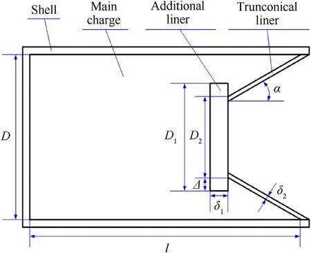
Fig.1. Trunconical hypercumulation shaped charge.
Generally, formation of jet by hypercumulation shaped charge structure could be divided into three stages, as shown in Fig. 2. In the first stage,the additional liner gets the velocity of vfunder the driven of shock wave. Under ideal conditions, the shock wave propagates to the additional liner first.Restricted by its length,the additional liner cannot move freely,and the resistance coefficient is set as f(Δ). The velocity vfof additional liner along X axis can be obtained from Gurney plate collapse theory[19]
In the second stage, under the combined action of additional liner and shock wave, part of the liner collides with the additional liner and the axis of symmetry successively to form the initial hypercumulation jet and starts to flow along the inner wall of the trunconical liner, while the impact angle is π/2+β and is greater than 90°,as shown in Fig.2(a).Subsequently,a jet with large mass is formed,which would flow along the inner wall of the additional liner until the jet moves near the central axis and then has a secondary collision,and the collision angle is β1also greater than 90°,forming a high-velocity and high-mass jet head.This stage could be described by stable theory, and the velocity of jet and slug can be calculated by Ref. [20]

Fig. 2. Formation process of the hypercumulation jet.
Hypercumulation jet mass mjand slug mass msis
where f(λ)is the velocity loss coefficient of the jet moving along the additional liner,
v0is the crushing velocity of the liner element,m2is the mass of the liner forming the hypercumulation jet part.
Finally,when the liner is crushed to a certain extent,the rest of the liner would not be affected by the additional liner, and is directly pressed to form the main jet and slug part. This process could be described by PER theory[21].The velocities of this part of jet and slug could be expressed as
where ueis the velocity of shock wave sweeping over the liner.
Mass of jet and slug can be obtained according to momentum and mass conservation theorem. It is assumed that the microelement mass of the liner, jet and slug is dm, dmjand dms, then
Since the number of unknown variables in PER theory is more than that of independent equations,a formula must be introduced to close the equations. Crushing speed v0calculation model is shown in Fig. 3. The trunconical liner is divided into several micro elements and is affected by explosives in both radial and axial directions. Then the crushing speed could be expressed as

Fig. 3. Calculation model of liner collapse velocity. vp and vc could be obtained from Gurney plate collapse formula and Chanteret string collapse theory [22].
where φ is the included angle between the normal of the tangent line at the micro element of the liner and the axis of symmetry.vpis the crushing velocity component of micro element for axial charge;vcis the crushing velocity component produced by micro element on radial charge.
where Reis the outer radius of the charge corresponding to the micro element of the liner. Riis the inner radius of the charge corresponding to the micro element of the liner.Rxis the radius of the rigid surface of the charge corresponding to the micro element of the liner. mi, mtand ccare the micro element mass of the trunconical liner,the case micro element mass and the radial micro element mass of the charge,respectively. Then Rxcan be obtained by solving the following equation
3. Effect of main control parameters on the formation behavior of jet
3.1. Analysis of main control parameters
According to theoretical analysis, each component of the trunconical hypercumulation shaped charge has varying degrees of effect on the formation behavior of jet.Analyzed from the aspects of charge,additional liner,trunconical liner and shell,the main factors affecting the formation of hypercumulation jet include.
(1) Charge: diameter(D), length (l), density (ρ);
(2) Additional liner: thickness (δ1), edge protruding length (Δ),density (ρ1);
(3) Trunconical liner: cone angle (2α), thickness (δ2), truncated diameter (D2), material density (ρ2);
(4) Shell: thickness (δ3), density (ρ3).
In addition, standoff H (distance between the bottom of the truncated liner and target plate) has significant effect on jet formation, and there exists an optimal standoff. Therefore, the standoff H is also used taken as a main factor. Therefore, the jet velocity vjcan be expressed by the following relationship
According to the π theorem dimensional analysis, selecting ρ2,δ2as the basic quantity,and the dimensionless treatment of Eq.(13)is obtained
Without changing the materials of explosives, additional liner,trunconical liner and shell, the parameters about material properties meet similar conditions, and Eq. (13) can be simplified to
When keeping the length,diameter of the charge and truncated diameter of the liner unchanged,while the shaped charge structure works at constant standoff, Eq. (14) could be further simplified to
Based on the above analysis, three main dimensionless quantities related to the structural properties and jet characteristics of hypercumulation shaped charge can be obtained. Through experiment or simulation, the influence of each dimensionless quantity on the formation of hypercumulation jet can be obtained.
3.2. Formation process of hypercumulation jet
In order to analyze the formation process of hypercumulation jet, a 2D-Eulerian axisymmetric model is established based on Autodyn-2D platform, as shown in Fig. 4. The explosive, shell,additional liner and liner are meshed by Euler algorithm to reduce large deformation. The boundary condition of air (Euler) domain was set as“flow-out”to eliminate the interfere of boundary effect.The diameter and length of charge are 80 mm and 120 mm,respectively.The thickness of shell is 2 mm.The thickness and cone angle of liner are 1 mm and 50°, respectively. Top height is 1/3 of the total height of liner. The thickness of additional liner is 3 mm,and the edge protrudes 1.5 mm from the outer edge of the liner.After grid convergence verification, dimension of the grid is set to be 0.25 × 0.25 mm2, to achieve sufficient accuracy and efficiency.
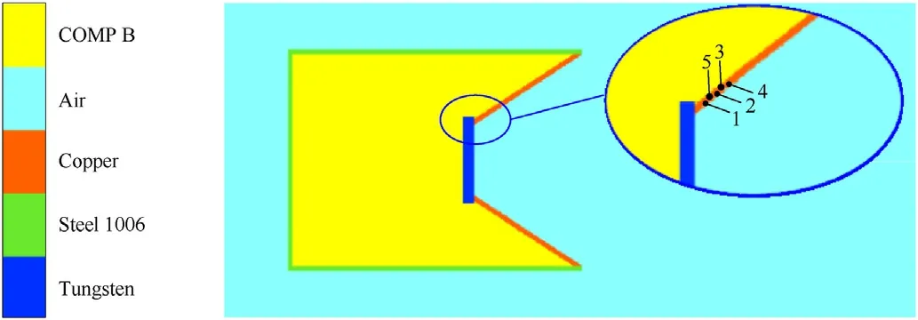
Fig. 4. Charge structure and calculation model.

Fig. 5. Formation process and pressure distribution of hypercumulation jet: (a)t = 10 μs; (b) t = 18 μs; (c) t = 20 μs; (d) t = 26 μs; (e) t = 36 μs; (f) t = 44 μs.
Materials of the main charge, shell, additional liner and truncated liner are 8701 explosive, steel 1006, tungsten and copper respectively. In the calculation, shock equation of state is used to describe the deformation behavior of metal materials, and JWL equation of state is used for the explosive. Detailed parameters of the materials are listed in Table 1 and Table 2 [23].

Table 1 Material parameters of charge structure [19].

Table 2 Material Parameters of explosive of 8701 [19].
Typical formation process and pressure distribution of trunconical hypercumulation jet is shown in Fig. 5. After the main charge is detonated, the detonation wave first reaches the upper surface of the additional liner and pushes it to move, as shown in Fig.5(a).Under the continuous action of detonation wave,the liner begins to collapse,collides with additional liner and flows along the contact surface of additional liner, as shown in Fig. 5(b). When it flows to the central axis of the charge structure, a secondary collision and successive collapse promotes to form a hypercumulation jet, as shown in Fig. 5(c). Benefiting from additional liner, the jet mass and velocity are significantly enhanced, while slug gets small initial mass and large reverse velocity. With the continuous accumulation of the jet and increase of the velocity gradient,the additional liner would stop colliding with the jet and has little effect on the subsequent jet formation. Similar to traditional jet formation process,the hypercumulation jet would stretch to form a higher velocity slender jet,as shown in Fig.5(d)-Fig.5(f).

Fig. 6. Micro element velocity time curve of liner.
Extracting the velocity at different positions on the liner, Fig. 6 shows the velocity history of gauges over time. Velocity of the micro element corresponding to gauge#1 increases slowly at first,then increases sharply to the maximum, and then tends to be flat,indicating this element directly flows into the main body of the jet.Velocity at gauge#2 experiences an increase,then decrease,before increase again trend,indicating the corresponding micro element is the first part to form the slug body, which locates in the junction area between the jet and slug. Element at gauge #3 is blocked by the subsequent elements when it flows into the jet,thus its velocity drops gradually after a short increase and forms the slug. Element at gauge#4 directly joins the slug. Combining the curves,collapse velocity of the liner could be obtained. It is worth noting that the velocity at gauge #5 reaches the negative range, indicating that some slug bodies extend backward and have secondary collision with the additional liner.
3.3. Effect of main control parameters on jet formation
By focusing on the structure of additional liner and truncated liner,theoretical analysis and numerical modelling are employed to study the effects of main control parameters,i.e.δ1/δ2,Δ/δ2and α,on the formation and characteristics of jet.
The effects of δ1/δ2, Δ/δ2, α on jet length and velocity distribution are depicted in Fig. 7. Low-velocity, medium-velocity and high-velocity areas are divided when the velocity is below 3 km/s,between 3-6 km/s and above 6 km/s. As shown in Fig. 7(a), with the increase of dimensionless quantity δ1/δ2, velocity of the low and medium velocity area gradually decreases, while the jet tip velocity increases and the jet length first increase and then decrease. By comparison, though the dimensionless quantity Δ/δ2has little effect on the overall distribution of velocity and length,the tip velocity occurs minor increase as Δ/δ2increase, as shown in Fig.7(b).However,with the increase of cone angle α,velocity of in each area of the jet gradually decreases. Length of the jet in high and medium velocity area gradually shortens, and shows opposite trend in low velocity area. In addition, velocity at jet head section fluctuates greatly with the increase of cone angle, indicating that there are more fracture gaps at the front end of the jet.
Fig. 8 shows the effect of dimensionless quantity δ1/ δ2, Δ/δ2and α on jet tip velocity at 1.5D standoff,from the point of view of both numerical modelling and theoretical modelling. While numerical results fluctuate near the theoretical, the jet tip velocity increases with the increase of dimensionless quantity δ1/ δ2, decreases with the increase of Δ/δ2and first increases and then decreases with the increase of dimensionless quantity α.
4. Orthogonal optimization of hypercumulation shaped charge
4.1. Orthogonal optimization method
The above analysis concludes the effect of single dimensionless quantities on hypercumulation jet and its formation. However,under the joint effect of multiple factors, distinguishment of the significance of each factor brings challenge.Further analysis on the significance of each factor would provide important guide for design and application of trunconical hypercumulation shaped charge structure.
Through orthogonal optimization method [24], effect and significance of the five factors on the indicators of jet tip velocity vjand effective jet length L of hypercumulation jet could be obtained, as shown by different colors in Fig. 9. Taking 3 km/s as the critical penetration velocity,effective jet length denotes the part from the section of 3 km/s to jet tip.The cone angle α(A),truniconical liner wall thickness δ2(B), additional liner thickness δ1(C), additional liner edge protruding length Δ(D)and standoff H(E)were selected as orthogonal optimization parameters,and four levels were set for each factor, as listed in Table 3. The simulation analysis scheme is designed by L16(45)orthogonal table,a total of 16 groups,as shown in Table 3.

Table 3 Factors and levels of orthogonal experiments.

Fig. 7. Effect of δ1/δ2, Δ/δ2, α on jet length and velocity distribution: (a) δ1/δ2; (b)Δ/δ2; (c) α.
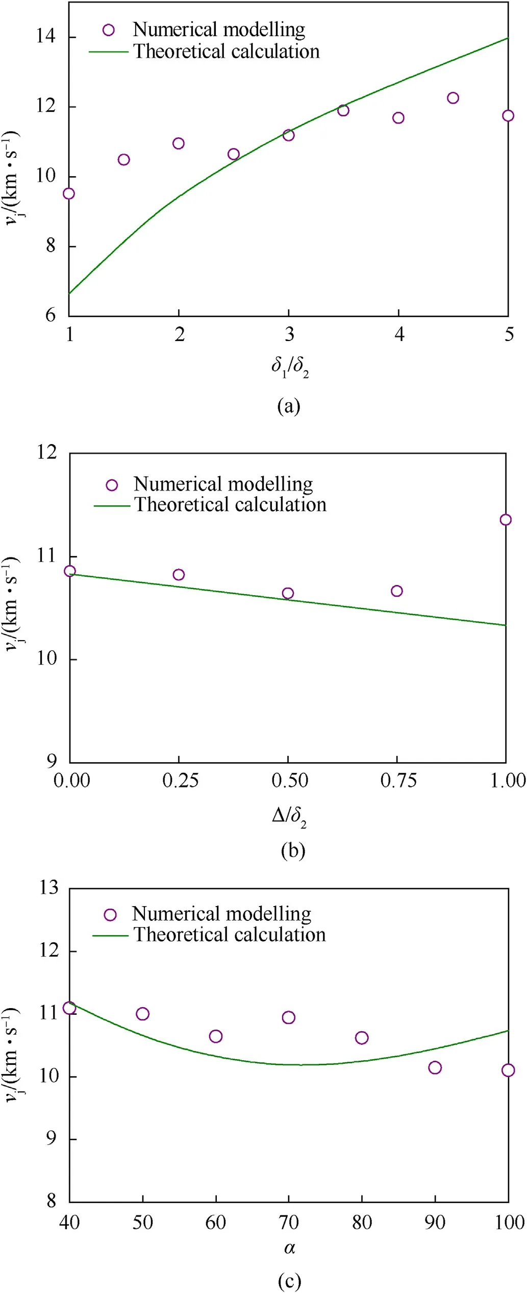
Fig.8. Effect of dimensionless quantity δ1/δ2,Δ/δ2 and α on jet tip velocity:n:(a)δ1/δ2; (b) Δ/δ2; (c) α.

Fig. 9. Tip velocity vj and effective jet length L.
4.2. Orthogonal optimization results and analysis
The 16 groups of orthogonal experimental scheme listed in Table 3 were numerically simulated, and the jet tip velocity vjand effective jet length L were listed in Table 4.
According to the numerical results,the jet tip velocity of scheme 9 is 11959.0 m/s,corresponding to the factor combination of A3-B2-C3-D4-E2. The longest effective jet length is 15.9 cm, and the corresponding test combination is A1-B4-C4-D4-E4.
The influence of the factors over the indicator were determined using range(R)analysis,as shown in Table 5 and Fig.10[25].Based on the range analysis,order of the significance of each factor could be obtained. The order of the influence of each factor on jet tip velocity is C>B>E>A>D,i.e.δ1>δ2>H>α>Δ.Similarly,the order of the influence of each factor on jet length is D>E>A>C>B,i.e.
Δ>H>α>δ1>δ2.
Because the level change of the main factors has great impact on the indicators of jet, the optimal level must be selected, and the other secondary factors shall be selected according to the actual situation.Accordingly,four optimized factor level combinations are selected for jet tip velocity and effective jet length, which are A1-B1-C4-D4-E1,A3-B1-C4-D4-E1,A1-B1-C2-D3-E4 and A1-B3-C2-D3-E4.The numerical simulation is carried out respectively,and the calculation results are listed in Table 6.
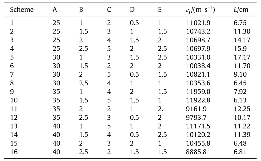
Table 4 Orthogonal experimental scheme and results.

Table 5 Range analysis of each factor.
Comprehensively considering the tip velocity and effectivelength of the jet, jet tip velocity in combination 1 and 2 is higher,but the effective jet length is much lower and the jet is not fully stretched,which would greatly affect the penetration performance of the jet.By comparison,combination 3 and combination 4 present advantage in jet tip velocity and effective jet length,so the optimal level should be selected from combination 3 and combination 4.
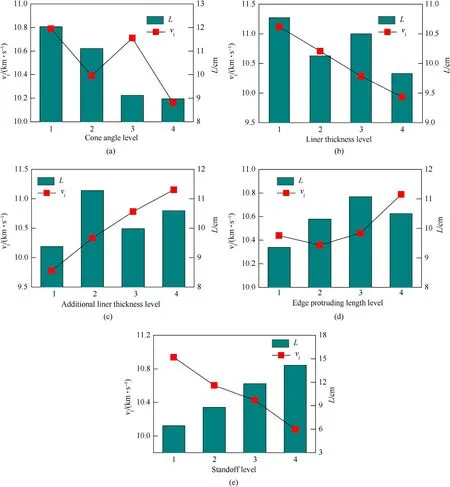
Fig.10. Effect of factors on jet tip velocity and jet length: (a) α; (b) δ2; (c) δ1; (d) Δ; (e) H.
5. Experimental verification
Based on the orthogonal optimization results, penetration experiments were conducted to verify the optimal factor combination from combination #3 and combination #4, as well as the advancement over traditional conical liner shaped charge. The specific experimental conditions are listed in the Table 7.

Table 7 Experiment conditions.

Table 8 Experimental results.
The conical liner, additional liner and trunconical liner used in the experiments are shown in Fig. 11. With specially designed mould, main charge of composition B explosive is shaped and the liners are amounted, as shown in Fig.12. The experimental setup consists of detonator, shaped charge structure, protective plate,standoff and target,as shown in Fig.13.The laminated steel target consists of six steel ingot with the dimension of Φ150 mm×120 mm and is placed on the platform.The standoff cylinder is arranged on the center of the top steel target.Upon the standoff cylinder, a steel protective plate with central hole is horizontally placed and the shaped charge structure is placed on it. Finally,the shaped charge structure would be ignited by the detonator amounted on the top.

Fig.11. Liners used in the experiments.

Fig.12. Shaped charge structure.
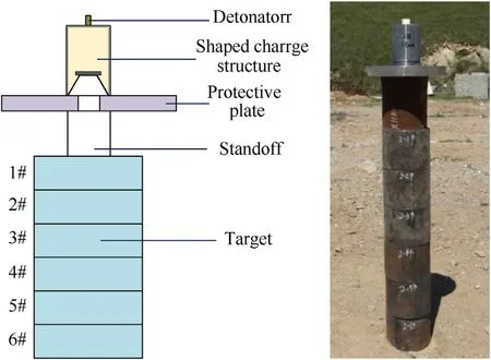
Fig.13. Experimental setup.
Fig. 14 presents the high-speed video sequences of the penetration experiments. Experimental results of the three shaped charge structures are shown in Fig. 15. Observing the damage of each steel ingot and the overall perforation,it can be seen that there are obvious black residues near the penetration hole of the first layer of target plate under various experimental conditions, with petal shaped uplift around and large opening diameter.Meanwhile,a large number of pits with different depths on the surrounding surface,which is due to the fragmentation of the liner that failed to form the jet under the action of charge detonation to form natural fragments, which, together with the fragmented additional liner,caused certain damage to the surface of the target plate.Due to the boundary effect,there are jet and target residue between the lower target plates.The diameter of the penetration hole of the first target is much larger than that of the subsequent ones,and the diameter shows a decreasing trend.

Fig.14. High-speed video sequences of the experiments.
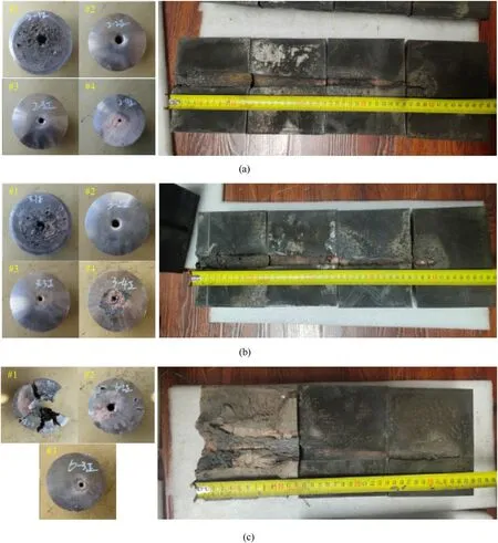
Fig.15. Damage effects of the steel targets: (a) Combination 3; (b) Combination 4; (c) Conical liner shaped charge.
Due to that the penetration holes are elliptical,sizes of the holes are described by a major axis and minor axis. Specific penetration depths of the three shaped charge structure and penetration hole sizes are listed in Table 8.The penetration depth of combination 3#and combination 4# are 400 mm and 395 mm respectively, much higher than that of the conical liner shaped charge, and proving that among the combinations obtained by orthogonal optimization,the optimal combination is combination 4#. By comparison,penetration depths from combination 3 and combination 4 are 15.50% and 16.96% higher over the conical liner shaped charge.Meanwhile, though penetration hole sizes are difficult to compare quantitatively, lengths of major and minor axis present that the holes are obviously larger from optimized combinations. Meanwhile, to verify the repeatability of the experiments, three numerical simulations correspond to the experimental condition are conducted,and penetration depth of combination 3#,combination 4# and conical liner shaped charge are 405 mm, 412 mm and 368 mm,respectively.Numerically obtained penetration depths are higher than that from the experiments due to a more ideal charge structure and condition.However,the results also demonstrate the same comparison relationship as the results and the combination 4# is the optimal combination in this research. That is, under the standoff of 2.5CD,the optimal trunconical hypercumulation shaped charge structure in this research consists of a copper liner of cone angle of 50°and wall thickness of 2 mm, an additional liner of thickness of 3 mm and edge protruding length of 1.5 mm, and would achieve a penetration depth of 400 mm on steel target.
6. Conclusions
Combining the methods of theoretical, numerical and experimental, this research focuses on the jet formation behavior and optimization of trunconical hypercumulation shaped charge structure.The main conclusions are as follows:
(1) Based on the three-stages division,micro element method as well as comprehensive consideration of the effect additional liner, truncated liner, main charge and shell, formation theory of trunconical hypercumulation shaped charge jet is established.
(2) Dimensional analysis of the main control parameters affecting the formation behavior of hypercumulation jet is carried out. The effect of dimensionless quantities of δ1/δ2,Δ/δ2and α on jet tip velocity and jet length are obtained.
(3) Orthogonal optimization of the trunconical hypercumulation shaped charge structure is carried out by numerical modelling. The results show that order of the significance of each factor on jet tip velocity is δ1>δ2>H>α>Δ. The order of the influence of each factor on jet length is Δ>H>α>δ1>δ2.
(4) Penetration experiments of trunconical hypercumulation shaped charge based on the orthogonal optimization reveals its advantage over traditional conical shaped charge structure. By comparison, penetration depths from combination 3# and combination 4# are 15.50% and 16.96% higher over the conical liner shaped charge,while the penetration holes are also larger from optimized combinations. Finally, the optimal trunconical hypercumulation shaped charge structure in this research consists of a copper liner of cone angle of 50°and wall thickness of 2 mm, an additional liner of thickness of 3 mm and edge protruding length of 1.5 mm,and would achieve a penetration depth of 400 mm on steel target.
Declaration of competing interest
The authors declare that they have no known competing financial interests or personal relationships that could have appeared to influence the work reported in this paper.
Acknowledgements
The authors would like to acknowledge the support from the Beijing Municipal Natural Science Foundation(Grant No.1214022).
- Defence Technology的其它文章
- Camouflaged people detection based on a semi-supervised search identification network
- A novel modification method for the dynamic mechanical test using thermomechanical analyzer for composite multi-layered energetic materials
- An improved SLAM based on RK-VIF: Vision and inertial information fusion via Runge-Kutta method
- Shock response of cyclotetramethylene tetranitramine (HMX) single crystal at elevated temperatures
- A super resolution target separation and reconstruction approach for single channel sar against deceptive jamming
- Angular disturbance prediction for countermeasure launcher in active protection system of moving armored vehicle based on an ensemble learning method

