A nonlinear creep model for surrounding rocks of tunnels based on kinetic energy theorem
Wenbo Liu ,Hui Zhou,* ,Shugung Zhng ,Shui Jing ,Liu Yng
a State Key Laboratory of Geomechanics and Geotechnical Engineering,Institute of Rock and Soil Mechanics,Chinese Academy of Sciences,Wuhan,430071,China
b University of Chinese Academy of Sciences,Beijing,100049,China
c Guangxi Key Laboratory of Geomechanics and Geotechnical Engineering,Guilin University of Technology,Guilin,541004,China
d School of Civil Engineering Guilin,University of Technology,Guilin,541004,China
Keywords:Internal energy Kinetic energy theorem Perzyna viscoplastic theory Nishihara model Accelerated creep Initiating threshold
ABSTRACT The initiating condition for the accelerated creep of rocks has caused difficulty in analyzing the whole creep process.Moreover,the existing Nishihara model has evident shortcomings in describing the accelerated creep characteristics of the viscoplastic stage from the perspective of internal energy to analyze the mechanism of rock creep failure and determine the threshold of accelerated creep initiation.Based on the kinetic energy theorem,Perzyna viscoplastic theory,and the Nishihara model,a unified creep constitutive model that can describe the whole process of decaying creep,stable creep,and accelerated creep is established.Results reveal that the energy consumption and creep damage in the process of creep loading mainly come from the internal energy changes of geotechnical materials.The established creep model can not only describe the viscoelastic-plastic creep characteristics of rock,but also reflect the relationship between rock energy and creep deformation change.In addition,the research results provide a new method for determining the critical point of creep deformation and a new idea for studying the creep model and creep mechanical properties.
1.Introduction
During construction of deep tunnels,the rheological deformation of surrounding rocks has an unfavorable impact on tunnel’s deformation and failure characteristics (Yang and Li,2018).The deep surrounding rock is disturbed by many factors,e.g.high temperature,high stress and strong disturbance,which will change its mechanical properties (Hendron and Patton,1987).In addition,micro-defects are commonly observed inside the rock mass.These initial micro-defects will not only affect the final failure form of the rock mass,but also change the mechanical properties of the deep surrounding rock significantly(Heap et al.,2019;Yang et al.,2013;Zhou et al.,2021a).According to the first law of thermodynamics,the deformation and failure of rock under loading are the phenomena of instability.It also belongs to the process of energy accumulation and dissipation conversion in the rock (Wu et al.,2017).Therefore,the deformation and failure process of all materials in nature can be explained by the law of conservation of energy.In deep rock excavation,the entire deformation process of the surrounding rock is accompanied by energy input,accumulation,release,and dissipation(Sun et al.,2016;Cheng et al.,2021a).These four energy forms continuously transform into one another during the deformation of the surrounding rock,and the transfer and transformation of energy completely satisfy the law of conservation of energy.In recent years,more and more scholars use the law of conservation of energy and energy dissipation theory to explain the deformation and instability mechanism of rock(Eslami et al.,2019).
The most mature and widely used rock creep model is the component combination model.The series-parallel rule is adopted to combine elastic elements,viscous elements and plastic elements.This model can better reflect the creep characteristics of rock.However,studies on this approach found that the classical component combination models (i.e.Bingham,Burgers and Nishihara model)can only describe the steady-state creep of rock under a low-stress state.As such,it cannot describe the unsteady creep of rock under a high-stress state.In particular,the model cannot explain the accelerated creep stage,where the nonlinear characteristics are particularly pronounced.Therefore,constructing a creep model is the challenge and focus of studies on rock creep.The most important aspect of these studies is how the model can describe the accelerated creep effectively (Uwe et al.,2013).After decades of theoretical research development,scholars have achieved fruitful results in creep model research.For instance,Griggs(1939) conducted laboratory rheological tests on rocks with different lithologies.He discovered the range of the ultimate failure load required for the occurrence of creep phenomenon in rocks.A custom logarithmic function was used for the first time to fit the creep curve.Based on the linear homogenization method and irreversible thermodynamics theory,Wang et al.(2015) believed that the evolution of cracks under loading has a certain influence on rock damage.Therefore,a damage model was established considering the evolution law of critical cracks,and then a damagefriction coupled creep model was established.Ultimately,the obtained numerical data could better predict the experimental data.Hou et al.(2018)constructed a model considering that the rock has initial damage.The model can describe the whole process of creep well,and reflect the effect of initial damage on rock deformation.Liu et al.(2019)used variable order fractional derivative to smooth the dashpot.Combined with the experimental data,the function between viscosity coefficient and time was constructed,and then a new creep model was established.Considering the von Mises equivalent plastic mechanics theory,Zhou et al.(2021b)connected existing elements in series and in parallel to obtain a four-element model.This model was substituted into the viscoplastic deformation equation of the circular tunnel.By combining with the Hoek-Brown criterion,the viscoplastic solution was obtained.It is found that the obtained results are basically consistent with the actual deformation data.Considering data from accelerated creep test and the influences of shape parameters,scale parameters,peak stress,peak strain,and confining pressure on damage,Cheng et al.(2021b) developed a novel creep model.This model outperforms the conventional model in describing the characteristics of accelerated creep and predicting the deformation law of surrounding rock.Liu et al.(2021) considered that the creep parameters would degrade under long-term loading.Compared the experimental data with the calculated curve by the model,a function between creep parameters and time was obtained.Substituting this function into the original model,an improved unsteady creep model was obtained.The above research results demonstrated the creep characteristics of deep surrounding rock under different external influences.By combining the characteristics of creep deformation and accelerated creep deformation of rocks,various macroscopic creep models and micro-particle flow models were established.Although a substantial amount of researches have been conducted on the energy evolution law of rocks (Xie et al.,2005,2009;Gong et al.,2021),few studies have focused on the use of the kinetic energy principle to reveal the mechanism of rock creep failure(Zhang et al.,2019a).
In this study,the law of energy evolution at three deformation stages of rock creep is analyzed by combining the law of conservation of energy.The decaying creep stage is primarily dominated by elastic deformation.During the decaying creep deformation stage,energy is mainly stored in the form of elastic energy.From a microscopic perspective,rocks are composed of countless microscopic particles combined through chemical bonds,which bind to each other through attractive forces.The stable creep stage is primarily dominated by plastic deformation.Energy accumulation and dissipation also occur during stable creep deformation.When the elastic potential energy inside the rock reaches a certain value,the chemical bonds between the microscopic particles break.The energy transformed by the external force on the rock can be divided into two parts,i.e.elastic energy and dissipative energy.When the creep deformation enters the accelerated creep stage,the deformation rate of the rock increases rapidly,and the rock will deform in a short time.When the plastic deformation inside the rock exceeds the limit value,macro-cracks can be observed in rock,which expand rapidly.At the accelerated creep stage,the work done by the external force is mainly converted into the kinetic energy.
Subsequently,the triaxial creep test of the rock is carried out using the MTS815.04 test system.Based on the kinetic energy principle,a constitutive model considering accelerated creep is constructed.It can provide a theoretical basis for solving practical engineering problems encountered in the tunnel support and the prevention of surrounding rock instability.
2.Kinetic creep model of rock
2.1.One-dimensional (1D) creep model
The classic creep deformation curve of rock is shown in Fig.1(Lyu et al.,2021).During the creep process of triaxial loading,an energy conversion system forms between the inside and outside of the rock.Rock creep deformation failure is primarily caused by the development and expansion of void defects in the rock.Essentially,such deformation is the process of energy accumulation and dissipation between the rock and the external system.In addition,many researches have proven that the energy principle is effective in revealing the mechanism of rock deformation and failure and solving the problem of rock creep deformation.Therefore,establishing an accelerated creep model based on energy theory can better describe the whole process of rock creep deformation.This model can provide theoretical guidance for studying the long-term deformation of the surrounding rock in the actual engineering tunnel.
The Perzyna viscoplastic model can better describe the nonlinear characteristics of rocks at the viscoplastic deformation stage (Zhou et al.,2011).The model can be expressed as

where η is the viscosity coefficient,φ(F) is an arbitrary function of the yield function,{m}is the direction of the viscoplastic flow,andis viscoplastic strain rate.When the correlation flow law is adopted,the flow direction of{m}is consistent with the plastic flow direction.The value of {m} equals 1.
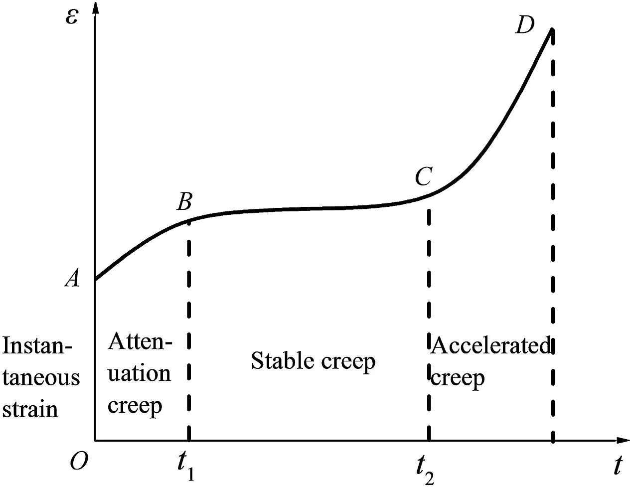
Fig.1.Classic creep deformation curve of rock.
The arbitrary function φ(F) of the yield function can be expressed as

wherenis a constant,and σsis the yield strength.
In the process of creep deformation,the creep characteristics of rocks are affected not only by the applied stress but also by external factors,such as temperature,time,and seepage pressure.These influencing factors are all state variables that can describe the internal properties of the material.Thus,the creep characteristics of rock can be analyzed from the perspective of rock internal properties.Variations in the mechanical behavior of rock will inevitably change its internal energy (Zhu et al.,2013).Essentially,the creep failure is caused by energy conversion and dissipation inside the rock.Therefore,the energy principle can be used to solve the problem of creep deformation (Shinata et al.,2007;Zhang et al.,2013).Given the difference between the deformation mechanism of instantaneous elastoplastic strain and the creep deformation mechanism,only the creep deformation at the viscoplastic stage is considered here.The energy principle is used to improve the arbitrary function of the yield function,and Eq.(2)is improved:

whereFis the yield function,σ is the stress of rock,ε is the strain of rock,andis the critical strain energy density.
When stress acts on the rock specimen,the work done by the external force on the rock per unit of time can be expressed as

where ΔWis the work done by the external force on the rock in unit time,and Δε is the strain of the rock per unit time.
According to the kinetic energy theorem,the work done by the resultant external force on an object is equal to the amount of change in the kinetic energy of the object.The change in the kinetic energy of the rock element during creep deformation per unit time can be expressed as

where ΔEkis the change in the kinetic energy of the rock element during creep deformation per unit time,Mis the rock mass,and Δvis the strain rate of rock.
As the work done by the external force on the rock cannot be completely converted into the kinetic energy of the rock,a kinetic energy correction coefficient are introduced,resulting in

where λ is the correction coefficient.
According to the momentum theorem,the change in momentum of a rock per unit time during the loading process is equal to the impulse of the applied external force,which is expressed as

At the stable creep stage,the creep strain rate of the rock is constant,while at the accelerated creep stage,the creep strain rate of the rock is changing.Thus,the time Δtin Eq.(7) should be a polynomial function with respect to time,resulting in

wheref(t)is a polynomial function with respect to time,which can be expressed as

whereaiis a constant.
Substituting Eq.(8)into Eq.(6),the relationship between creep strain and time can be obtained as

Substituting Eq.(10) into Eq.(3),an arbitrary function of the yield function improved by the energy principle can be obtained as

The value of the critical strain energy densityat the intersection between the decaying creep and stable creep stages can be expressed as

Substituting Eq.(12)into Eq.(11),the expression of the arbitrary function of the yield function can be obtained as

where λ1is the correction coefficient of the kinetic energy at the stable creep stage,andn1is the constant of any function of the yield criterion at the stable creep stage.
Substituting Eq.(13) into Eq.(1),a creep rate model that describes the law of the stable creep change can be obtained as

At the stable creep deformation stage,the creep rate of the rock can be considered to be constant.Therefore,Eq.(14) can be expressed as

where η2is the viscosity coefficient at the stable creep stage.
Integrating Eq.(15),a creep model describing the law of the stable creep change can be obtained as

where Γ is the critical strain energy density at the intersection between decaying creep and stable creep stages,andis critical strain energy density at the intersection between the stable creep and the accelerated creep.
At the accelerated creep stage,the creep rate of the rock is a variable.Therefore,Eq.(14) is transformed into a creep rate model that can describe the changing law of the accelerated creep as

The critical strain energy density valueat the intersection between the stable creep and the accelerated creep stages can be expressed as

whereAis the end-face area of rock sample,andLis height of rock sample.
Integrating Eq.(17),we can obtain a creep model that can describe the law of the accelerated creep change as

where η3is the viscosity coefficient at the accelerated creep stage.
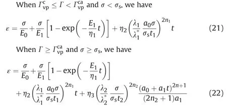
The instantaneous strain and decaying creep strain of the creep are described by the Kelvin model (De,1999).Combining Eqs.(16)and (19),the creep constitutive model based on the principle of kinetic energy can be obtained as follows.

whereE0is the elastic modulus of the elastomer,E1is the elastic modulus of the viscoelastic body,and η1is the viscosity coefficient of the viscoelastic body.
2.2.Three-dimensional (3D) creep model
In general,the surrounding rock of the Sichuan-Tibet railway tunnel is in a complex three-way stress state.The 1D creep model constructed above cannot describe the creep deformation of the surrounding rock in practice.Therefore,the 1D creep model must be transformed into a 3D one (Rutter 1972).The 3D creep model can better reveal the actual creep deformation law of the tunnel,which is of great significance for improving the theory of rock rheology.
The elastic and viscoelastic models can be transformed by analogy.According to the generalized Hook’s law,the 3D constitutive relation of the elastic body is(Zhang et al.,2019b)shown as

whereSijandeijare the stress and strain deviators,respectively;σkkand εkkare the first invariants of the stress tensor and strain tensor,respectively;G0is the elastic body shear modulus;andKis the bulk modulus.
Therefore,the strain of the elastic body()can be expressed as

The volume change of the rock is assumed to be elastic,and the rheological properties are mainly manifested in shear deformation.The 3D constitutive relation of viscoelastic body can be obtained as

However,the yield function and the plastic potential function are involved in the transformation of the 3D viscoplastic model,and the analogy method cannot be used for transformation.In the creep process,the Drucker-Prager yield function is selected in the continuously differentiable generalized von Mises criterion.

whereJ2is the second invariant of the stress tensor.
The detailed steps of transforming the nonlinear creep model from 1D to 3D refer to a viscoelastic-plastic creep constitutive model based on strain energy theory established by Shen et al.(2014).The 3D creep model of the rock is as follows.
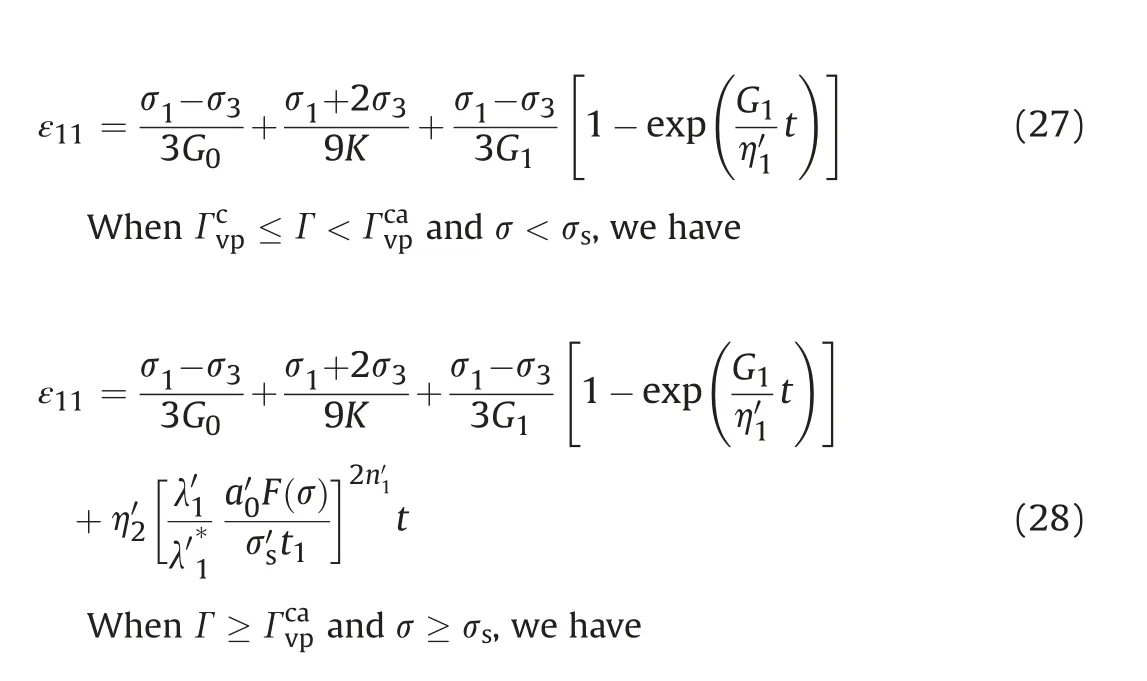

whereandare the constants in the 3D creep model and generally they are both equal to 1,is the viscosity coefficient of the viscoelastic body in the 3D model,is the viscosity coefficient at the stable creep stage in the 3D model,is the viscosity coefficient at the accelerated creep stage in the 3D model,andare the constants in the 3D model,is the correction coefficient of the kinetic energy at the stable creep stage,is the kinetic energy correction coefficient at the intersection point of the decaying creep and the stable creep stages in the 3D model,is the correction coefficient of the kinetic energy at the accelerated creep stage in the 3D model,is the kinetic energy correction coefficient at the intersection point of the stable creep and accelerated creep stages in the 3D model,andis the long-term strength in the 3D model.
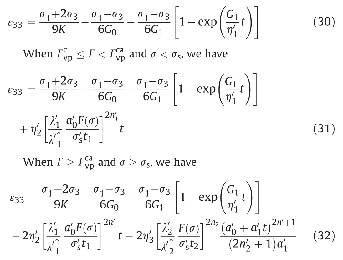
Substituting Eq.(23) into Eqs.(25) and (26),a nonlinear viscoelastic-plastic creep constitutive model of the rock based on the kinetic energy principle in a 3D model can be obtained.
Similarly,the radial creep equation of rock in the 3D model is obtained as follows.
3.Laboratory triaxial creep test
3.1.Test equipment and test process
The MTS815.04 rock triaxial test system at the State Key Laboratory of Geomechanics and Geotechnical Engineering,Institute of Rock and Soil Mechanics,Chinese Academy of Sciences,was used for the test.Rock uniaxial,triaxial,and stress path tests can be perform using this system.The maximum axial load can reach 4600 kN.The maximum confining pressure can reach 140 MPa.The frame stiffness is 11 GN/m.The MTS815.04 rock test system is shown in Fig.2a.As the surroundingrockislocatedatgreatdepth(800-1000m)inacomplex geological environment and affected by the surrounding mines and faults,the surrounding rock in this area has experienced high geostress for a long time.After simple processing,the extracted rock block was brought back to the laboratory for processing and made into a standard cylinder with the dimensions of 100 mm in height and 50 mm in diameter.The samples with evident defects in appearance were eliminated.Moreover,the diameter deviation of the remaining rock samples should be no more than 0.3 mm,the height error should be no more than 0.05 mm,and the maximum deviation of the axis should be less than 0.25º.Finally,after testing by the wave velocity tester,the rock samples with the same wave velocity were used in the test.The photos of rock samples after processing are shown in Fig.2b.
The maximum principal and minimum principal stresses are 30 MPa and 25 MPa,respectively.The confining pressures are 20 MPa and 25 MPa.In the laboratory,the confining pressures of 20 MPa and 25 MPa were selected.A single specimen was loaded separately to conduct the loading creep test.To determine the creep test scheme of rocks under different confining pressures,triaxial compression tests were carried out under the same conditions.According to the peak stress obtained in the triaxial compression test,the loading scheme of the creep test was determined.The initial stress level is 50%of the peak strength of the sandstone in the triaxial compression test.The compression test scheme with triaxial loading is described as follows:
(1) A small axial load is applied at a loading rate of 500 N/s so that the specimen and the indenter are in close contact.
(2) The confining pressure is loaded to a predetermined value at a loading rate of 500 N/s according to the hydrostatic pressure condition.
(3) The upper limit of the corresponding displacement is designed (the axial direction is controlled by displacement loading).The loading rate is 0.002 mm/s until the rock sample is damaged.
(4) When the applied stress reaches the peak stress,the confining pressure remains unchanged.The axial strain is applied at the same rate until the residual stress-strain relationship of the rock sample is measured,and the axial and confining pressures are gradually unloaded to zero.The test data are saved and exported.
(5) Data collection is terminated.The axial pressure is released,followed by the confining pressure.Then,the specimen is extracted.
(6) The test data in the data acquisition system are exported.Then,the data are saved.
The creep test scheme with triaxial loading is described as follows:
(1) The stress levels of specimens with a confining pressure of 20 MPa are divided into five groups:55 MPa,60 MPa,65 MPa,70 MPa and 75 MPa.The stress levels of specimens with a confining pressure of 25 MPa are divided into six groups:60 MPa,65 MPa,70 MPa,75 MPa,80 MPa and 85 MPa.
(2) A small axial load is applied at a loading rate of 500 N/s so that the specimen and the indenter are in close contact.
(3) The confining pressure is loaded to a predetermined value at a loading rate of 500 N/s according to the hydrostatic pressure condition.
(4) The axial load is applied to a predetermined value at a loading rate of 0.002 mm/s.
(5) When the deformation caused by the first load is stabilized,the next load is applied.In turn,the load of each level is increased by 5 MPa until the specimen is deformed and destroyed.After the creep test is completed,the test data are recorded and saved.
(6) The basis for judging the stability of sandstone deformation is as follows.When the creep deformation of the specimen is no more than 0.001 mm within 2 h at the stable creep stage,the deformation is considered stable.
(7) Data collection is terminated.The axial pressure is first released,followed by the confining pressure.Then,the specimen is extracted.
(8) The test data in the data acquisition system are exported and saved.
3.2.Analysis of triaxial compression test results
The triaxial compression test under different confining pressures was conducted following the above steps.The stress-strain curves are shown in Fig.3.
Fig.3 demonstrates that under the same confining pressure,the variation range of the radial strain of sandstone is smaller than that of the axial strain.It also shows that the increase of confining pressure affects the development of the radial deformation of sandstone.Under low confining pressure,the sandstone deformation has a relatively clear compaction stage.However,with the increase of confining pressure,the nonlinear characteristics of pore compaction deformation gradually weaken.After entering the elastic strain stage,the radial deformation rate increases,and the curve tends to deviate from the negative semi-axis ofx.Both the axial and radial strains begin to increase sharply at the plastic strain stage beyond the yield point and before the peak point.When the peak point is reached,the sandstone undergoes volume expansion failure.However,the sandstone still has a certain bearing capacity.Meanwhile,the deformation of the sandstone enters the post-peak strain-softening stage.At this stage,the sandstone strain will continue to increase.
3.3.Analysis of creep test results
According to the test results,the loading creep curve is transformed by the data processing method proposed by Chen et al.(2006),to eliminate the influence of historical loads on the creep data (Fig.4).
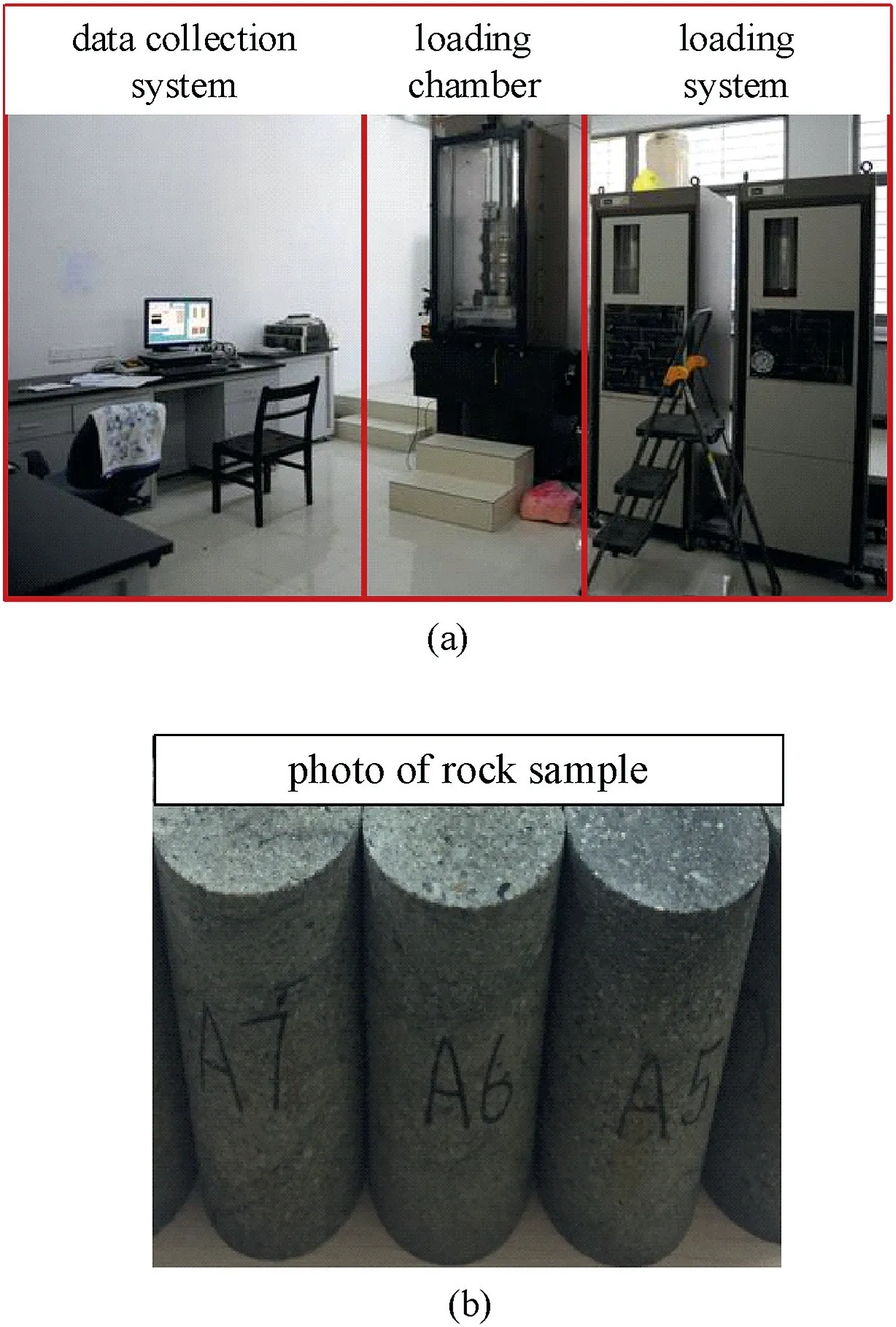
Fig.2.(a) The MTS815.04 rock test system and (b) sandstone sample.
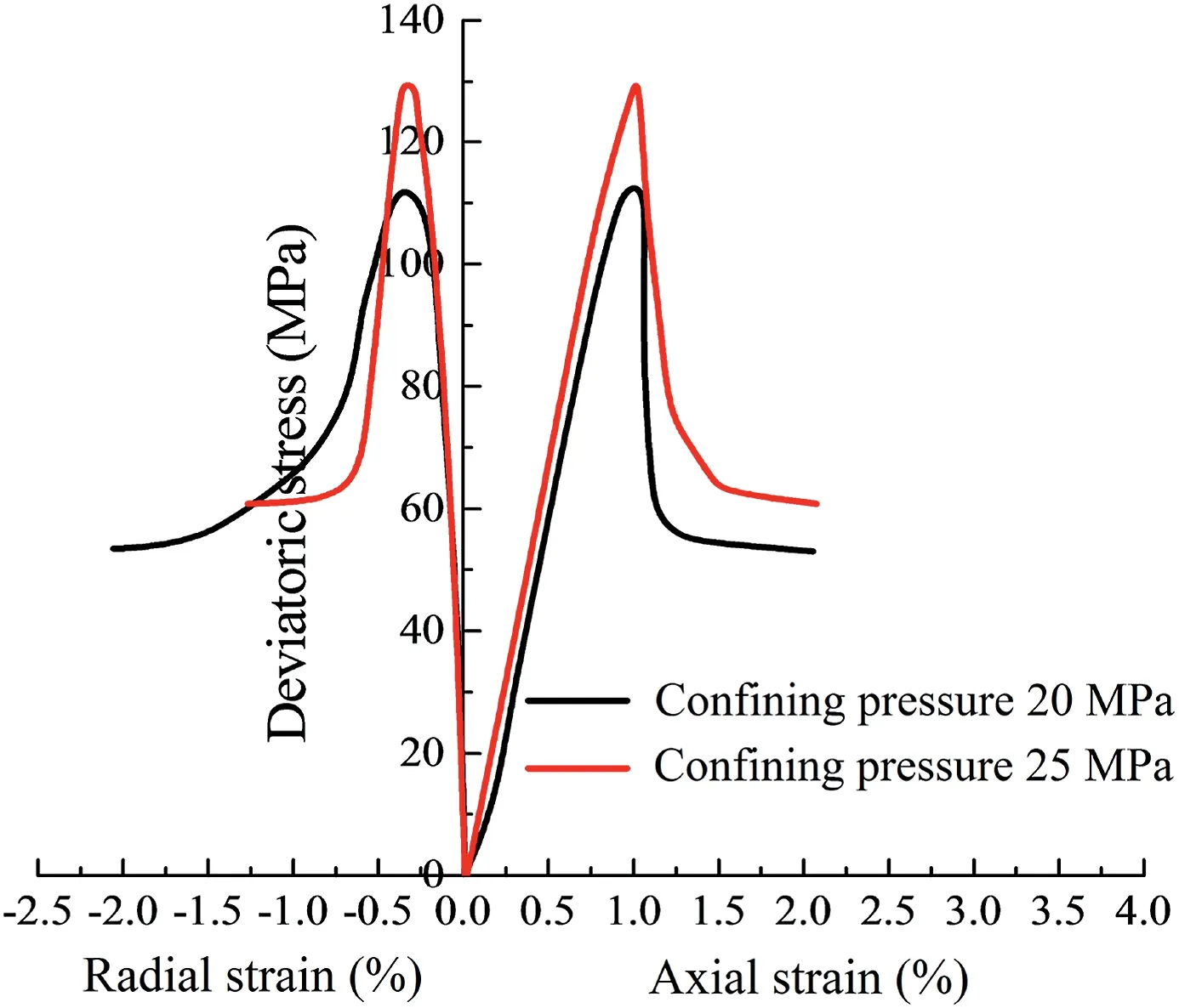
Fig.3.Stress-strain curves under different confining pressures.
After the first-level constant load=Δσ′is applied to the sample,the sample enters the stable creep stage from the decaying creep stage after a duration ofT1.The creep deformation generated at this time is.When the next-level load+Δσ′is applied,the creep deformation of the specimen with a duration ofT2increases byrelative to the creep deformationat the end of the firstlevel load.By subtracting the creep deformation increment from the creep deformation under the second-level load,the corrected second-level load creep deformationcan be obtained.By repeating the above steps,all corrected axial creep curves under different confining pressures can be obtained,as shown in Fig.5.
Fig.5 demonstrates that under the same stress level,a larger confining pressure results in a smaller instantaneous deformation of the rock.This correlation indicates that an increase in the confining pressure can improve the capacity of the rock to resist deformation.In addition,this pressure restricts the generation of the instantaneous axial strain of the rock.However,the ratio of instantaneous strain to the total strain first increases and then decreases due to the numerous pores in the rock.The rock pores are first compressed at the initiation of loading.After being completely compacted,numerous cracks are formed inside the rock.This leads to a large transient strain of rock at initiation and a small transient strain later(the deformation provided by the fracture deformation is much smaller than that provided by the pore compression).
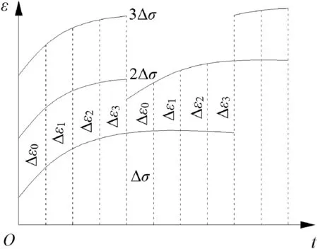
Fig.4.Data processing method.
Taking the confining pressure of 20 MPa as an example,when the stress levels are 55 MPa,60 MPa,65 MPa and 70 MPa,the sandstone creep strains are 0.00469%,0.00409%,0.00447% and 0.04723%,respectively.The ratios of the creep deformation to the total deformation are 0.0575,0.0345,0.0276 and 0.1701,respectively.The ratio of the creep deformation to the total deformation first decreases and then increases.In addition,further development of the total deformation is accounted for in the creep deformation.This indicates that the internal voids of the sandstone are constantly developing,thus leading to the more evident deterioration characteristics of the sandstone.However,the comparative analysis of transient strain and creep strain demonstrates that the ratio of the transient strain to the total strain is much larger than that of the creep strain to the total strain.This demonstrates that the damage to sandstone caused by transient strain is greater than that by creep.
Taking a confining pressure of 20 MPa as an example,when the stress level is 55 MPa,the decaying creep of the rock lasts for a long time.Then,the creep rate decays to zero.The creep time is approximately 102.14 h.When the stress level is 60 MPa,the decaying creep of the rock persists for a long time and then enters the stable creep stage.At this time,the creep time is approximately 101.23 h,and the creep deformation of the rock gradually stabilizes.When the stress level is greater than 60 MPa,the rock has a significantly accelerated creep stage.The duration for accelerated creep gradually decreases as the stress level increases.This trend indicates that the increase of stress level intensifies the development of internal damage and the expansion of cracks in the rock.This development makes the rock more prone to be damaged.
Comparing the instantaneous strains under two confining pressures,we can obtain that a greater confining pressure results in a smaller instantaneous strain under the same axial load.This reflects the restraining effect of confining pressure on the axial transient strain.Under the same axial load,a larger confining pressure results in a smaller creep strain.This correlation reflects the restraining effect of the confining pressure on the axial creep.By comparison,it can be seen that the final axial strain in the two groups of creep tests is smaller than the axial peak strain in the conventional triaxial test under the same confining pressure condition.This phenomenon should be paid attention to in practical engineering.Therefore,in the actual roadway maintenance,effective supporting measures should be taken to increase the support to the surrounding rock to ensure the long-term stability and safety of the project.These measures can also decrease the amount of deformation and deformation rate of surrounding rock.
3.4.Determination of long-term strength
According to the data in axial creep-duration test,the isochronous stress-strain curves of the rock under different stresses and time are drawn(Fig.6).Each isochronous stress-strain curve consists of a branch of gradually diverging broken lines.The development trend of each isochronous stress-strain curve gradually presents a nonlinear softening characteristic with increase of stress level.The line segments of the stress-strain relationship at different times overlap with each other at low stress level.Meanwhile,the sandstone strain exhibits a linear change.With the increase of stress level,the deformation of sandstone transforms from linear to nonlinear softening.At this point,the polyline segments begin to change from coincidence to divergence.In addition,higher stress level corresponds to greater divergence.The stress value corresponding to the divergent point is taken as the longterm strength of rock (Shen and Chen 2011).
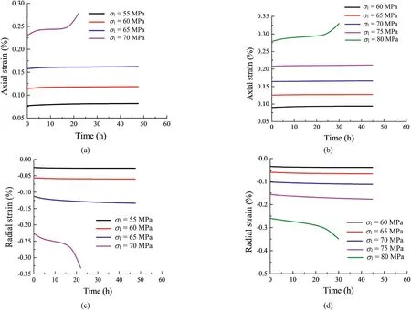
Fig.5.Creep curves of loading test on single specimen with axial strain under(a)confining pressure σ3=20 MPa and(b)σ3=25 MPa;radial strain under(c)σ3=20 MPa and(d)σ3=25 MPa σ1 is the axial stress.
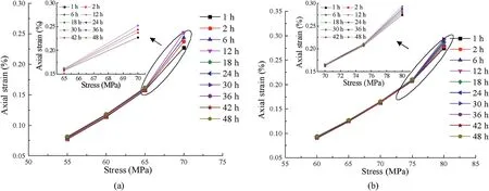
Fig.6.Isochronous relations of stress-strain: (a) σ3=20 MPa,and (b) σ3=25 MPa.
Therefore,it can be obtained that the long-term strengths of the rock are 65 MPa and 75 MPa when the confining pressures are 20 MPa and 25 MPa,respectively.
4.Model validation and parameter solving
4.1.Determination of model parameters
To simplify the calculation,the instantaneous strain generated by the rock at initiation of loading is assumed to be elastic.The rock bulk modulusKcan be determined by the spherical tensor of stress and volumetric strain:

where σmis the spherical tensor of stress,εmis the spherical tensor of strain,and εVis the volumetric strain.
The instantaneous strain of the rock can be expressed as

where ε0is the instantaneous elastic strain,and S11is the deviatoric stress tensor.
Substituting Eq.(34)into Eq.(33),the rock shear modulusG0can be obtained as

Taking the confining pressure of 20 MPa as an example,the values of creep parameters under different stresses are determined using the least square method,as shown in Table 1.

Table 1 Model parameters under different stress levels.
4.2.Verification of creep model
Substituting the parameters obtained from the inversion into the accelerated creep constitutive model,the comparisons between the calculated and test curves are shown in Fig.7.
Fig.7 demonstrates that the deduced nonlinear creep damage model conforms to the change law of the creep curve under the confining pressures of 20 MPa and 25 MPa.According to the comparison between the calculated curve and the test data,the calculated curve of the accelerated creep under low stress level is in good agreement with the test curve.At the last stage of loading,thecalculated curve and the test curve fit relatively well.However,evident deviations are observed in the local area,especially at the accelerated creep stage.Generally,an accelerated creep constitutive model can be established on the basis of the principle of kinetic energy.The model can reflect the law of creep deformation and stress state of the rock.This capacity has a guiding significance for maintaining the long-term stability of the surrounding rock in actual project.To further verify the rationality and correctness of the accelerated creep model,the conventional Nishihara model is used to fit the creep curve at the failure stage.However,from the radial creep fitting curve,we can observe that the established creep model is evidently more consistent with the experimental data at the decaying creep stage.
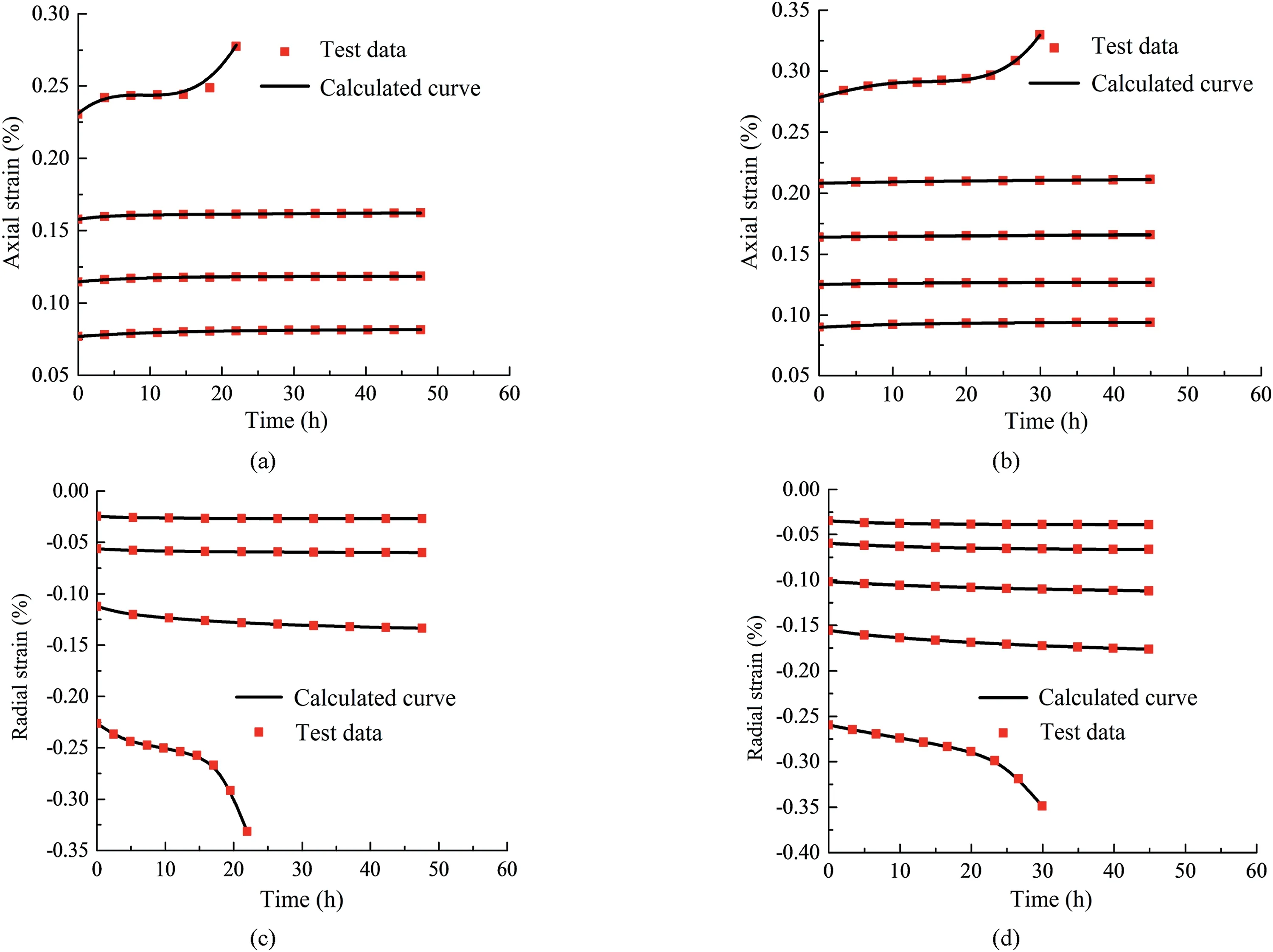
Fig.7.Comparisons of calculated and test curves with axial strain under (a) σ3=20 MPa and (b) σ3=25 MPa;and radial strain under (c) σ3=20 MPa and (d) σ3=25 MPa.
Fig.8 demonstrates that this model can describe the whole process of creep deformation well,and it can also make up for the conventional creep model’s inability to describe the characteristics of accelerated creep deformation.Therefore,constructing an accelerated creep model is correct and reasonable.
To further verify that the established model can better describe the accelerated creep deformation stage,accelerated creep test data from Liu et al.(2019) are used for verification.The comparison between the accelerated creep curve and the calculated curve under different confining pressures and stress levels is shown in Fig.9.Among them,the test curves with a confining pressure of 15 MPa and axial loads of 95 MPa and 85 MPa are compared separately(Fig.9c and d).
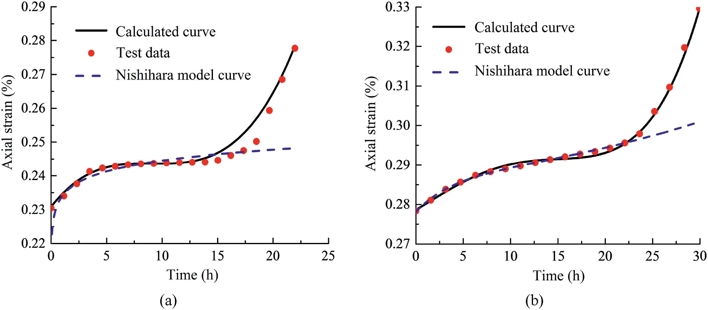
Fig.8.Comparison among the curve calculated by conventional Nishihara model,curve calculated by the proposed model,and the test curve with (a) σ3=20 MPa and (b)σ3=25 MPa.
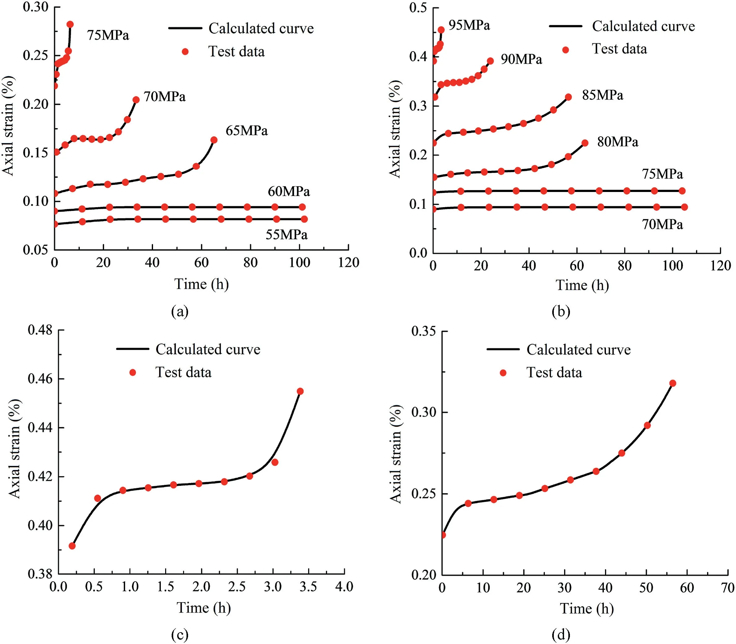
Fig.9.Comparison between test data and calculated curve with (a) σ3=10 MPa;(b) σ3=15 MPa;(c) σ1=95 MPa,σ3=15 MPa;and (d) σ1=85 MPa,σ3=15 MPa.
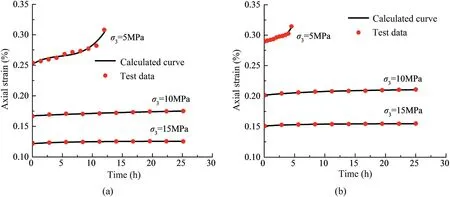
Fig.10.Comparison of unloading creep curve and calculated curve with (a) σ1=60 MPa and (b) σ1=80 MPa.
The experimental curves are in good agreement with the calculated ones in Fig.9.The calculated curve deviates from the experimental data only in the stage of accelerated creep.This fully justifies that the established model can reflect the changing law of the creep curve in the whole process.This model overcomes the conventional Nishihara model’s difficulty in describing the accelerated creep stage.Moreover,the model successfully describes the accelerated deformation in the creep phase.
The above verification only involves the loading process of rock samples.Using the unloading creep data in the literature (Liu et al.,2019) and comparing them with the calculated curve(Fig.10),the model is proved to be suitable for the unloading creep test.
As shown in Fig.10,the established creep model conforms to the change law of the creep curve under the axial loads of 60 MPa and 80 MPa (unloaded creep test).It also shows that the model is suitable and feasible for improving the conventional viscoplastic strain rate constitutive model based on kinetic energy theory,which reflects the deformation law of the whole process of rock creep.
5.Concluding remarks
The improved Nishihara model based on kinetic energy theory is a combination of nonlinear viscoplasticity theory and component method.It is easy for understanding and can effectively reflect the nonlinear creep process,which provides a new viewpoint for the study of rock creep mechanics.
From the perspective of internal energy,the kinetic energy theorem is used to define the creep mechanical behavior of materials.The duration for accelerated creep determined by this method can not only reflect the influence of the cumulative creep strain but also effectively demonstrate the influence of the stress state on the accelerated creep.With the prediction of accelerated creep,the number of required tests can be greatly reduced,which provides convenience for practical application.
This model not only describes the variation law at decaying creep and stable creep stages,but also overcomes the shortcoming of conventional Nishihara model in describing the accelerated creep stage.By applying this model to numerical simulation,the actual deformation and stress of surrounding rock can be reflected in a better way,thus its results can provide a good guide in practical engineering.
Declaration of competing interest
The authors declare that they have no known competing financial interests or personal relationships that could have appeared to influence the work reported in this paper.
Acknowledgements
This work was supported by the National Natural Science Foundation of China (Grant No.41941018),the Science and Technology Service Network Initiative of the Chinese Academy of Sciences (Grant No.KFJSTS-QYZD-174),and the Guangxi Natural Science Foundation (Grant No.2020GXNSFAA159125).
List of symbols
HViscosity coefficient
φ(F) Arbitrary function of the yield function
{m} Direction of the viscoplastic flow
NConstant
σsYield strength
FYield function
ΔWWork done by the external force on the rock in unit time
Δε Strain of the rock per unit time
Σ Stress
ΔEkChange in the kinetic energy of the rock element during creep deformation per unit time
MMass of the rock
ΔvStrain rate of the rock
Λ Correction coefficient
f(t) Polynomial with respect to time t
aiConstant related to time function,i=0~k
σsLong-term strength value
t1Time value of the initial point of the stable creep
λ1Correction coefficient of the kinetic energy at the stable creep stage
n1Constant of any function of the yield criterion at the stable creep stage
η2Viscosity coefficient of the stable creep stage
Γ Critical strain energy density value at the intersection point
λ2Correction coefficient of kinetic energy at the accelerated creep stage;t2is the initiating time of the accelerated creep
n2Constant of any function of the yield criterion at the accelerated creep stage
η3Viscosity coefficient at the accelerated creep stage
E0Elastic modulus of the elastomer
E1Elastic modulus of the viscoelastic body
η1Viscosity coefficient of the viscoelastic body
SijStress deviator
eijStrain deviator
σkkFirst invariant of the stress tensor
εkkFirst invariant of the strain tensor
J2Second invariant of the stress tensor
andConstants in the 3D model
G1Shear modulus of the viscoelastic body
KBulk modulus
G0Elastic body shear modulus
andCreep model constants in the 3D model
σmSpherical tensor of stress
εmSpherical tensor of strain
εVVolumetric strain
ε0Instantaneous elastic strain
S11Deviatoric stress tensor
 Journal of Rock Mechanics and Geotechnical Engineering2023年2期
- Journal of Rock Mechanics and Geotechnical Engineering的其它文章
- On the critical particle size of soil with clogging potential in shield tunneling
- Strength and deformation characteristics of irregular columnar jointed rock mass: A combined experimental and theoretical study
- Spatial distribution and failure mechanism of water-induced landslides in the reservoir areas of Southwest China
- Characteristics of electromagnetic vector field generated from rock fracturing
- A multi-purpose prototype test system for mechanical behavior of tunnel supporting structure: Development and application
- Geotechnical investigation of low-plasticity organic soil treated with nano-calcium carbonate
