A multi-purpose prototype test system for mechanical behavior of tunnel supporting structure: Development and application
Hongin Chen ,Xinhu You,* ,Djun Yun ,Yng Ping
a China State Construction Engineering Corporation Ltd.,Beijing,100029,China
b Tunnel and Underground Engineering Research Center of Ministry of Education,Beijing Jiaotong University,Beijing,100044,China
Keywords:Prototype test system Tunnel supporting structure Tunnel fire Lining Mechanical behavior
ABSTRACT A multi-purpose prototype test system is developed to study the mechanical behavior of tunnel supporting structure,including a modular counterforce device,a powerful loading equipment,an advanced intelligent management system and an efficient noncontact deformation measurement system.The functions of the prototype test system are adjustable size and shape of the modular counterforce structure,sufficient load reserve and accurate loading,multi-connection linkage intelligent management,and high-precision and continuously positioned noncontact deformation measurement.The modular counterforce structure is currently the largest in the world,with an outer diameter of 20.5 m,an inner diameter of 16.5 m and a height of 6 m.The case application proves that the prototype test system can reproduce the mechanical behavior of the tunnel lining during load-bearing,deformation and failure processes in detail.
1.Introduction
The physical model test has been widely applied to tunnel engineering (Gao et al.,2019;Li et al.,2019),hydraulic engineering(Zhu et al.,2010;Zhang et al.,2012),mining engineering(Ghabraie et al.,2017;Zhu et al.,2022),ocean engineering (Sun,2011;Mohammed and Fritz,2012) and other fields,and it is an indispensable method for solving engineering problems.For tunnel engineering,similar material model tests and prototype tests have been widely used in the physical test methods (Fumagalli,1973).
The similar material model test is based on the stratumstructure model,takes the similarity of mechanical parameters as the essential feature,reproduces the interaction between stratum and tunnel structure,and realises a similar description of the actual mechanical behavior (Zhang et al.,2019a;Xu et al.,2021).Nevertheless,the supporting structure is similar to a thin-walled cylinder,which is susceptible to the discreteness of similar materials,especially for the supporting structure of large-section tunnels.
The prototype test adopts the load-structure model,simplifies stratum load and the interaction between stratum and tunnel structure,and focuses on repeating the mechanical behavior of actual engineering structures under the equivalent loads to obtain its deformation and failure characteristics without considering the scale effect of similar models and the discreteness of similar materials(Song et al.,2019;Al Heib et al.,2020).Due to the advantages of better pertinence and intuitiveness,the prototype test has attracted more and more attention.
The prototype test based on the self-balancing counterforce form appeared first in the literature,using only steel rods and jacks.Kashima et al.(1996)carried out the prototype test of a 3.3 m×3 m rectangular lining with four loading points and obtained its ultimate bearing capacity.Nakamura et al.(2003) launched the prototype test of a 9.9 m × 6.5 m rectangular lining with six loading points and achieved its deformation and failure mode.On this basis,Feng et al.(2011) and Zhang et al.(2019b) added hoop beams and strands to simulate water pressure and explored the mechanical properties of an underwater lining with a diameter of 14.5 m.This method is relatively simple and flexible,easy to assemble and dismantle,and can only obtain the ultimate bearing capacity of the specimen.However,this method requires reserving orifices on the specimen,which can easily cause stress concentrations near the orifices,and the shape of the specimen must be centrally symmetric without the middle-partition structure.In addition,there are also fewer loading points (only four to six),and the loading needs to rely on the specimen itself,which leads to distortion of internal force and rough test results.
The prototype test based on the internal counterforce form is widely used and is mainly composed of two concentric rings.The inner ring is the counterforce structure,and the outer ring is the specimen.Schreyer and Winselman (2000) developed the prototype test of a circle lining with a diameter of 13.75 m using 96 loading points to investigate its mechanical properties.Similar prototype tests were performed by Tongji University in collaboration with Shanghai Tunnel Engineering and Rail Transit Design and Research Institute to study the mechanical properties of linings with different sizes and shapes.The circular lining with a diameter of 6.2 m was loaded through 24 loading points (Liu et al.,2016) or 32 loading points (Lu et al.,2012),another circular lining with a diameter of 15 m was loaded through 44 loading points (Lu et al.,2011),and the dumbbell lining with a size of 10.9 m × 6.3 m was loaded through 28 loading points (Guo et al.,2004).This method not only does not need to reserve orifices on the specimen,but also has more loading points to improve the internal force distribution of the specimen.However,the loading still needs to rely on the specimen itself,and the specimen is preferably circular with a middle-partition structure.
The prototype test based on the external counterforce form uses the steel frame or pit wall as the counterforce structure,which is closer to reality.Blom et al.(1999)developed the prototype test of three-ring linings to study the bearing capacity by utilising the steel frame counterforce structure with 24 loading points.Wang et al.(2018) designed a 5 m diameter circular pit wall with 12 loading points as the counterforce structure to investigate the mechanical properties of the arch.A quasi-rectangular prototype test system with 30 loading points was manufactured to determine the mechanical properties of the lining under different structural forms and load types.Based on this,Liu et al.(2018)carried out the‘lying’prototype test of a quasi-rectangular lining with a middle-partition structure.Zhang et al.(2019c)and Zhu et al.(2019)performed the‘standing’prototype test of a quasi-rectangular lining.This method does not require reserving orifices on the specimen and allows the specimen to be of other shapes.Furthermore,the loading does not depend on the specimen itself.However,the shape and size of the above apparatus are fixed and manufactured for specific specimens and cannot be flexibly adjusted.
Therefore,this paper proposes a multi-purpose prototype test system for tunnel supporting structure based on the external counterforce form,including a modular counterforce structure,a powerful loading equipment,an integrated intelligent management system and an efficient noncontact deformation measurement system.
2.Prototype test system
The prototype test system developed in this study is shown in Fig.1.Each component of the prototype test system is described below.
2.1.Modular counterforce structure
The modular counterforce structure includes an external frame structure and a load distribution structure.The frame structure(see Fig.2)is a regular 12-side modular assembly rigid frame structure composed of Q345B H-shaped steel,with an outer diameter of 20.5 m,an inner diameter of 16.5 m and a height of 6 m,divided into the upper,middle and lower floors.Each floor consists of 6 modular units weighing approximately 16.5 t,and the total mass of the frame structure reaches 300 t.There are 36 loading points on the frame structure,and 12 points per floor are arranged at the corners of the dodecagon(with an interval of 30º).The structure of each floor adopts two parallel inner and outer ring beams,and web members connect both ring beams,which ensures the rigidity and integrity of the frame structure.There are 12 outer corner columns and 24 inner side columns used to connect the floors.Thus,the modular design of the counterforce structure can expand its application range.
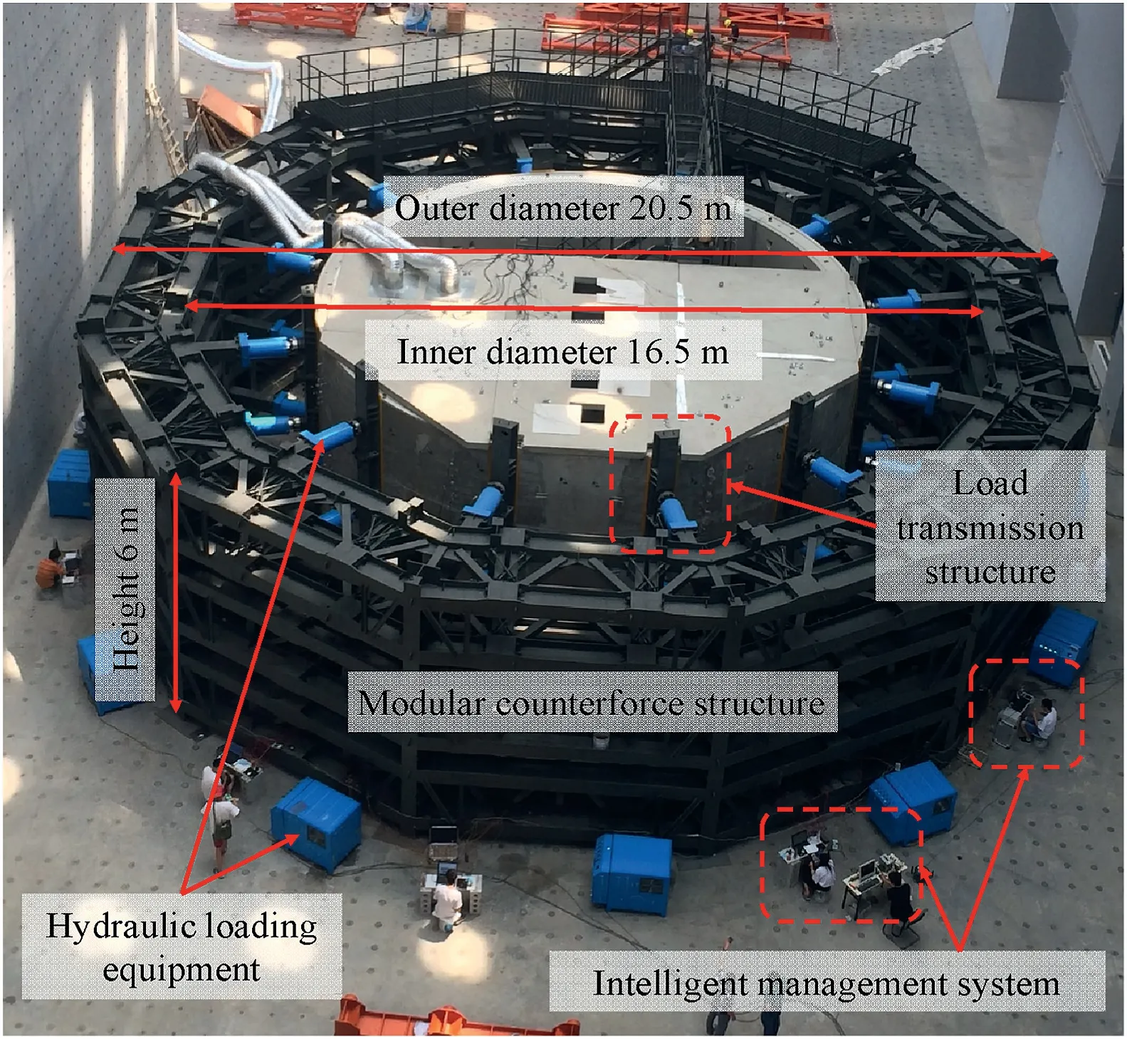
Fig.1.Prototype test system.
The load transmission structure(see Fig.3)consists of a loading beam,a hydraulic cylinder,a hinge,a cushion beam,a rubber mat,and other auxiliary parts.The loading beam connects the frame structure and the hydraulic cylinder.The hinge is the articulated component connecting the hydraulic cylinder and the cushion beam.The cushion beam can rotate around the central axis of the hinge to change the direction of the hydraulic cylinder.The cushion beam and the rubber mat can expand the contact area with the specimen,reduce the stress concentration in the loading area,and prevent premature failure of the specimen.
According to the type(size and shape)of the specimen,the test area can be adjusted within the range of 3-16 m by assembling different modular frame structural units and changing the length of the loading beam,which is suitable for the prototype test of the supporting structure with a cross-sectional area of 30-200 m2.Then,the number of loading points and the hinge angle can be adjusted to be suitable for the prototype test of the supporting structure of conventional shapes,such as circular,rectangular,straight wall arches and horseshoes or other shapes.Each floor of the modular counterforce structure is similar and can be split or combined into single-floor,double-floor and triple-floors,which can be used to conduct the prototype test of the single-ring,doublering and triple-ring supporting structures.
2.2.Hydraulic loading equipment
The hydraulic loading equipment (see Fig.4) comprises 12 hydraulic pump stations and 36 hydraulic cylinders.Each hydraulic pump station has three independent oil supply circuits.Each of these controls one hydraulic cylinder.Each hydraulic pump station and three hydraulic cylinders(an upper cylinder,a middle cylinder,and a lower cylinder)form a loading group.The rated output force of one hydraulic cylinder is 2000 kN,and the stroke is 600 mm.The hydraulic loading equipment can provide a maximum radial force of 72,000 kN and hold the load constant for up to 72 h.
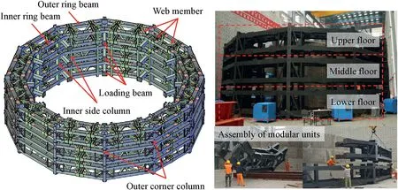
Fig.2.Modular counterforce structure.
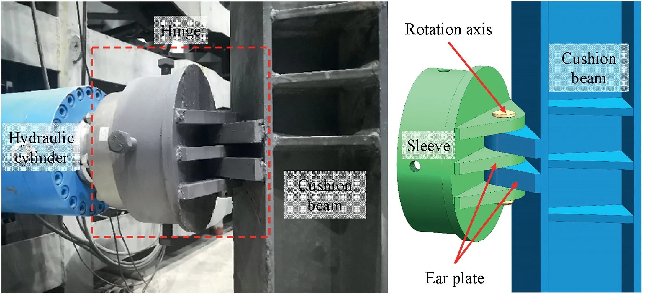
Fig.3.Load transmission structure.
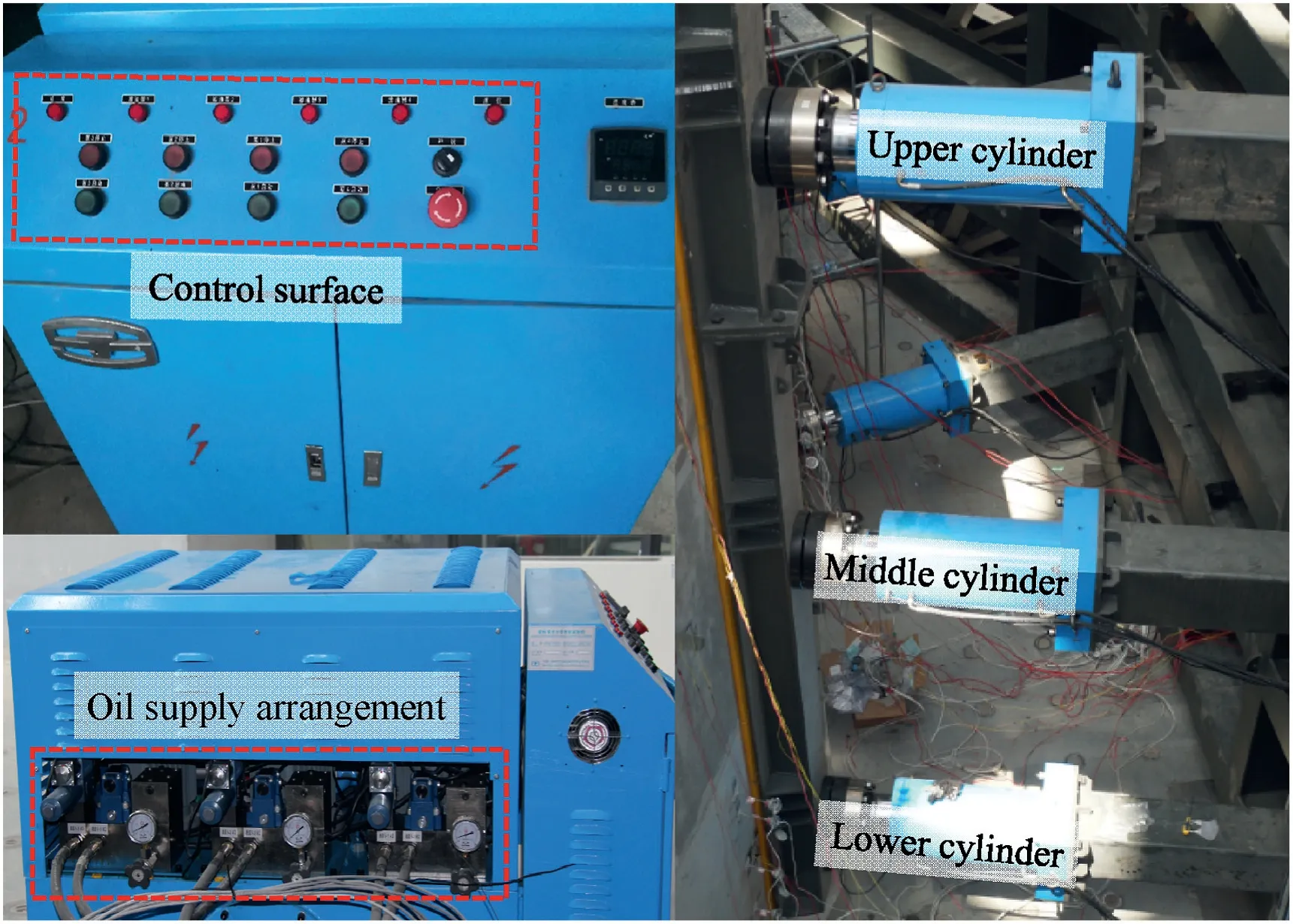
Fig.4.Hydraulic loading equipment.
2.3.Intelligent management system
The highlight of the intelligent management system is the mutual linkage and feedback between loading and monitoring,as shown in Fig.5.The intelligent management system can control hydraulic loading equipment through two closed-loop loading modes,i.e.load-and displacement-controlled modes.The resolution of the load-controlled mode is 1 kN,and that of the displacement-controlled mode is 0.01 mm.The control signal of each hydraulic cylinder is independent.Under the control of the intelligent management system,gradient loads,cyclic loads,and cross loads can be output to fit the burial depth,fatigue and unloading conditions of the tunnel.In addition,the intelligent management system integrates the data acquisition and exchange interfaces of vibrating wire type,resistance type,and optical fibre type monitoring equipment,which can also display and analyze the test data in real-time and predict the changing trend of various mechanical parameters.Based on the prediction results,the intelligent management system can actively adjust the loading mode to prevent overloading and underloading.These functions make the discrete loading and monitoring unified and coordinated,which is conducive to controlling the test results.
2.4.Noncontact deformation measurement system
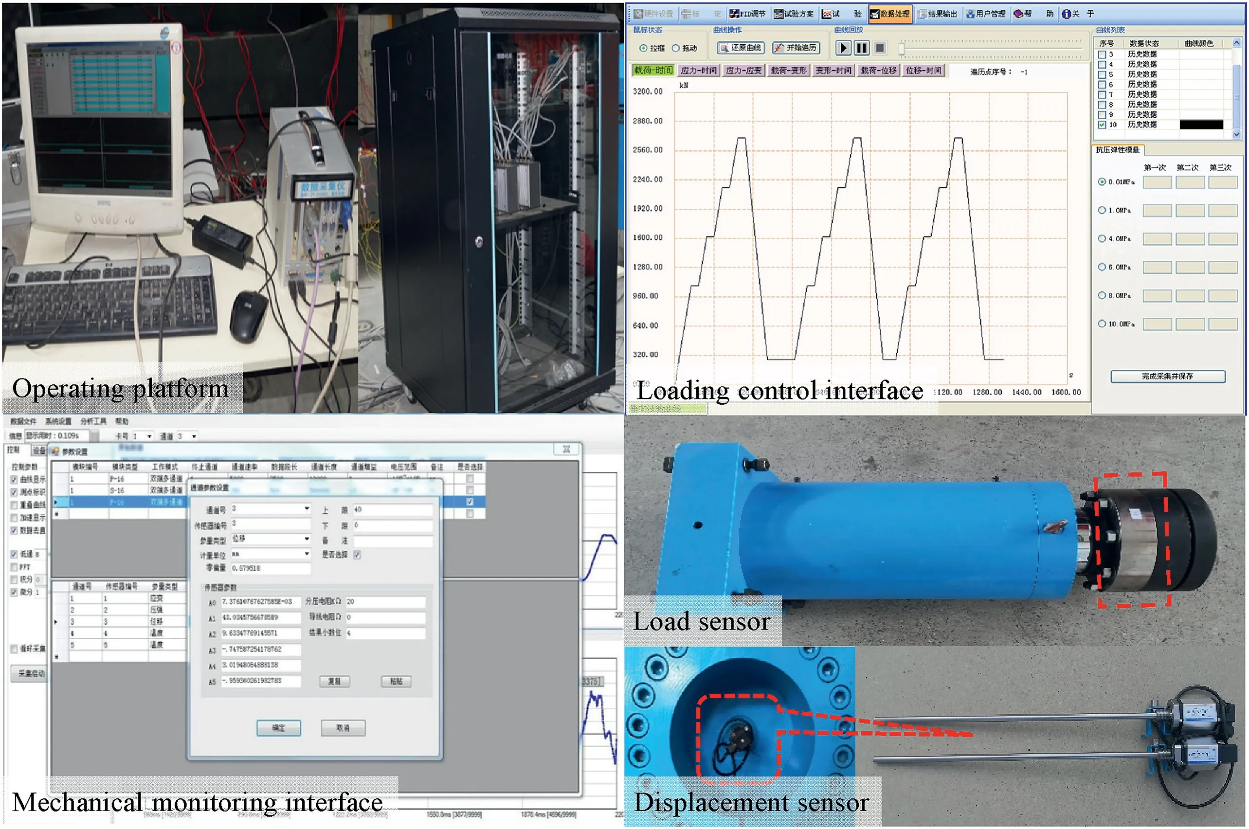
Fig.5.Intelligent management system.
The contact deformation measurement technology requires that the sensor should be placed on the surface or inside the specimen.If the sensors are arranged densely,then the mechanical properties of the specimen will be affected.If the sensors are placed sparsely,then the deformation characteristics of the specimen will be lost,especially during large-scale testing.Therefore,noncontact deformation measurement technology was developed (Zhu et al.,2017;Zou and Meng,2020).According to the principle of a unified datum,as shown in Fig.6,the noncontact deformation measurement technology effectively integrates the digital close-range measurement and the TS50 automatic measurement to obtain high-precision and continuously positioned deformation of the specimen without deploying too many sensors.
The digital close-up measurement makes the optical axis of the digital camera perpendicular to the plane of specimen deformation,keeps the internal and external orientation elements unchanged,and continuously takes multiple photos.When the specimen is deformed,parallax is generated between these photos and can be converted into specimen deformation.The TS50 automatic measurement is used as a supplement for digital close-range measurement and is mainly used to locate the deformation of the reference length to correct the digital close-up measurement.Thus,the noncontact deformation measurement technology can capture the deformation of the specimen and the modular counterforce structure during the testing process and correct the relative deformation between them to improve test accuracy.
3.Case application: mechanical behavior of the lining under fire
This case application relies on the shield tunnel project of the Beijing Metro,China.According to the survey and design data,the tunnel is located in the coarse sand and sandy pebble stratum.The lining specimen comprises six standard blocks,two adjacent blocks and a capping block,with an outer radius of 5.8 m and an inner radius of 5.25 m (Liu,2016;Wang,2016).
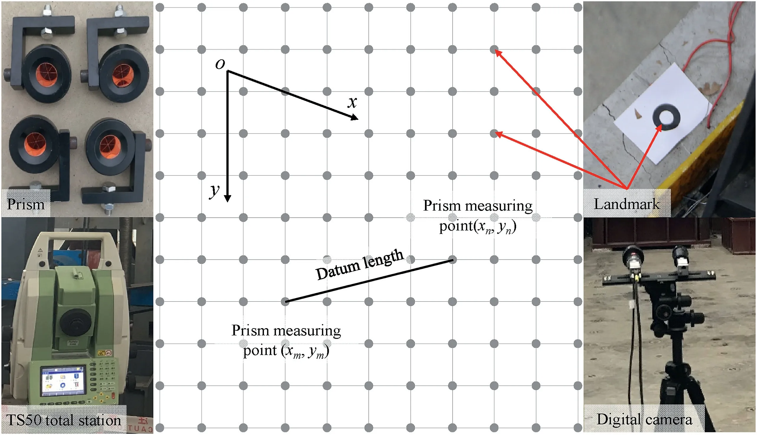
Fig.6.Noncontact deformation measurement technology.
3.1.Conversion of the stratum load
The test scenario is based on a possible tunnel fire and requires the mechanical condition of the lining specimen to be close to the actual working state.However,the actual stratum load is a uniformly distributed pressure,and the output load of the prototype test system is a concentrated force.The internal force of the lining is not entirely equal under the two loads.Hence,the stratum load needs to be reasonably simplified to meet the test requirements.
The bending moment is an essential criterion for judging whether the lining design is reasonable in the current tunnel design standard.Therefore,in this test,based on the principle that the bending moment of the characteristic section of the lining is equal,the stratum load is converted into the concentrated force output by the prototype test system through the numerical method.The numerical model is shown in Fig.7,and the conversion process of the stratum load is described as follows:
(1) Establish a two-dimensional plane numerical model of the tunnel and then excavate the tunnel and apply the lining.
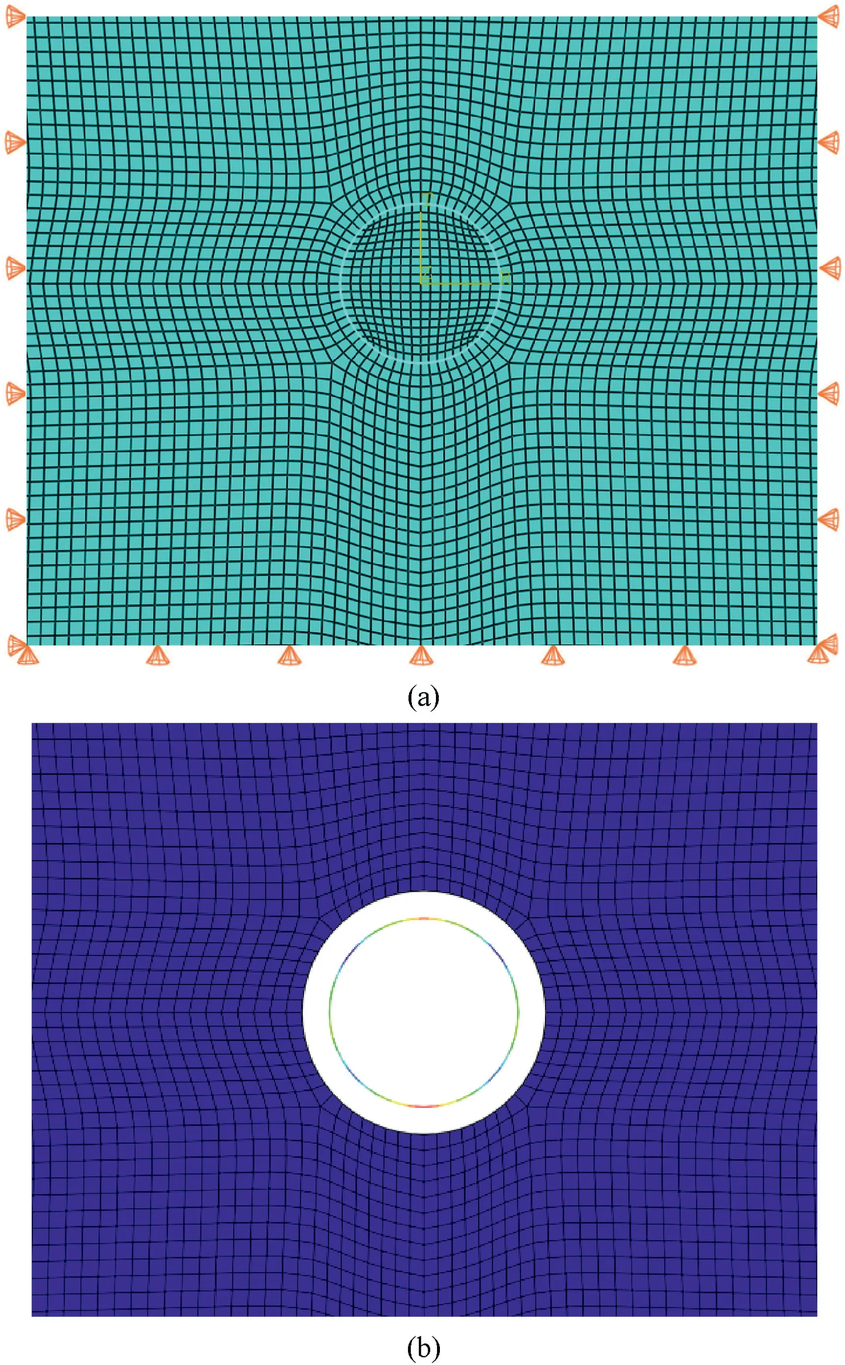
Fig.7.Numerical model of the tunnel: (a) Boundary constraints and meshing,and (b)Release of the stratum load.
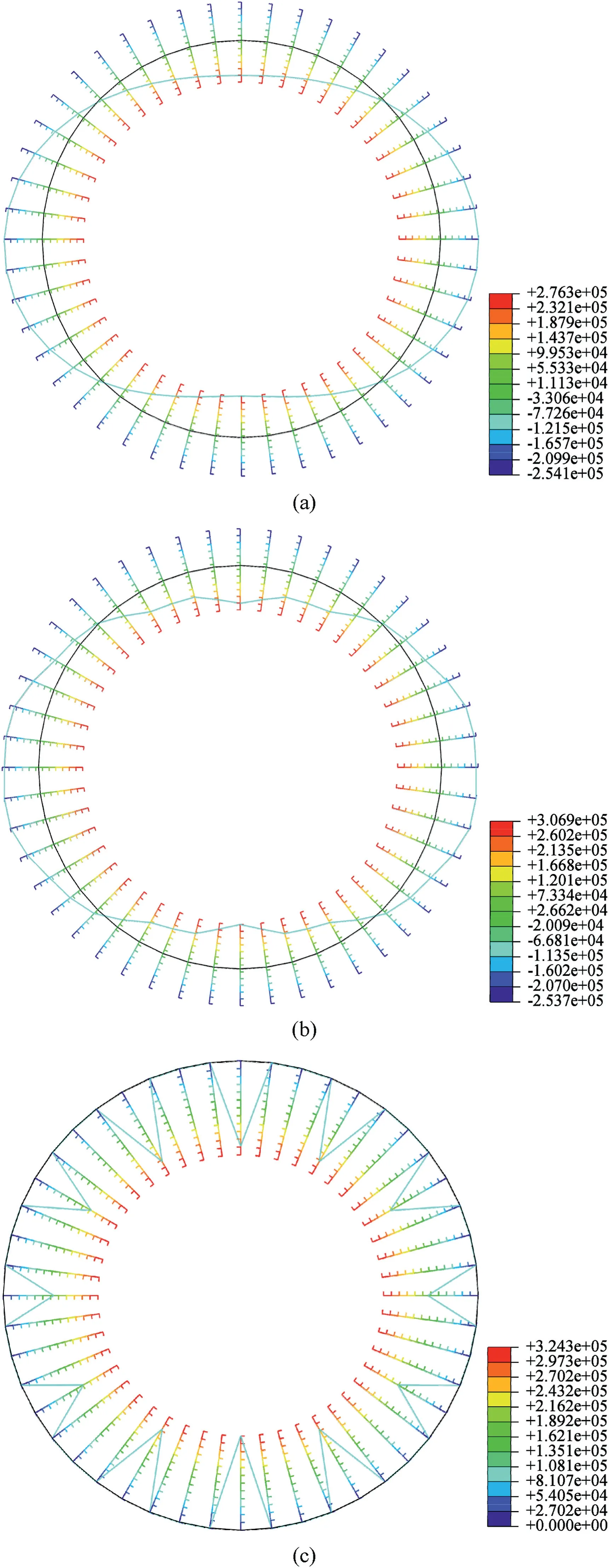
Fig.8.Conversion of the stratum load to the concentrated force:(a)Bending moment of the lining under the stratum load (unit: N m),(b) Bending moment of the lining under the concentrated force (unit: N m),and (c) Restraint force of the 12 control points (unit: N).
(2) Constrain the radial displacement of 12 control points of the lining (corresponding to 12 loading points of the prototype test system).
(3) Release the stratum load outside the lining to obtain the restraint force of the control point.
The conversion of the stratum load to the concentrated force is shown in Fig.8,which indicates that the bending moment distribution under the two loads is consistent.However,as shown in Table 1,due to the influence of the tunnel buried depth and the lining self-weight,the bending moment of the upper and lower symmetrical control points are unequal,especially at the vault and bottom control points.Except for these two points,the difference in bending moment of other control points is 6.02-14.22 kN m,and the difference rate is 4.48%-7.23%.The result shows that the method is feasible to convert the stratum load into the concentrated load.
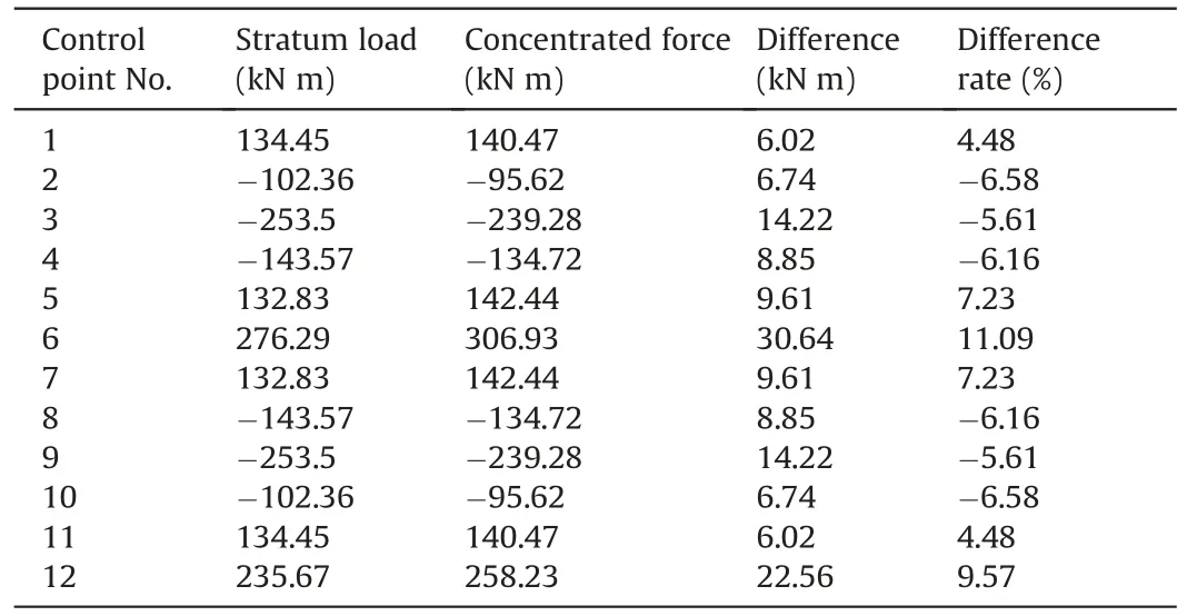
Table 1 Bending moment of the lining under stratum load and concentrated force.
The prototype test system requires the specimen to be placed horizontally,regardless of the weight of the specimen,thus the output load at the symmetrical loading points should be identical.Therefore,according to the restraint force of the control point and the lateral pressure coefficient of the stratum,the output load of the prototype test is divided into three groups,i.e.the vertical load ofFV=324 kN,the middle load ofFM=186 kN and the lateral load ofFL=162 kN,as shown in Fig.9.
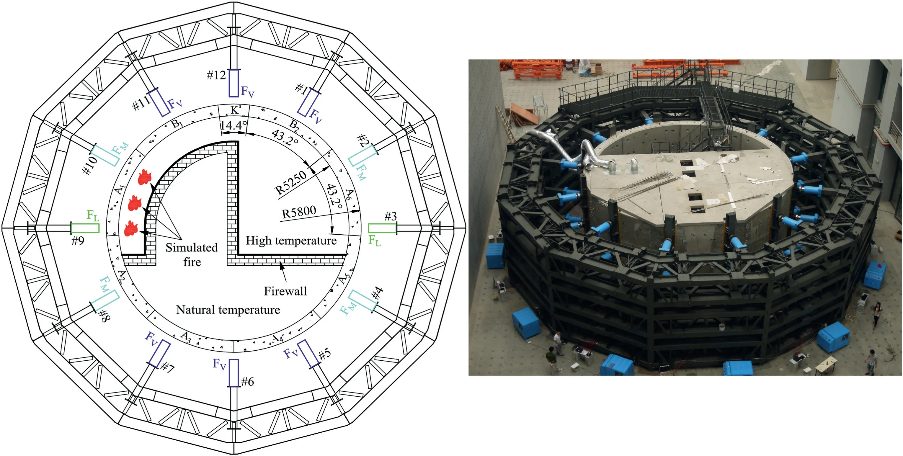
Fig.9.Dimensions and loading placement status of the lining specimen (unit: mm).
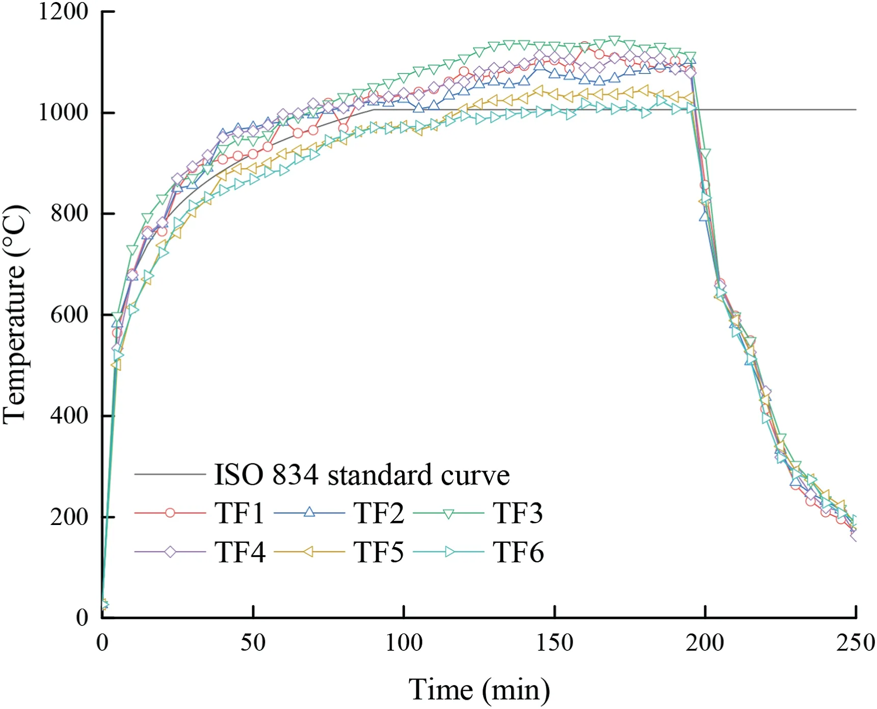
Fig.10.Temperature evolution of the fire source(TF1-TF6)and ISO 834 standard curve.
3.2.Experimental scheme
The experimental scheme is divided into following three stages:
(1) Stage I:The simulated stratum load is gradually applied at a constant rate untilFV=324 kN,FM=186 kN andFL=162 kN.
(2) Stage II:The simulated stratum load is maintained.The fire is simulated by following the ISO 834 standard curve(ISO 834-1:1999,1999) to heat the lining for 180 min,and the temperature exceeds 1000ºC.Then the simulated fire is extinguished,and the lining is cooled for 24 h.
(3) Stage III:The simulated stratum load continues to increase to study the mechanical behavior of the lining damaged by fire.
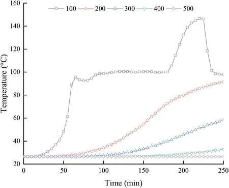
Fig.11.Temperature evolution of the lining at the depths of 100 mm,200 mm,300 mm,400 mm and 500 mm.
3.3.Temperature evolution analysis
The temperature evolution of the fire source and ISO 834 standard curve are shown in Fig.10.The simulated fire lasted for 195 min,and the temperature growth trend is consistent with the ISO 834 standard curve.At 70 min,the fire source temperature reached 1000ºC,lasted 125 min,and the maximum temperature reached 1144.9ºC.At 250 min (after the fire was extinguished for 55 min),the temperature near the fire source dropped to 160ºC-190ºC.This indicates that the simulated fire meets the test requirements.
Based on the non-uniform fire scenario,the fire source is arranged near the left side of the lining.The temperature evolution of segment A1 on the left side of the middle lining is most affected by the simulated fire,as shown in Fig.11.The initial temperature of the lining is an ambient temperature of 26.5ºC.At~15 min after the simulated fire started,the temperature of the lining at a depth of 100 mm began to increase exponentially.At~70 min,the temperature reached~100ºC and was maintained for~110 min.At~180 min,the temperature increased rapidly to 146.5ºC and then quickly dropped to~100ºC.The temperature at the depths of 200 mm,300 mm and 400 mm increased linearly,the highest temperatures were 91.6ºC,58.2ºC and 32.9ºC,respectively,and the temperature at a depth of 500 mm was maintained at an ambient temperature of 26.5ºC.As can be seen,the temperature of the lining is lower than that of the single-segment test damaged by fire(Caner and Böncü,2009;Yan et al.,2012,2015),which shows that the temperature of the lining is affected by the test scale and proves the necessity of carrying out the prototype test.
In addition,the temperature of the lining at a depth of 100 mm exhibited an evident temperature plateau after reaching 100ºC.The reason is that the free water in the lining concrete undergoes a phase change at 100ºC,which needs to absorb a large amount of heat,and the temperature will not rise until the free water is evaporated completely.As can be seen,the temperature of the lining is significantly affected by the water content;however,excess water content creates high vapour pressure that can exacerbate the bursting and spalling of the lining concrete (Lai et al.,2014).Therefore,the effect of water content on the lining subjected to fire damage needs further exploration.
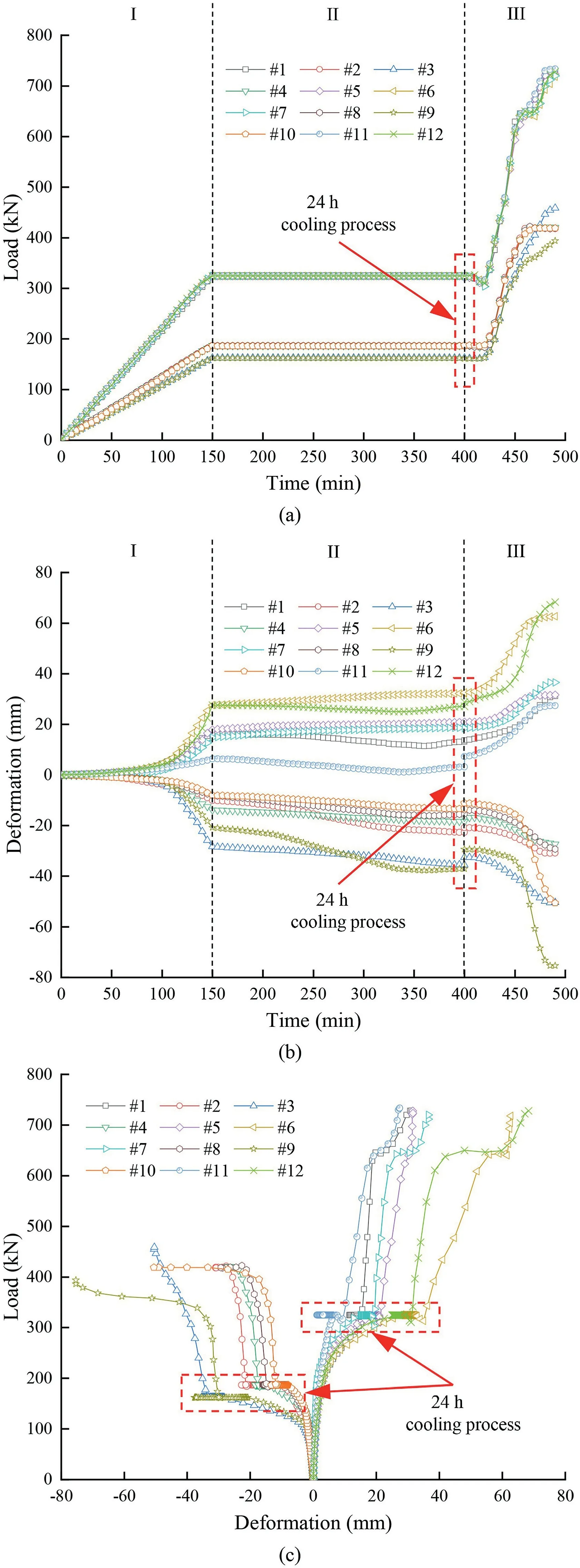
Fig.12.Load and deformation curves of the lining: (a) Time-load curve,(b) Timedeformation curve,and (c) Deformation-load curve.
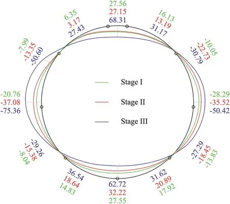
Fig.13.Deformation of the lining at the loading point (unit: mm).
3.4.Mechanical behavior analysis
The load and deformation curves of the lining are shown in Fig.12 and one can see that stage I lasted~150 min,stage II lasted~250 min,and stage III lasted~90 min.The deformation of the lining is defined as positive inwards and negative outwards.An independent analysis of each stage is described below.
At Stage I,the preset simulated stratum load increased uniformly untilFV=324 kN,FM=186 kN andFL=162 kN.The load is applied synchronously and smoothly,indicating that the prototype test system can apply the load accurately.The deformation of the lining increased linearly with the load.After this stage,as shown in Fig.13,the deformation of the vault (loading point #12) reached 27.56 mm,the bottom (loading point #6) reached 27.55 mm,the right waist (loading point #3) reached -28.29 mm,the left waist(loading point#9)reached-20.76 mm,and the deformation zone is elliptical in shape.There is no obvious crack on the lining surface,and only some joints open slightly,indicating that the lining is in the elastic bearing period.
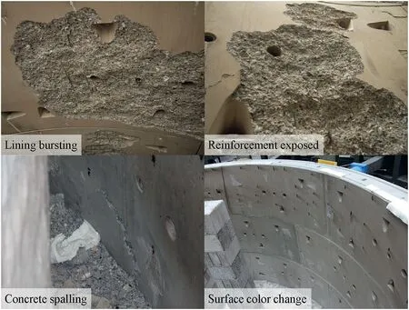
Fig.14.Deterioration of the lining by fire.
At Stage II,the simulated stratum load was always stable atFV=324 kN,FM=186 kN andFL=162 kN(including 24 h cooling process),indicating that the prototype test system can hold the load stably.At~10 min after the simulated fire started,there was a slight crackling sound from the lining,which gradually became louder and more frequent,and lasted for~30 min before it disappeared.After~20 min,the water seepage appeared in the lining near the fire source,gradually expanding to both sides,and the water vapour escaped from the joint and gradually disappeared after~100 min.After this stage,the concrete on the lining surface is seriously cracked and peeled off,and the reinforcement is exposed (see Fig.14).With the distance from the fire source,the colour of the lining surface changes from grey-white to dark red and then to cyan.
Moreover,the deformation of the lining also increased.The deformation of the vault(loading point#12)reached 27.15 mm,the bottom (loading point #6) reached 32.22 mm,the right waist(loading point#3)reached-35.52 mm,and the left waist(loading point#9)reached-37.08 mm,as shown in Fig.13.The deformation of the lining is flatter under simulated stratum loads and simulated fire degradation.However,after 24 h of the cooling process,the deformation of the lining caused by the simulated fire was partially recovered,indicating that the internal structure of the lining is still relatively complete and can remain stable.
At Stage III,the simulated stratum load was continuously increased on the lining damaged by fire,and the deformation of the lining increased rapidly.After this stage,the vertical,middle and lateral loads are 733.56 kN,420.62 kN and 458.61 kN,which are 2.26,2.26 and 2.83 times the preset simulated stratum load,respectively,indicating that the lining subjected to fire still has definite strength reserve.The deformation of the vault (loading point #12) reached 68.31 mm,the bottom (loading point #6)reached 62.72 mm,the right waist (loading point #3)reached -50.42 mm,and the left waist (loading point #9)reached -75.36 mm (see Fig.13).The deformation difference between the left and right waist is 24.94 mm,indicating that the damage to the lining caused by the simulated fire is visible.
As shown in Fig.15,after the test,there are many wide and deep cracks in the lining near the fire source,and there are apparent penetrating cracks and dislocations at the joints,showing that the radial and oblique cracks penetrate each other,forming a deep fracture zone.There are slight cracks in the lining away from the fire source,apparent openings at the joints,and some broken tenons.The mechanical behavior of the lining is significantly affected by the simulated fire.
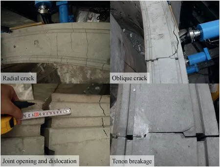
Fig.15.Failure characteristics of the lining.
4.Contribution of the developed prototype test system
As described in Section 1,there are still many limitations in the existing prototype test methods.In the self-balancing counterforce form and internal counterforce form,there are many restrictions on the shape and structural form of the specimen,and the loading must rely on the specimen.In the external counterforce form,these devices are developed for specimens of specific size and shape and are difficult to reuse.Besides,the loading and monitoring are separated.
The characteristics of the developed prototype test system are as follows:The shape and size of the modular counterforce device can be adjusted for the specimen.The load is large enough,and its application does not depend on the specimen.The loading mode and the monitoring sensor can communicate in real-time to realize the interaction between loading and monitoring.The deformation of the specimen can be continuously positioned with fewer highaccuracy sensors.The effective integration of these functions and technologies expands the application scope of the prototype test system,improves test accuracy,and promotes the development of model test research methods.
The equivalent stratum load exerted by the prototype test system is the concentrated force,which is derived from the reasonable simplified equivalence of the surrounding rock pressure,the surrounding rock elastic resistance,and the interaction between the surrounding rock and the supporting structure,and it is different from the actual stratum load.However,the case application proves the rationality of the equivalent stratum load and serves as a reference for the effective use of this prototype test system.
5.Concluding remarks
In this study,a multi-purpose prototype test system for tunnel supporting structure is developed,including a modular counterforce device,a powerful loading equipment,an advanced intelligent management system,and an efficient noncontact deformation measurement system.The functions of the prototype test system are adjustable size and shape of the modular counterforce structure,sufficient load reserve and accurate loading,multi-connection linkage intelligent management,and high-precision and continuously positioned noncontact deformation measurement.In the application case,the simulated stratum load is applied synchronously and smoothly and is held stably.The mechanical behavior of the lining during load-bearing,deformation and failure processes is described,which proves that the prototype test system is of practical significance.
Declaration of competing interest
The authors declare that they have no known competing financial interests or personal relationships that could have appeared to influence the work reported in this paper.
 Journal of Rock Mechanics and Geotechnical Engineering2023年2期
- Journal of Rock Mechanics and Geotechnical Engineering的其它文章
- On the critical particle size of soil with clogging potential in shield tunneling
- Experimental investigations on effects of gas pressure on mechanical behaviors and failure characteristic of coals
- Strength and deformation characteristics of irregular columnar jointed rock mass: A combined experimental and theoretical study
- Spatial distribution and failure mechanism of water-induced landslides in the reservoir areas of Southwest China
- Characteristics of electromagnetic vector field generated from rock fracturing
- Geotechnical investigation of low-plasticity organic soil treated with nano-calcium carbonate
