Influence of coupling asymmetry on signal amplification in a three-node motif
Xiaoming Liang(梁晓明), Chao Fang(方超), Xiyun Zhang(张希昀), and Huaping L¨u(吕华平)
1School of Physics and Electronic Engineering,Jiangsu Normal University,Xuzhou 221116,China
2Department of Physics,Jinan University,Guangzhou 510632,China
Keywords: network motif,synchronization,coupling asymmetry,signal amplification
1. Introduction
Designing an artificial structure that reproduces biological systems’ signal processing capabilities is challenging.[1–5]Considerable progress has been achieved in this direction.[6–10]One-way chains are the early proposed signal amplification structures in which the first site receives an input signal,and the last site outputs it.[11–13]With suitable noise and coupling strength,one-way chains can boost weak signals.Later,two-dimensional arrays were found to exhibit a similar noise-boosted amplification effect.[14,15]However,regular arrays are idealized coupling designs since most natural systems,especially neural networks, have complex structures.[16–23]Successive studies have shown that network structure significantly affects the signal amplification function.[24–27]For instance, small-world networks with long-range links may improve the network response to a weak input;[28,29]scale-free networks with star structures can generate a double resonance at the hub and leaf nodes.[30,31]
In addition to small-world and scale-free global features,many networks also exhibit local motif properties.[32,33]That is, some small subgraphs appear more often than in random networks. The three-node motifs with thirteen possible configurations are well-known network motifs in biological organisms ranging from bacteria and yeast to animals.[33–35]Thus, it is interesting to investigate the specific signal processing functions each motif can perform. To this end, Guoet al.studied the stochastic resonance in three-neuron feedforward motifs. They found that noise and coupling strength are two parameters that control the sensitivity and reliability of the motifs’responses to external signals.[36]Lianget al.reported that the feed-forward motif with two uncoupled input nodes and one output node has a specific function in regulating signal propagation.[37,38]This signal regulation effect is also observed in a three-node motif in which two input neurons have interactions.[39]

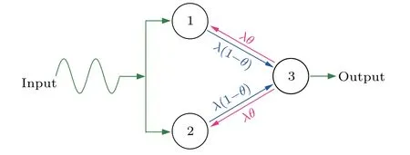
Fig.1.A sketch of three-node motif with bidirectional couplings,where node 1 and node 2 receive the input signal and node 3 outputs the signal. When the coupling asymmetry parameter θ =0, this motif returns to the feedforward motif.
Following this motivation, we study the signal amplification in a three-node motif with bidirectional couplings between the input and the output nodes. Specifically, we introduce a parameterθto represent the coupling asymmetry.[11,40]Whenθ=0.5,the couplings are symmetrical;whenθ <0.5,the couplings from the input nodes to the output node are stronger than vice versa.Thus,the motif returns to the feedforward motif with directional couplings whenθ=0[see Fig.1].We find that whenθis small but nonzero,i.e.,the output node feeds back a small influence on the input nodes, the signal response of the motif is amplified, and the coupling interval for signal amplification is expanded,displaying a double resonant signal response. We show that the asymmetrical coupling structure due to small feedback allows the motif to go through two distinct synchronization transitions, resulting in double resonance. We finally give a theoretical analysis to confirm our numerical results. We hope these findings will contribute to a deeper understanding of the relationship between motif structure and signal processing functions.
2. Model
We start with the overdamped bistable oscillator with a double-well potential,which is often used as a baseline model for signal amplification.[41–44]The motif of three bistable oscillators has the following form:

whereλis the coupling strength,andθis a parameter describing the coupling asymmetry between nodes. Therefore,θ=0 andθ=1 represent two different unidirectional coupling configurations. Depending on the periodic input signalAsin(ωt),individual oscillators (λ=0) either vibrate in one potential well or switch between the wells.The transition from one-well vibration to well-to-well oscillation occurs atAc=.[41]Without losing generality,we consider a subthreshold signal ofω=π/50 andA=0.1<Acthroughout our investigation.
For simplicity,we measure the signal response of the motif using the amplitude of the output node[24,25]

Thus,ifG <1,the motif attenuates the input signal while amplifying it ifG >1. In addition, we quantify the spatial synchronization of the motif using the order parameter[45,46]

wheren+andn-are the number of oscillators in the positive well atxs=1 and the negative well atxs=-1, respectively.Herexs=±1 are two stable fixed point of the overdamped bistable oscillator. Whenρ=0, the motif is asynchronous,with two nodes vibrating in the positive and negative potential wells and the third switching between them. Whenρ=1,the motif is synchronous, and all three nodes vibrate in the same well.
In numerical simulations, the initial states of the three nodes are chosen fromxs=±1, where two input nodes are assigned with opposite signs to facilitate signal amplification,i.e.,x1(0)=-x2(0).[37,38]
3. Simulations
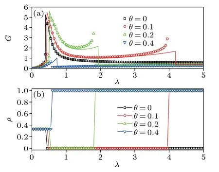
In Fig.2(a), we show the signal response of Eq.(1)as a function of the coupling strength for different coupling asymmetries. Atθ=0, the motif generates a resonance-like signal amplification (G >1) for intermediate coupling strengthλ, consistent with the findings in Refs. [38,39]. As the coupling asymmetry increases toθ=0.1, the motif produces a double resonance,with the first resonance occurring at a small coupling strengthλc1as in the case ofθ=0, and the second resonance occurring at a relatively large coupling strengthλc2.The signal response within the coupling interval (λc1,λc2) is greater thanθ=0. Continuing to increase the coupling asymmetry toθ=0.2,the two resonance peaks slightly rise while the coupling interval between the double resonance peaks significantly shrinks. However, further increasing the coupling asymmetry(e.g.,θ=0.4)will eliminate the double resonance effect and return to the single resonance with a damped signal response(G <1). Therefore,small feedback(θ/=0)from the output node to the input nodes may optimize the signal amplification of the feedforward motif (θ=0). Meanwhile,figure 2(b)plots the spatial synchronization corresponding to the signal amplification as described in Fig. 2(a). In the caseθ= 0, the order parameter drops fromρ= 1/3 toρ= 0 as the coupling strengthλexceedsλc1, suggesting that the resonance appearing atλc1is induced by a synchronization–asynchronization transition.In the presence of coupling asymmetryθ=0.1 andθ=0.2,the order parameter drops toρ=0 atλc1,similar to that ofθ=0;but after that point it jumps toρ=1 atλc2. This jump indicates that the second resonance atλc2arises from an asynchronization–synchronization transition.However,the order parameter directly transits fromρ=0 toρ=1 atλc1for the large coupling asymmetryθ=0.4,indicating that high levels of synchronization harm signal amplification.

Fig.2. Signal response G in panel(a)and order parameter ρ in panel(b)as a function of the coupling strength λ for coupling asymmetry θ =0,0.1,0.2,and 0.4. Dashed lines in panel(a)denote the predictions of Eq.(20).
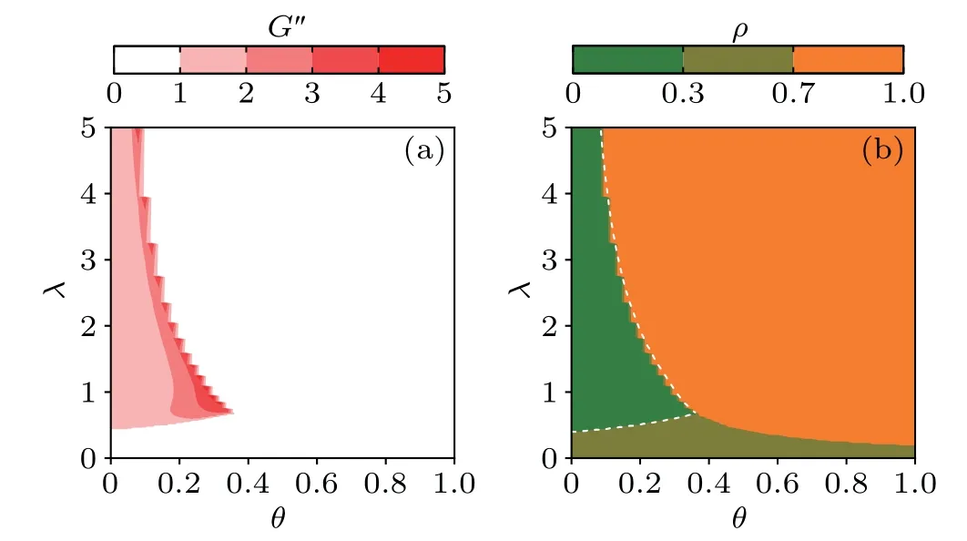
In Fig. 3(a), we present the signal response for different pairs of coupling strength and the coupling asymmetry. For a better comparison, we normalize the signal response by dividing its value atθ=0,i.e.,G′=G(θ)/G(θ=0). As a result,G′>1 means that the output node’s feedback(θ >0)enhances the signal amplification.As seen in Fig.3(a),the signal responseG′>1 emerges when the coupling strength and the coupling asymmetry are over a pair of critical valuesθcandλc. In addition, there are two different relationships betweenθcandλc. Specifically,θc~λc1for small coupling strength andθc~for large coupling strength. That is, relatively large feedback may amplify the input signal for a small coupling strength,whereas small feedback may realize the signal amplification for a large coupling strength. Furthermore, figure 3(b)presents the order parameter corresponding to the signal response shown in Fig.3(a). There are three regimes in the parameter space(θ,λ): partial synchronization withρ=1/3(regime I),asynchronization withρ=0(regime II),and synchronization withρ=1(regime III).Clearly,regime II corresponds to the plateau withG′>1 observed in Fig. 3(a), and its boundaries are exactly the relationships betweenθcandλc1andλc2.

Fig.3. Normalized signal response G′ (a) and order parameter ρ (b) as a function of the coupling strength λ and the coupling asymmetry θ. Dashed lines in panel(b)denote the predictions of Eqs.(10)and(15).
4. Analysis
Denoting the average activityy=(x1+x2)/2 and synchronization errorz= (x1-x2)/2 of the two input nodes,equation(1)turns into

Because the input nodes are driven by the same force, the amplitude of the synchronization error is much smaller than the average. Accordingly, we may assume ˙z= 0 and getz2=1-3y2-θλandz=0 from Eq. (5). These two distinct solutions correspond to asynchronization (λ <λc2) and synchronization(λ ≥λc2)of the two input nodes,respectively.
In the case of asynchronization(z2=1-3y2-θλ),equation(4)simplifies to

Similarly,we may assume ˙y=0 and 8y3=0 sinceyis small and less thanx3whenλ ≪λc2. Then equation(7)becomes

Substituting it into Eq.(6)yields

whereα=λ((1-θ)(3λθ-2)+(1-λθ))/(1-λθ) andβ=λ(1-θ)/(1-λθ). WhenA=0, equation (9) has two stable fxied points=±forα >0 and one stable fxied point=0 forα <0. Letλ0be the critical coupling strength forα=0.WhenA/=0,the periodic signalβAsin(ωt)transits from subthreshold to suprathreshold if the coupling strength exceeds a critical valuesatisfying

As Fig.2(a)shows,the criticalof Eq.(10)fits the numerical data. Since the periodic signal remains subthreshold forλ <,the output node will vibrate aboutand its approximate solution can be derived using the linearization method as

whereφ1=arctan(ω/2α)is the phase shift. Forλ ≥,the periodic signal is suprathreshold which forces the output node to oscillate around=0. In this situation, the approximate solution of Eq.(9)is as follows: assuming the periodic signal as constants±βAdue to shortω,
(i)whenα >0,i.e.,λ <λ0,
(ii)whenα ≤0,i.e.,λ ≥λ0,

In the case of synchronization(z=0),the three nodes vibrate in the same potential well. To obtain the analytical coupling strengthfor motif synchronization, we put Eq. (13)into Eq.(7)and find

According to Eq. (14), the average activityyoscillates about the stable fixed pointy*=0 under a subthreshold force while it diverges under a suprathreshold force.[47]This is because Eq. (14) is derived from the asynchronization conditionz2=1-3y2-θλ; whenλ ≥, the asynchronization condition is no longer satisfied and thus equation (14) becomes incorrect (divergence). Following Eq. (10), the coupling strengthfor the signal in Eq. (14) changing from subthreshold to suprathreshold satisfies

Figure 2(a) shows the estimations of Eq. (15), which are slightly bigger than the numerical valuesλc2. The reason for this is that when the coupling strength approachesλc2,the motif tends to synchronize,i.e.,y=x3,so the approximations of ˙y=0 and 8y3=0 are inaccurate in Eq.(7),giving rise to the large analytical.
Next,we substitutez=0 into Eq.(4)to obtain the average activityyforλ ≥,which takes the form

When the three nodes are in one well,the value ofx3is smaller thanysince the output node has no external periodic drive signal. For this reason,we may supposex3=±1 in Eq.(16)and obtain the approximate solution of the average activityyas

whereφ2=arctan(ω/(2+λθ)) is the phase shift. Putting Eq.(17)into Eq.(6)gives

Its approximated solution is

whereφ3=arctan(ω/(1+λ-λθ))is the phase shift.
Combining Eqs. (11)–(13) and (19), we can obtain the analytical signal response of Eq.(1)as

whereIis the amplitude of Eq.(19). Figure 2(a)shows the analytical results of Eq.(20), which correctly predict the aforementioned double resonance. Note that the double resonance peaks are located at the dynamic transition pointsand.This can be explained as follows. The periodic signals in Eqs. (9) and (14) become suprathreshold atand. In the former case, the suprathreshold signal allows the output node to leave the potential well,decreasing the spatial synchronization. In the latter case, the suprathreshold signal drives the input nodes to synchronize with the output node,increasing the spatial synchronization.Both cases imply that the motif is very sensitive to external signals in the vicinity of the synchronization transition points.
5. Summary
In conclusion,we have studied the signal amplification in a three-node motif composed of overdamped bistable oscillators,focusing on the effect of asymmetrical couplings between the input and output nodes. We have shown that the motif may generate a double resonant response to a subthreshold signal when the couplings from the output node to the input nodes are weaker thanvice versa. We have found that the asymmetrical coupling-induced double resonant signal response is higher than the single resonant signal response in the feedforward motif with only unidirectional couplings from the input nodes to the output node. We have revealed that two different spatial synchronization transitions account for the emergence of the double resonance in the asymmetrically coupled three-node motif. Motifs are the basic building blocks of complex networks. On the one hand, our findings contribute to the knowledge of the signal amplification mechanism of the three-node network motifs. On the other hand, they provide a simple yet instructive description of the network structurefunction relationship.
Acknowledgment
Project supported by the National Natural Science Foundation of China(Grant Nos.12175087 and 12105117).
- Chinese Physics B的其它文章
- The coupled deep neural networks for coupling of the Stokes and Darcy–Forchheimer problems
- Anomalous diffusion in branched elliptical structure
- Inhibitory effect induced by fractional Gaussian noise in neuronal system
- Enhancement of electron–positron pairs in combined potential wells with linear chirp frequency
- Enhancement of charging performance of quantum battery via quantum coherence of bath
- Improving the teleportation of quantum Fisher information under non-Markovian environment

