CNT toughened aluminium and CFRP interface for strong adhesive bonding
Gng Hn ,Bo Tn ,Fi Chng ,Binhu Wng ,Y-Kwong Long ,Xiozhi Hu,*
a Department of Mechanical Engineering,University of Western Australia,Perth,WA,6009,Australia
b Department of Chemical Engineering,University of Western Australia,Perth,WA,6009,Australia
c Shaoxing Baojing Composite Materials Co.,Ltd,Shaoxing,312073,PR China
d School of Materials Science and Engineering,Southwest University of Science and Technology,Mianyang,621000,PR China
e Key Laboratory of Road Construction Technology and Equipment,MOE,Chang'an University Xi'an,710064,PR China
Keywords:Shear bond strength Interfacial toughening CNT Resin pre-coating (RPC)Chemical surface treatment Aluminium/CFRP Laminate
ABSTRACT This study presents a simple technique for strengthening the adhesive-bond strength between aluminium (Al)substrate and carbon fibre reinforced polymer (CFRP) utilising resin pre-coating (RPC) with carbon nanotubes(CNTs).The CNT-containing RPC solution with 90 wt%acetone and 10 wt%resin(without hardener)was applied onto Al substrates,where micro-/nano-vertical channels had been created by chemical or mechanical surface treatments to accommodate CNTs.RPC was able to fill all micro-/nano-cavities over the Al substrate surface,then CNTs were pulled into those vertical micro-channels by the capillary action generated from acetone evaporation.Normal epoxy adhesive (resin +hardener) was applied after the CNT-containing RPC treatment.CNTs bridging across the interface between the adhesive joint and Al substrate and sealing of micro-/nano-cavities by RPC effectively enhanced the interfacial shear bond strength between the Al substrate and CFRP by 30–100%depending on the Al substrate surface profiles.Al substrates with two different chemical treatments were compared in this study for the effectiveness of CNT interfacial reinforcement.Results from a steel substrate after sandblasting were also included for comparison.
1.Introduction
Carbon nanotube(CNT)as a key focus of nano-materials science has been studied for many years[e.g.[1,2]].Nowadays,it is expected to see more and more industrial applications of this unique nano-material.CNT typically with a nano-sized diameter and micro-scale length from 1 to 10 μm is a perfect choice for strengthening narrow adhesive joints between carbon-fibre reinforced polymers(CFRP)and aluminium(Al)alloy substrates,and interfaces in laminar CFRP structures commonly employed in the aviation and automotive industries[3].
The relatively weak interface between the Al substrate and ultra-thin adhesive joint (followed by CFRP) is always a concern for the adhesive bond strength of Al/CFRP structures.Typical epoxy adhesive bonding between Al and CFRP may involve different substrate preparations(cleaning,chemical treatment,sandblasting or primer coating),followed by the final adhesive bonding.While the interfacial bond strength has been improved by those commonly used substrate preparation methods,the reality is that there is still no“Z-direction”reinforcement across the interface between the Al substrate and adhesive joint.It is perceivable fibre bridging across the interface between the Al substrate and adhesive joint will be beneficial for eliminating any potential premature adhesive failure along the interface.Particularly,it has been proven that Z-pin and stitching [e.g.[4–6]] are effective against delamination or interfacial cracking in laminar CFRP.Although Z-pin and stitching cannot be adopted directly for adhesive bonding between Al and CFRP,quasi-Z-directional fibre bridging against interfacial cracking can still be realised by suitable substrate preparations.Keeping the simplicity of common adhesive bonding,this study explores a plausible technique for interfacial fibre bridging or CNT “Z-pin” in conjunction with pre-made micro-/nano-sized cavities or channels in Al substrates using either chemical or mechanical methods [7–9].
The simple CNT-containing resin pre-coating (RPC) technique,presented in this study,can be conveniently applied in any laboratory for small test samples and adopted on-site for large structures after chemical or mechanical preparations of substrates.This simple and quick intermediate RPC step is beneficial as it does not cause any noticeable delay and complication for the process of adhesive bonding.Yet,the shear bond strength has been consistently increased by 30%–100%,depending on the substrate surface profiles.In this study,Al substrates prepared by two different chemical treatments and a steel substrate prepared by sandblasting are used to confirm the CNT-PRC adhesive bonding method.
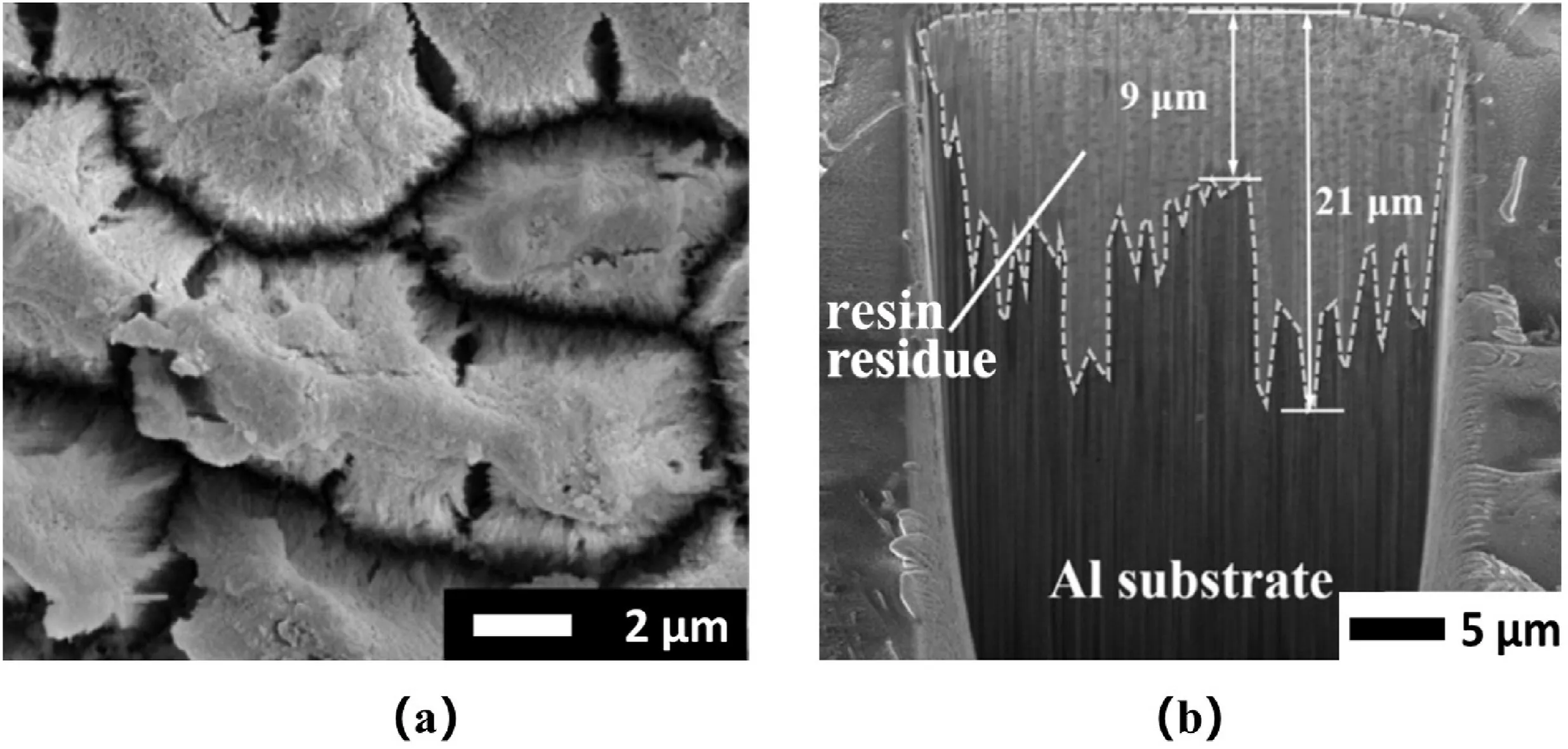
Fig.1.(a)Top view of chemically treated Al(CHEM1)substrate surface with vertical channels.The viscous epoxy adhesive may not fill in the micro-cavity tips.(b)FIB exposed the side view,showing depths of the vertical channels are around 10–20 μm,and the micro-channels have been filled all the way to the tips by the unique RPC process.
2.CNT “Z-pins” across Al substrate with micro-channels positioned by capillary action
2.1.CNT dispersion in resin pre-coating (RPC) solution
For practical applications of CNTs interfacial toughening for strong adhesive bonding,the following three conditions need to be satisfied.(1)There should be a simple method for CNT dispersion,which can be carried out with minimum equipment requirements and could be easily adopted on-site.(2)Applications of CNT for adhesive bonding should be simple so that engineers without any special research skills can still use the well-studied nano-material for real structures.(3) CNT toughening has to be noticeably effective,e.g.,consistently improving the adhesive bond strength by at least 20–50% or higher,whether it is done by an experienced researcher in the laboratory or a practical engineer working on site.This study intends to provide tentative solutions for the above three conditions.
Firstly,the dispersion of CNT in an acetone-diluted resin solution(e.g.90 wt% of acetone and 10 wt% of resin without hardener) is simple,which can be done by simple mechanical stirring for a few minutes.A“perfect CNT dispersion” in this resin pre-coating (RPC) solution is unnecessary for common adhesive bonding,so 5–10 min of mechanical dispersion is more than sufficient.Furthermore,the CNT-containing RPC solutions can be pre-made and tailored for specific requirements.Acetone evaporation from the CNT-containing RPC solution is fast,and the mechanical properties of the remaining resin are not affected[10].
Secondly,the CNT-containing acetone-rich RPC solution can be conveniently coated over Al substrates through either spraying or brushing.That is instead of mixing CNT in a viscous epoxy adhesive(resin and hardener mixture),the CNT-coating or distribution over the Al substrate surface is done using the low viscous RPC solution(90 wt%of acetone and 10 wt%of resin without hardener).The RPC process has two distinct roles;(1)to fill all micro-/nano-surface and sub-surface cavities and channels and wet the entire substrate surface,and (2) to pull CNT into those micro-channels from the capillary action during the acetone evaporation process.Note that the RPC solution contains 90 wt%acetone and only 10 wt%resin.
Thirdly,it has been tested and confirmed that even RPC by itself is effective for the adhesive bond strength improvement for metal substrates with various surface conditions[11–13].Fibre bridging from CNT just makes the RPC method even more effective for additional bond strength improvement [8,9].All the relevant studies on adhesive bond strengths with various substrates show that the interfacial bonding strength improvements are at least around 30% or higher.Considering CNT-coating over Al substrates can be easily done using the RPC solution,the proposed CNT-containing RPC method is simple,beneficial and fully justified in applications.
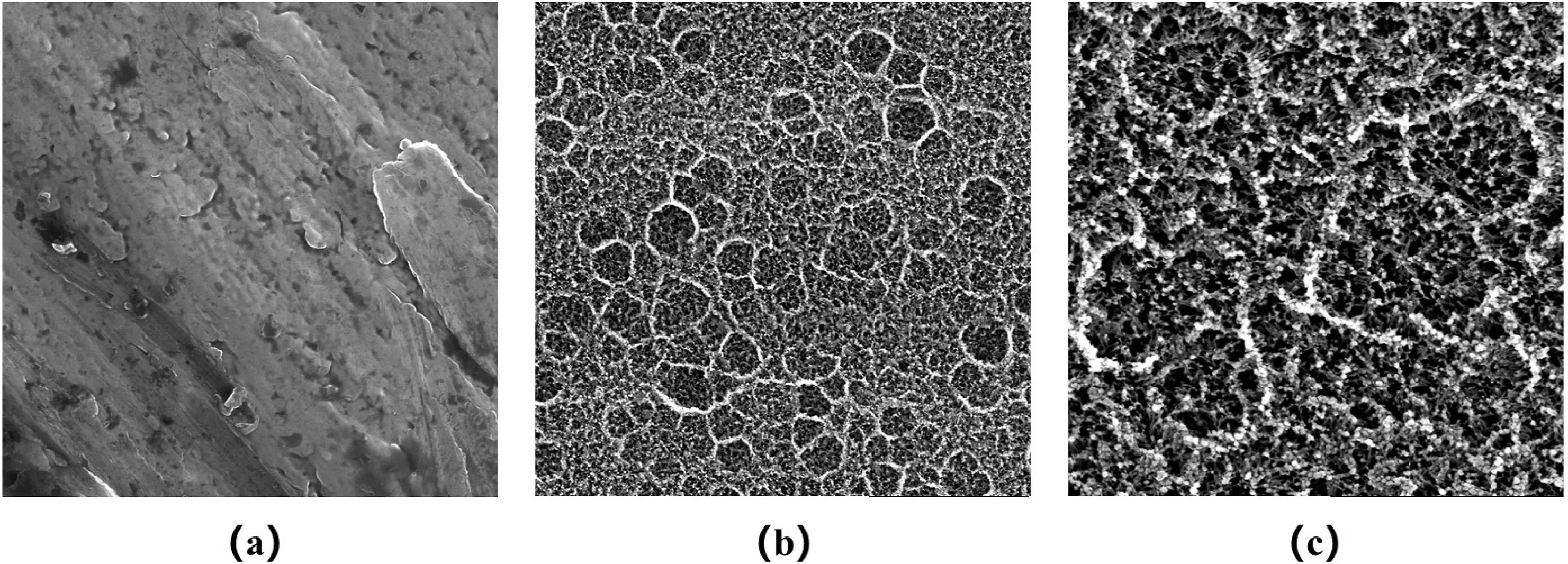
Fig.2.(a)original surface,and then(b)and(c)Top view of phosphoric acid anodised Al(CHEM2)with porous structures with 50–200 nm diameters.Based on the micro-surface features,CNT “Z-pins” are most likely less effective for CHEM2 in comparison to CHEM1.
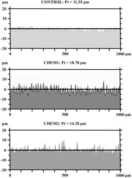
Fig.3.Height profiles of CONTROL,CHEM1 and CHEM2,where the maximum x-scale range =1000 μm and maximum y-scale range =40 μm.
It should also be mentioned that it has been proven mathematically that fibre bridging can still be effective against the opening mode(Mode-I) crack propagation in CFRP even if short or micro-length fibres at the ply interface are not perpendicular to the crack face[14].For shear bond strengths(Mode-II),perfectly vertical“Z-pins”are even less important,or necessary.As long as the micro-cavities are deep enough to accommodate CNT“Z-pins”,creating perfectly vertical micro-/nano-channels on the Al substrates is not required.
2.2.Two Al substrates prepared by two different chemical treatments
To concentrate on the effectiveness of CNT interfacial toughening,three different surface profiles(Al substrates with two different chemical treatments,and one steel substrate with sandblasted surface finish) are examined and compared in this study.That is the main emphasis of this study is on the surface microstructures and their effects on CNT interfacial toughening.
Two chemical treatments of the Al substrate (6060 T5 aluminium),sulfuric acid,sulfuric acid-oxalic acid and sulfuric acid-oxalic acid-iron sulphate(CHEM1)[15]in Fig.1,and phosphoric acid electrolyte(20 wt%) (CHEM2) in Fig.2 are considered in this study.The material details and detailed chemical treatment process are described in Section 3.
The top surface view of the CHEM1 treated Al substrate surface is shown in Fig.1(a),and the side surface exposed by focus ion beam(FIB)is shown in Fig.1(b).The depth of those vertical channels varies from around 10 to 20 μm while their tip width is around 1 μm.That is those micro-channels are big enough to accommodate various CNTs with diameters from 10s of nano-meters(typical multi-wall CNT)to one or two hundred nano-meters (e.g.helical CNT).The top outer alumina surface layer of the chemically-treated Al substrate is strong,so the surface features are perfect for accommodating potential CNT“Z-pins”.It should be mentioned that the tips of those micro-channels have been filled completely by the epoxy adhesive using the RPC process as shown in Fig.1 (b),while this may not be possible with direct applications of regular viscous epoxy adhesives.
The surface profile from CHEM2 in Fig.2 is very different to that in Fig.1.Instead of deep vertical micro-channels,the surface features in Fig.2 are fairly smooth but having many micro-/nano-pore structures.Those shallow micro-/nano-pore structures from CHEM2 vary between 50 and 500 nm,which may not be as effective as CHEM1 surface features as far as vertical CNT Z-pins are concerned.Clearly,the differences in the surface profiles between the Al substrates in Figs.1 and 2 can provide useful information on the effectiveness of CNT interfacial toughening within the epoxy adhesive joint.
Surface variations or height differences of peak valley (Pt) for different Al surfaces,including CONTROL,anodised by CHEM1 and CHEM2,are measured and shown in Fig.3.The height difference for the untreated Al is 11.55 μm while it is 18.78 μm for CHEM1 and 14.28 μm for CHEM2,respectively.It is more meaningful to consider those Pt numbers in Fig.3 together with the local surface conditions,i.e.whether the peaks and deepest valleys are close to each other.If they are close to each other as for the CHEM1 condition,it is more likely to put CNT Z-pins into those vertical micro-channels.
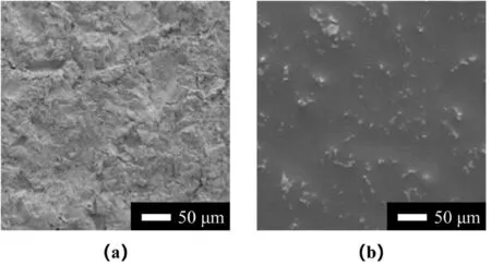
Fig.4.(a)For comparison,a normal sandblasted steel surface[16],and(b)all micro-cavities have been filled after RPC.The substrate wettability is improved since the surface remains wet (thin resin coating only and no hardener).Air entrapment in sub-surface micro-cavities is avoided in final adhesive bonding.
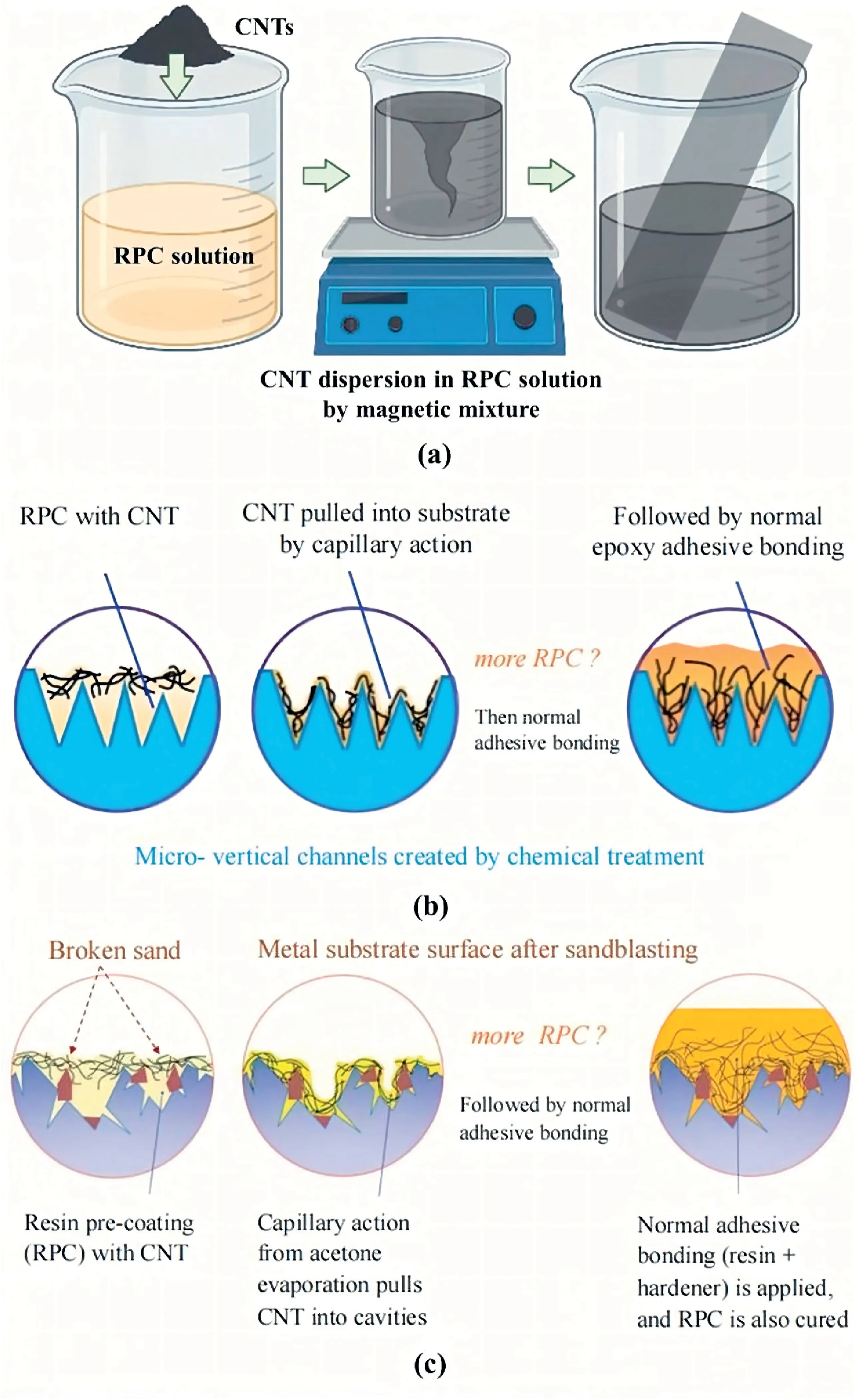
Fig.5.(a) CNT was well dispersed in RPC solution around 1 wt% (compared to the net resin).All surface-modified metals,including anodised Al and sandblasted steel,were soaked into CNT-containing RPC solution for 30s.(b) The CNT-containing RPC solution is applied onto the chemically treated Al substrate surface.During the process of acetone evaporation,CNTs are pulled into the microchannels.Standard epoxy adhesive(resin +hardener) is applied on the Al substrate normally for adhesive bonding.(c)The CNT-containing RPC solution can also be applied onto a sandblasted Al substrate with micro-cavities for similar CNT-bridging effects along the interface between the Al substrate and adhesive joint.Broken sand particles embedded in the metal substrate are also fully coated by the RPC process.
For comparison,a mild steel substrate with a sandblasted surface finish[16]is shown in Fig.4(a).The smooth surface in Fig.4(b)is“wet”,covered by the ultra-thin resin coating left by the RPC process.Changing the acetone/resin ratio,e.g.from the current 90 wt%acetone and 10 wt%resin to 95 wt% acetone and 5 wt% resin,will produce a thinner resin coating after the complete evaporation of acetone.However,as exposed by the FIB micrograph in Fig.1(b),the most important RPC feature underneath the smooth surface of Fig.4 (b) is that all micro-cavities have been filled by resin,and there are no micro-air pockets even at the tips of those micro-/nano-cavities.It may not be the case for a normal epoxy adhesive bonding since some degree of air entrapment at the tips of micro-/nano-cavities may not be avoidable.
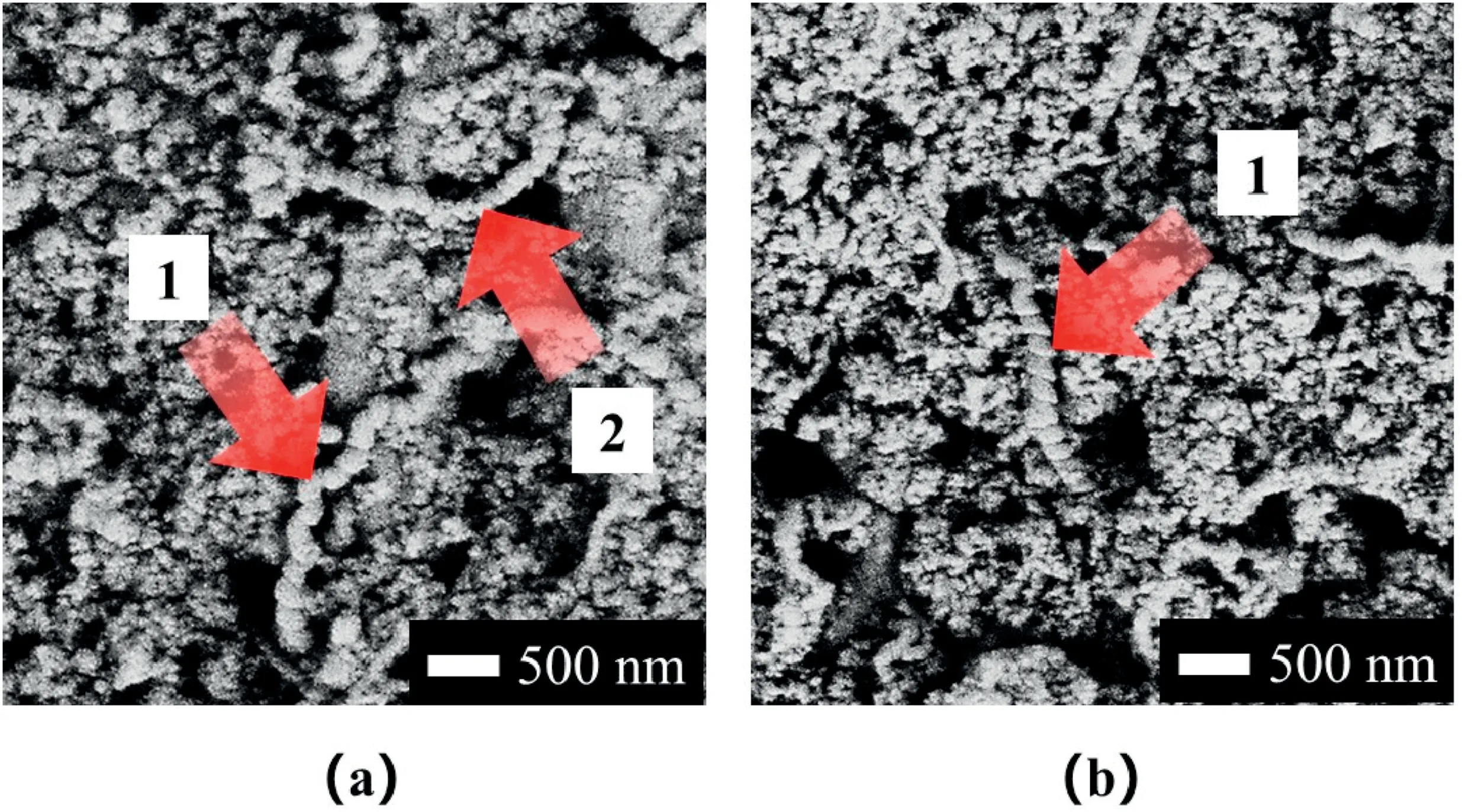
Fig.6.“Helical” CNTs on the Al-substrate of CHEM1,where “one” ends of CNTs in both (a) and (b) were pulled into the deep cavities (1) by the capillary action generated from the acetone evaporation process from the RPC solution.Some CNTs,e.g.one helical CNT in (a),remain the surface (2).
2.3.Capillary action and position of CNT “Z-pins” into micro-cavities on Al substrate
The CNT-containing resin pre-coating (RPC) solution is acetone rich(e.g.90 wt%acetone and 10 wt%resin)so that resin(without hardener)tends to fill in and remain within the surface and sub-surface microcavities after the complete acetone evaporation.This capillary actiondriven resin flow also takes CNTs into those micro-cavities.Fig.5 illustrates how CNTs are positioned into those vertical micro-channels or micro-cavities generated from anodising and sandblasting.Depending on the acetone/resin ratio,the RPC process can be repeated if necessary.Fig.6 shows“helical”CNT examples on the CHEM1 Al substrate surface of Fig.1,where “one” ends of some helical CNTs have been pulled into micro-cavities by the capillary action generated from the acetone evaporation process from the RPC solution.
It should be mentioned again that a perfect CNT dispersion is not necessary for typical adhesive bonding,and it is sufficient to perform simple mechanical stirring in the RPC solution for a few minutes.Then the CNT-containing RPC solution is ready to apply over the chemically or mechanically treated Al substrate surfaces as illustrated in Fig.5.After the complete evaporation of acetone,the normal epoxy adhesive(resin +hardener mixture) can be applied.There is no need to further mix CNT with the viscous epoxy adhesives.
3.Materials details and chemical surface treatments/characterisations
3.1.Chemical anodising of Al substrates and sandblasting of steel
The Al substrate samples (6065 T5) were anodised by similar procedures where the chemically alkaline etching was designed as the pretreatment,and electrochemically anodising was intended as the primary processing step.All major raw materials and their properties are listed in Table 1.
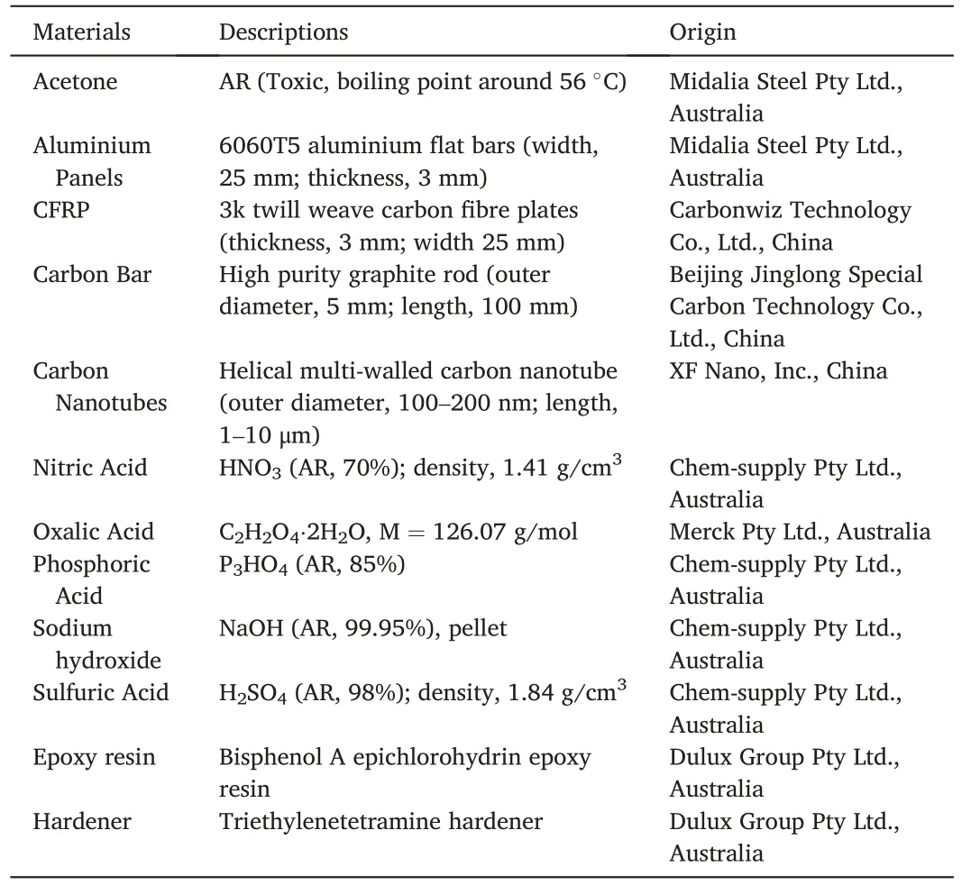
Table 1 Main raw materials and their properties.
Pre-treatments were necessary before the anodising treatment of Al substrates.Al alloy samples were ultrasonic cleaned in acetone for 30 min to remove any surface contaminants.Then they were put into a 10 wt%NaOH solution for 10 min to remove poorly soluble substrates.After etching by the NaOH solution,the Al samples were cleaned by deionised water.Then Al substrates were soaked into 10 wt% HNO3solution for 5 min to neutralise and remove NaOH residua.Anodising treatment on Al was designed to create surface structures.CHEM1 applied 20 wt% sulfuric acid dopted 0.5 wt% oxalic acid as the electrolyte while CHEM2 used 20 wt%phosphoric acid.Both CMEM 1&2 were treated under 12 V for 60 min.Different from Al,steel substrates (Fig.4) were sandblasted using GMA Premium Blast (Perth,Australia) garnet with a grit size of 30–60 μm at a compressed air pressure of 5 bar after pre-ultrasoniccleaned by acetone.
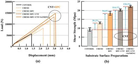
Fig.7.(a)The load and displacement curves of each group closest to the average of 6 tests(Al substrate with deep vertical micro-channels as in Fig.1).Besides the maximum shear load,the critical displacement and energy are also enhanced significantly for the CNT +RPC combinations.(b)The average shear strength from 6 SLS tests.The combinations of CNT +RPC (resin pre-coating) are the most effective.

Fig.8.Shear failure surfaces with different features linked to surface treatments.
All treated metal substrates were soaked in CNT-contained resin precoating solution(weight ratio of acetone to resin to CNT was 89:10:1)for 30 s.CNTs remained in micro-valleys after acetone was completely evaporated.All CNT-rich and resin pre-coated metals were designed to be adhesively bonded with CFRP.The adhesive mixing ratio (adhesive to hardener) was 1:1.When joints were cured at room temperature,they were stored in the oven (60°C) for 3 days,ensuring adhesive mixtures were cured completely.
3.2.Characterisation of samples
Instron 5982 universal testing machine,Instron Corp.,USA,was applied to test single-lap shear stresses of adhesively connected joints according to ASTM 5868 [22].The operational parameters were set to 100 kN tensile fixture,a steady rate of 1 mm/min,and automatically recorded every 0.1 s for load and crosshead displacement.
Morphologies and microstructure of pretreated aluminium and anodised aluminium were investigated using a scanning electron microscope(FEI Verios XHR SEM,Thermo Fisher Scientific Inc.,USA)by the Everhart-Thornley detector(ETD)at 20 kV/0.8 nA while 10 kV/0.4 nA for steel substrates.Internal pore feature was examined by focused ion beam(FIB,FEI Helios 650,Thermo Fisher Scientific Inc.,USA)with a high voltage of 5.0 kV and current of 0.34 nA.The Ga +beam with a depth of 30 μm was applied to cut and polish.
Contact angles with water droplets on both treated and untreated Al before PRC were measured by an OCA20 contact angle meter (Data-Physics Instruments GmbH,Germany)with a water drop size of 2 μL.
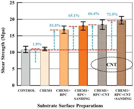
Fig.9.Shear strengths from 5 tests per group from samples made from CFRP and the Al substrate with relatively flat surface cavities as shown in Fig.2.CNT +RPC is still the most effective,but the increase of 73.5%is noticeably less than the 134.2% enhancement from the Al substrate with deep vertical microchannels in Fig.1.

Fig.10.Cross-section views of contact angles for “CONTROL” group,CHEM1 anodised Al (Fig.1) and CHEM2 anodised Al (Fig.2) before RPC.
Surface height profiles were evaluated by an Altisurf 520 profilometer(Altimet SAS,France).The CCS Prima confocal displacement sensor(CL3,Schmitt Industries,Inc.,Portland) was selected to set spot size,normal and lateral resolution as 4 μm,25 nm and 2 μm.An area of 2 mm× 2 mm in both x and y directions were detected.
4.Experimental results
4.1.Chemically treated Al substrates with CNT reinforcement applied by RPC
The single-lap shear (SLS) test samples of adhesive bonded Al and CFRP were prepared and tested from the two Al substrates with distinctly different surface profiles generated from two different chemical surface treatments,as shown in Figs.1 and 2.The test results are shown in Fig.7 and Fig.9,respectively.The adhesive joint thickness is 0.76 mm,and the adhesive-bonded area is 25.4 × 25.4 mm2.The Al plates have the measurements of 101.6 × 25.4 × 3 mm3and the CFRP plates have the dimensions of 101.6× 25.4× 2 mm3.
The “CONTROL” condition inFig.7(b) with the average shear strength of 9.6 MPa is for common adhesive bonding after acetone cleaning of both Al substrate and CFRP plate.“CHEM1”represents the Al substrate with vertical micro-channels,which is then bonded to CFRP normally.The average shear strength of 13.36 MPa is a 39.2% increase from the CONTROL condition.“CHEM1+RPC” with the average shear strength of 18.62 MPa for adhesive bonding after RPC(resin pre-coating)on both Al substrate and CFRP,i.e.the increase from 13.36 to 18.62 MPa(39.4% increase) is due purely to the effect of RPC.This shear strength increase implies that normal viscous epoxy adhesive cannot completely fill in the micro-channels of Al substrate shown in Fig.1.The last two groups in Fig.7(b)with average shear strengths of 20.55 and 22.48 MPa are results with the combination of CNT +RPC.CFRP of the last group was roughened slightly using#120 SiC sandpaper,followed by RPC.The largest 134.2%increase from the base CONTROL condition is significant.
The typical shear failure modes corresponding to the substrate conditions in Fig.7 are shown in Fig.8.CONTROL has a typical adhesive failure along with the interface between Al substrate and adhesive joint.CHEM1+RPC has a mixture of adhesive failures at the interfaces on the Al substrate and CFRP sides and some degree of cohesive failure.That is,because of RPC,the interface between the Al substrate and adhesive joint is no longer the dominant weakest link in the adhesive-bonded composite structure.With the CNT reinforcement (for the CHEM1+RPC+CNT condition),the primary failure mode is shifted towards the interface between CFRP and adhesive joint.Failure inside CFRP has occurred and is clearly visible in Fig.8.With RPC over CFRP after slight roughening by#120 SiC sandpaper,the CNT-reinforced adhesive joint and its two interfaces with both Al substrate and CFRP are so strong that failure could only occur inside the CFRP substrate through delamination or tearing failures of carbon fibres.
Shear strengths from samples made from CFRP and the Al substrate with relatively flat surface cavities in Fig.2 are shown in Fig.9.The CONTROL (only acetone cleaning) and CHEM2 (Al substrate with chemical treatment) have almost identical shear strengths,11.20 and 11.50 MPa,respectively.These similar shear strengths are probably as expected since both CONTROL and CHEM2 Al substrates have similar surface roughness,as can be seen from Fig.2(a)and(b).
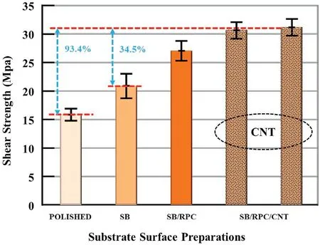
Fig.11.Epoxy adhesive-bonded steel substrates with 8 tests per group: Polished (using #120 SiC paper),SB (sandblasting),SB/RPC (SB +resin precoating),SB/RPC/CNT (SB +RPC +CNT,two separate tests with 8 samples per group).The highest enhancement from the CNT-PRC toughening is 93.4%from the polished surface,and is 34.5% from the sandblasted surface.
The CHEM2+RPC condition in Fig.9 shows the significant shear strength increase of 53.5% to 17.35 MPa,which confirms the ability of RPC to penetrate into those surface and sub-surface micro-cavities over the chemically treated Al substrate.The shear strength (CHEM2-+RPC+SAND) is increased further to 18.65 MPa (or 65.1%) by slight roughening of CFRP by #120 SiC sandpaper.The final two groups with CNT reinforcements show similar trends with average values of 18.80 and 19.60 MPa,respectively.The best result with 73.5%improvement is significantly less than 134.2% in Fig.7,proving the effectiveness of vertical micro-channels and CNT“Z-pins”across the Al substrate surface.
Contact angles for the CONTROL group,CHEM1 anodised Al,and CHEM2 anodised Al are described in Fig.10.Acetone ultrasonic cleaned Al substrates(CONTROL)witnesses a higher contact angle at 115°since contaminants still remained on Al's surface,leading to weak bonding strength between Al and adhesive.Sulfuric-oxalic acid anodised Al decreases contact angles to 68°since anodising treatment achieves increased wettability.Phosphoric acid anodised Al (CHEM2) has a slightly higher contact angle(78°)than sulfuric-oxalic acid anodised one(CHEM1).Low surface roughness contributes to this low wettability.
4.2.Sandblasted steel substrate with CNT reinforcement applied by RPC
For the purpose of comparison,the effects of CNT +RPC interfacial reinforcements on shear strengths of adhesive bonded mild steel substrates [16] are shown in Fig.11.Eight samples were tested for each group shown in Fig.11.The adhesive joint thickness is around 50 μm,and the adhesive-bonded area is 25×13 mm2.The mild steel plates have measurements of 40×25×3 mm3.
The shear strength between the two polished steel substrates (using#120 SiC paper) is 16.23 MPa and is 23.33 MPa for the sandblasted surface.RPC has further enhanced the shear strength to 28.18 MPa.Two separate tests(8 samples per group)with CNT-toughened adhesive joints produced the best and almost identical results of 31.07 and 31.39 MPa.Those results in Fig.11 for the steel substrate clearly show that normal adhesive bonding after sandblasting can still be improved by RPC +CNT,which is similar to the two Al substrate cases in Figs.7 and 9.A recent study [17] on adhesive bonding between CFRP and Al substrate with a sandblasting surface finish also shows that RPC alone can further enhance the shear strength by 35.1%.
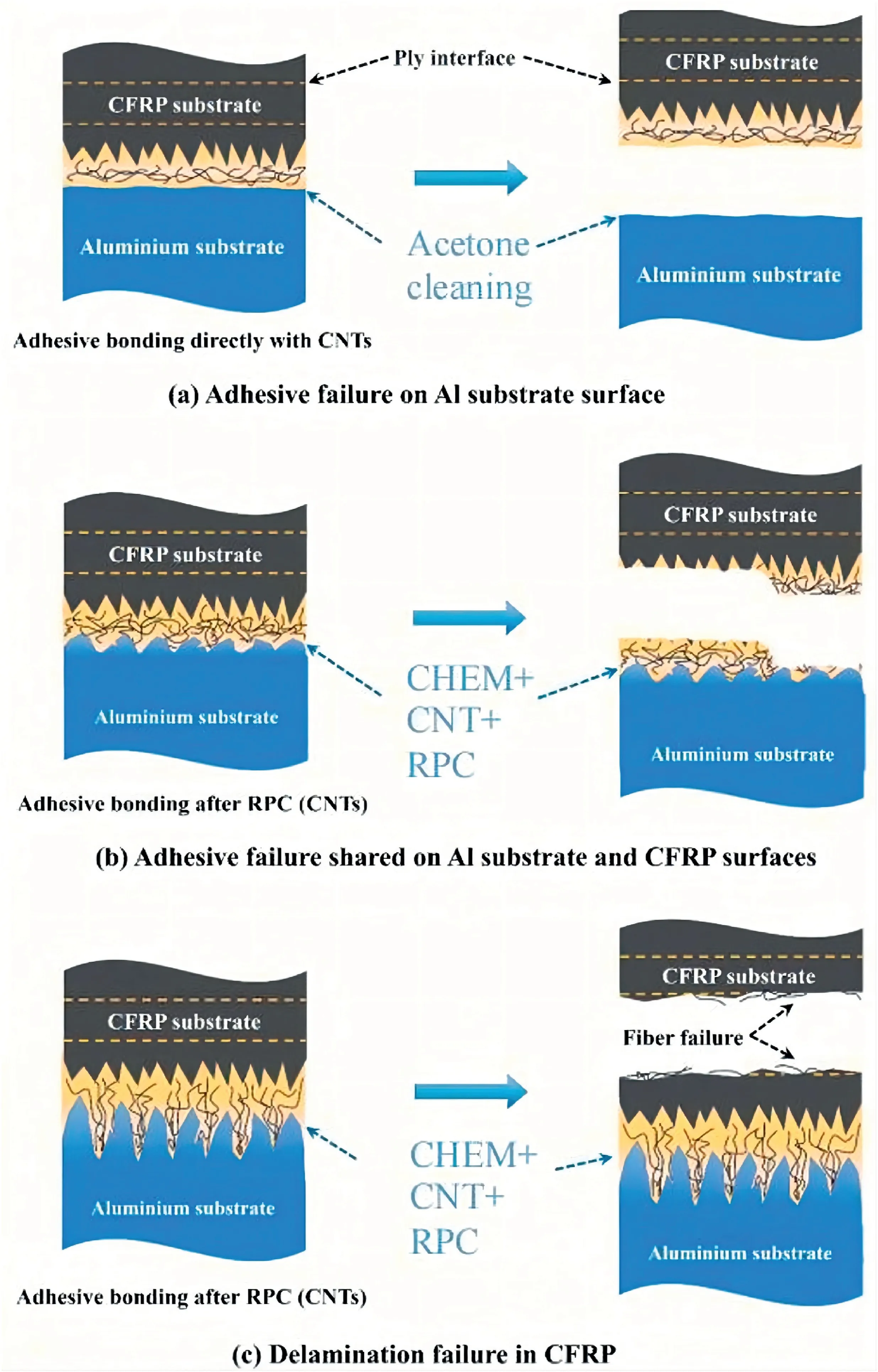
Fig.12.Three major failure modes of adhesive bonded Al and CFRP interface:(a)adhesive failure along the Al substrate surface,(b)cohesive failure in the adhesive joint (possibly with partial failure along CFRP surface),and (c) structural failure inside CFRP away from the CNT-toughened adhesive joint,which is possible if the adhesive joint is optimised and fully toughened.
5.Discussions
5.1.Effectiveness of CNT-toughening with RPC and relevant shear failure modes
The most considerable shear strength improvement is 134%,74%,and 93%for the three different substrate surfaces prepared chemically or mechanically.These results show that the CNT-containing RPC process is effective.Since CNT dispersion in the RPC solution is simple,and the CNT +RPC process can be conveniently used on-site and applied by engineers without special training and without the need for any special equipment,the unique interfacial toughening method proposed in this study has the potential to be adopted on-site for large-area adhesive bonding between Al substrate and CFRP.
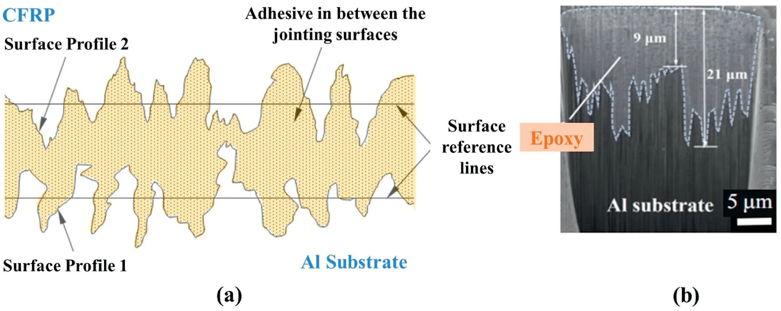
Fig.13.(a)Micro-roughness and cavities over Al and CFRP substrate surfaces[18],and(b)vertical micro-channels in Al substrate created by chemical treatment as in Fig.1(b).Resin pre-coating (RPC) has filled all micro-cavities,which may be difficult using normal epoxy adhesive due to relatively high viscosity.
The change or shift in the shear failure modes displayed in Fig.8 by the optical photos of test samples can be summarised by the illustrations in Fig.12.The commonly known two failure modes are:(1)the adhesive failure or failure along the interface between the substrate and adhesive joint,and(2)the cohesive failure or failure within the adhesive joint.The substrate surface treatments are designed to suppress adhesive failure.The CNT interfacial reinforcement can effectively prevent premature failures from either“the adhesive or cohesive mode”.
It is noticed that CNT +RPC can be so effective that neither adhesive nor cohesive failure is possible.In this case,the third failure mode,or(c)structural failure within CFRP,is generated.That is,the adhesive joint is no longer the weakest link in laminar Al-CFRP structures.This probably is the optimum adhesive bonding scenario,which can be expected for structural applications.
Besides establishing“Z-pins”by injecting CNTs into surface-modified metal interface structures,a similar setup by dispersing CNTs in epoxy matrix[23]can realise the same function of“Z-pins”.Functionalised CNT on matrix interface can connect to those micro-structures on adherend surfaces to realise “Z-pins” establishment.Adhesives strengthened by nanoparticles (e.g.,GNPs and CNTs [26,27]) can significantly improve the bulk strength of adhesive matrix and adhesive bond strength,up to the scale of 20–30 MPa.Again,CNT and micro-length or short fibres do not have to be vertical to strengthen the thin adhesive joint.The best content of CNT varies by surface roughness and micro-structures dimensions of adherents.Typically,optimum adhesive properties can be achieved with around 1–2 wt%CNTs[25].
5.2.RPC -optimisation of adhesive bonding area and strength
A comprehensive review of adhesive bonding between Al substrate and CFRP published recently[18] provides a good overview of the current technologies utilised for adhesive bonding of these two vastly different materials.The general illustration of Al and CFRP substrates[18] is shown in Fig.13(a),where micro-cavities exist on both Al and CFRP substrates.
While the “perfect” adhesive bonding condition along the surface profiles,as illustrated in Fig.13(a),is highly idealised,it has actually been achieved by the simple RPC method described in this study.The SEM-FIB micrograph in Fig.13(b) or part of Fig.1(b) shows the perfect adhesive bonding profile inside those vertical micro-channels created by the chemical surface treatment [15].The CNT “Z-pins” positioned into those vertical micro-channels by RPC provides the crack-bridging mechanism along the surface reference lines in Fig.13(a).It should also be mentioned that the RPC method adopted for the three adhesive bonding cases has also been tested on other substrates,including rock,wood and bamboo composites[19–21].
Last but not least,there is one more positive aspect of RPC,which is desirable for adhesive bonding.After filling and sealing all micro-and nano-pores (e.g.micro-porous structures shown in Fig.2 and TiO2nanotubes formed on the titanium alloy [24]),RPC also improves the wettability of the substrate.This is because the ultra-thin resin coating(without hardener) left over the substrate surface remain “wet” after evaporation of acetone.The comparison of the SEM micrographs of the steel surfaces shown in Fig.4(a)and(b)clearly shows the difference due to RPC.For the three types of surface profiles from CHEM1,CHEM2 and sandblasting,RPC is invariably effective.It is highly likely that RPC may also be useful even to the fine nanostructures reported in Ref.[24].
6.Conclusions
As summarised in Fig.13 and discussed in the review article[16],the thin adhesive joint between Al and CFRP substrates is typically un-reinforced,and micro-cavities exists on both substrates (that can be purposely prepared).This study compared two chemically treated Al substrates and one steel substrate prepared by sandblasting.The CFRP surface can be conveniently roughened by sandpapers if necessary.
This study examined the effectiveness of CNT-bridging across the thin adhesive joint between the Al and CFRP substrates.Filling of all microcavities over both substrate surfaces is ensured by the unique resin precoating (RPC) process,using the acetone-rich resin solution,e.g.acetone 90 wt% and resin 10 wt% (without hardener).CNTs are pulled into those micro-cavities and across the “surface reference lines” in Fig.13 by the capillary action generated by acetone evaporation so that CNT “Z-pins” or CNT-bridging across the thin adhesive joint becomes possible.Clearly,the effectiveness of CNT-bridging depends on the surface profiles of both Al and CFRP substrates.The highest shear bonding strength improvements for the three cases in this study are over 130%,70% and 90%,respectively,and they are all with CNT interfacial toughening.It can be concluded that the CNT-containing RPC solution has significantly improved the adhesive bond strength between the Al substrate and CFRP,and the method can be easily used on other substrates such as rock,concrete,wood and bamboo composites.
Declaration of competing interest
There are no conflicts to declare.
Acknowledgement
XZ Hu would like to thank Chang'an University of China for a visiting professor grant (2018-2020) for research collaboration between Chang'an University and University of Western Australia.
- Namo Materials Science的其它文章
- Fabrication of segregated poly(arylene sulfide sulfone)/graphene nanoplate composites reinforced by polymer fibers for electromagnetic interference shielding
- In situ polymerization preparation and mechanical properties of nanocomposites based on PA10T/10I-block-PEG copolymer and graphene oxide
- Abnormal enhancement to the quality factors of carbon nanotube via defects engineering
- Fracture behavior of hybrid epoxy nanocomposites based on multi-walled carbon nanotube and core-shell rubber
- Anti-corrosion and electrically conductive inorganic conversion coatings based on aligned graphene derivatives by electrodeposition
- Atomic insights into synergistic effect of pillared graphene by carbon nanotube on the mechanical properties of polymer nanocomposites

