
The phosphorescence nanocomposite thin film with rich oxygen vacancy: Towards sensitive oxygen sensor
2022-09-16 05:25JinYoJinKongLingweiKongXinruiWngWenyingShiChoLu
Chinese Chemical Letters 2022年8期
Jin Yo, Jin Kong, Lingwei Kong, Xinrui Wng, Wenying Shi,∗, Cho Lu
a State Key Laboratory of Chemical Resource Engineering, Beijing University of Chemical Technology, Beijing 100029, China
b Key Laboratory of Cosmetic, China National Light Industry, Beijing Technology and Business University, Beijing 100048, China
ABSTRACT Organic room temperature phosphorescent (ORTP) materials provide an exciting research direction for phosphorescent oxygen (O2) sensors due to their high sensitivity and rapid response to O2.However,most pure ORTP materials are tightly-packed aromatic compound crystals in a face-to-face manner, which largely prohibits effective O2 diffusion for sensing.Thus, how to solve this contradiction still faces huge challenges.Here, the use of organic phosphorescent indicator carbon dots (CDs), inorganic matrix layered double hydroxides (LDHs) and polymers (PVA) successfully prepared an ultra-long RTP composite film whose phosphorescence decay intensity is linearly related to O2 concentration.More importantly, the use of the abundant O2 defects (Vo) on the surface of the inorganic matrix LDHs to adsorb O2, which further accelerates the phosphorescence quenching of the thin film and improves the O2 response.This strategy will provide the possibility to develop high-sensitivity phosphorescent O2 sensors from a new perspective.
Keywords:Layered double hydroxides Carbon dots Nanocomposite thin film Phosphorescence Oxygen vacancy Oxygen-sensing
The determination of oxygen (O2) concentration undoubtedly is still a leading priority for many applications [1–4].Optical O2sensor is one of the areas that is accelerating the fastest over the past two decades, and proved to be indispensable technologies for O2quantification which have mostly replaced the more conventional Clark electrode [5,6].Especially, it should be pointed out that electronic ground state of O2is a spin triplet, thus, phosphorescent material with triplet excitons are the most suitable candidates as O2sensor [7–11].Despite the tremendous efforts have been devoted to the design of novel high-performance phosphorescent O2sensors, a reliable, long operational lifetime, fast response, and organic room temperature phosphorescent (ORTP) O2sensor represents a formidable challenge.This is due to the inherent shortcomings of ORTP materials where the triplet excitons commonly wasted by radiation-free relaxation processes such as heat energy and mobilized energy owing to spin symmetry different from the ground state [12–14].Therefore, an effective way to break the current bottleneck is to find a suitable ORTP material.
Generally, in term of obtaining pure ORTP materials, crystal engineering is the most widely employed method.However, because most ORTP materials tightly-packed aromatic compound crystals in a face-to-face manner through strong intermolecularπ-πinteractions, effective O2diffusion for sensing is largely prohibited [15–17].Therefore, achieving purely organic ultra-long RTP and allowing excellent O2diffusion for O2sensing seem to be contradictory[18].Based on these problems, the development of RTP materials based on organic-inorganic doping is an excellent choice.Both the nature of the organic phosphorescent indicator and the inorganic matrix are of vital importance since the sensitivity of an O2sensor is roughly proportional to the phosphorescent decay intensity of the indicator and to the O2permeability of the matrix [19].
To validate our hypothesis, carbon dots (CDs) and layered double hydroxides (LDHs) were chosen as the organic phosphorescent indicator and inorganic matrix, respectively.The former is a new organic light-emitting material, can achieve long-life RTP by doping into matrices (polymer [20], steroid analogue [21], micelles[22], cavity of cyclodextrin [23] or inorganic crystals [24]).The latter can not only inhibit the radiation-free relaxation process of triplet excitons, but as rigid matrix also have rich surface O2defects (Vo) which is beneficial to capturing of O2[25,26].Therefore, we tried to design a phosphorescence composite film system based on CDs, LDHs and polymer (PVA) to explore the phosphorescent O2sensor [27–29].The resultant materials show the prepared(Zn-CDs-LDHs/PVA)40composite film has an ultra-long RTP life of about 1 s.The phosphorescence decay intensity of this film is linearly related to the O2concentration.Importantly, increased Vo of LDHs promoted O2adsorption, accompany with accelerated phosphorescence quenching and improved O2response.
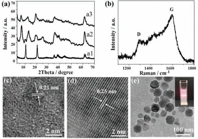
Fig.1.(a) XRD patterns of (a1) LDHs-NO3, (a2) EDTA-LDHs and (a3) Zn-CDs-LDHs.(b) Raman spectra, (c, d) HRTEM image and (e) TEM image (inset: digital photograph of its colloidal suspension) for Zn-CDs-LDHs.
Firstly, Zn-CDs-LDHs was proved to be formed.The intercalation of EDTA into the LDHs gallery was confirmed by XRD, where the XRD pattern of EDTA-LDHs has a significant shift in diffraction peaks from 2θ=10.27° to 6.87° compared with LDHs-NO3(Fig.1a).Then, EDTA-LDHs and Zn(NO3)2salt aqueous solution are mixed and stirred to make complexation reaction between Zn2+and EDTA.After hydrothermal treatment at 250 °C, the formation of CDs can be testified by appearance the D bands ascribed to sp3defects and G bands related to sp2-bonded C atoms at approximately 1302 and 1600 cm–1, respectively (Fig.1b).Importantly, Zn-CDs-LDHs still remain the characteristic diffraction of the LDHs layer structure with a further shift to 2θ=6.52° Fig.1c shows the HRTEM image of Zn-CDs-LDHs has the lattice fringe of 0.21 nm attributed to the(100) facet of graphite [30], which further proves the formation of Zn-CDs in interlayer of LDHs.The HRTEM image of Zn-CDs-LDHs also shows the lattice fringe of 0.25 nm attributed to the (012) of LDHs (Fig.1d) [31].The TEM image of Zn-CDs-LDHs shows that the hexagonal plate-like morphology is also kept after hydrothermal treatment (Fig.1e).These results disclose that hydrothermal treatment does not destroy the structure and morphology of LDHs.The digital photograph shows the obvious Tyndall phenomenon, illustrating a stable colloidal suspension (inset in Fig.1e).
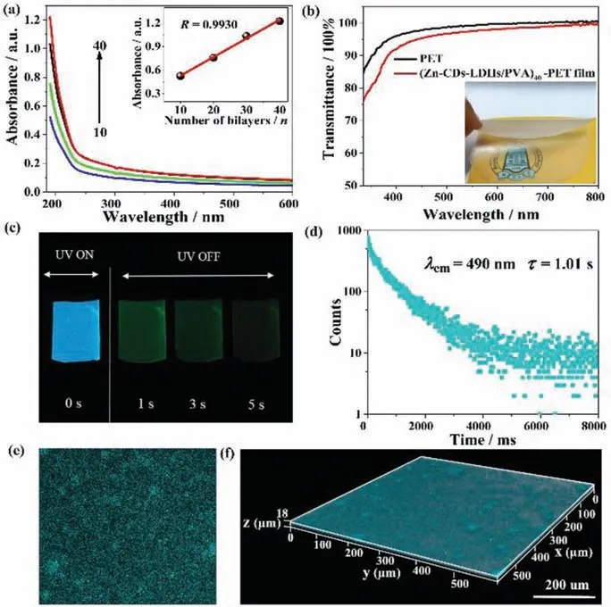
Fig.2.(a) UV–vis absorption spectra of (Zn-CDs-LDHs/PVA)n (n = 10, 20, 30 and 40) film on quartz glass substrate (inset: the linear relationship between the absorbance at 190 nm and the bilayer number n).(b) UV–vis transmittance spectra(inset: photograph of the (Zn-CDs-LDHs/PVA)40 film).(c) Fluorescence and phosphorescence photographs of the (Zn-CDs-LDHs/PVA)40 film taken at different time intervals before and after turning off the UV excitation (365 nm).(d) Time-resolved phosphorescence spectra, (e) 2D fluorescence and (f) 3D fluorescence image of the(Zn-CDs-LDHs/PVA)40 film.
The assembly process of (Zn-CDs-LDHs/PVA)nfilm was monitored by UV–vis absorption shown in Fig.2a.The characteristic absorption of PVA at 190 nm enhances linearly with the increase of bilayer numbersn, indicating a stepwise and regular deposition process for (Zn-CDs-LDHs/PVA)nfilm (inset in Fig.2a).This conclusion can be further confirmed by similar phenomenon of the phosphorescence spectra (Fig.S1 in Supporting information).Moreover,the hydrogen bonds between LDHs and PVA has been confirmed by FTIR and XPS (Fig.S2 in Supporting information).SAXS pattern shows an obvious small angle diffraction peak at 2θ=0.93°, indicating the (Zn-CDs-LDHs/PVA)40film has an ordered superlattice structure in theZdirection (Fig.S3 in Supporting information).The orientation of the Zn-CDs-LDHs nanosheets in the film was verified by XRD (Fig.S4 in Supporting information).The top-view and side-view SEM images of the (Zn-CDs-LDHs/PVA)40film exhibit a smooth and continuous surface with a thickness of ∼1.97 μm(Figs.S5 and S6 in Supporting information).The AFM topographical image shows the root-mean-square (rms) roughness value of(Zn-CDs-LDHs/PVA)n(n= 10, 20, 30 and 40) film increases from 5.5 nm to 23.9 nm with the increase of bilayer numbersn(Fig.S7 in Supporting information).This also shows that the film possesses a homogeneous and smooth surface.The orientation and arrangement of Zn-CDs-LDHs in (Zn-CDs-LDHs/PVA)nfilm can be obtained by using the polarized fluorescence method due to the introduction of CDs as chromophore.The fluorescence anisotropic value(r) is determined by two typical measurement setups of polarized fluorescence, including the glancing and normal incidence geometries [32].Theris 0.25 of the (Zn-CDs-LDHs/PVA)40film by spin coating method (Fig.S8 in Supporting information).In contrast,theris only 0.025 of the film by the solvent evaporation method.Thus, we chose the spin coating method as the assembly method.In addition, the (Zn-CDs-LDHs/PVA)40film exhibits high flexibility and remarkable transparency with a light transmittance over 90% across the visible-light spectrum from 400 nm to 800 nm (Fig.2b).The well- dispersed and oriented Zn-CDs-LDHs nanoplatelets within PVA matrix account for this high level of transparency.Fig.2c shows the (Zn-CDs-LDHs/PVA)40film emits blue light under ultraviolet light (365 nm).Interestingly, after removing the UV light,the film emits green phosphorescence and tardily fades with a remarkably long time of 5 s at room temperature.The luminescence spectrum show phosphorescence emission peak at 490 nm and the fluorescence emission peak at 385 nm (Figs.S9 and S10 in Supporting information).It should be noted that the effect of scattered light (Rayleigh and Raman scattered light) have been excluded (Fig.S11 in Supporting information).The average fluorescence and phosphorescence lifetime of the (Zn-CDs-LDHs/PVA)40film is 1.6 ns (Fig.S12 and Table S1 in Supporting information), and 1.01 s in the atmosphere (Fig.2d and Table S2 in Supporting information), respectively.The ultra-long room temperature phosphorescence lifetime provides the possibility for O2sensing and even naked eye observation.
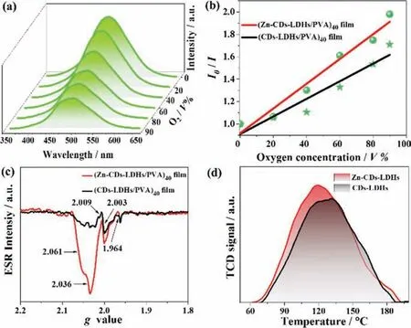
Fig.3.(a) The phosphorescence emission spectra of the (Zn-CDs-LDHs/PVA)40 film under different O2 concentrations.(b) Plots of I0/I1 for the (Zn-CDs-LDHs/PVA)40 and (CDs-LDHs/PVA)40 film as a function of O2 concentration.(c) ESR of the (Zn-CDs-LDHs/PVA)40 and the (CDs-LDHs/PVA)40 film.(d) O2 TPD profiles of Zn-CDs-LDHs and CDs-LDHs powder.
Due to the introduction of CDs, the distribution of Zn-CDs-LDH nanoparticle in the composite film can be monitored from a macroscopic scale by fluorescence confocal microscope.As shown in Fig.2e, the dark background of the two-dimensional (2D) confocal microscope image is filled with countless fluorescent particles to offer a fluorescence distribution map.The macroscopic uniform distribution of Zn-CDs-LDHs in PVA can be proved.This can also be proved by the 3D image, because three-dimensional (3D) fluorescence image in theXYplane was collected at different depths usingZ-scan technique (Fig.2f).Noting that the overall dispersion is relatively uniform, except for a small part of the aggregation.The 3D image more realistically reflects the distribution of Zn-CDs-LDHs from a larger area, promoting a fair judgment of the overall dispersion of the (Zn-CDs-LDHs/PVA)40film.
Because electronic ground state of O2is a spin triplet, which can quench long-lived triplet phosphorescence by energy transfer to the lowest singlet state [33].The as-prepared film has a dependence of phosphorescence intensity on O2concentration.Therefore, we studied the phosphorescence intensity change of the film under different O2ratio conditions.The phosphorescence intensities of the (Zn-CDs-LDHs/PVA)40film (Fig.3a) and the (CDs-LDHs/PVA)40film (Fig.S13 in Supporting information) decreases with the increase of O2concentration.The schematic diagram of the experimental device is shown in Fig.S14 (Supporting information).More intuitively, the relationship of phosphorescence intensity with O2concentration is expressed by the Stern–Volmer quenching Eq.1 [34]:

in whichI0andIrepresent the phosphorescence intensity under pure N2atmosphere and a certain partial pressure of O2,and [O2] is the O2volume concentration.Ksvis the Stern–Volmer quenching constant.Fig.3b shows the linear equations of the phosphorescence intensity of (Zn-CDs-LDHs/PVA)40and the (CDs-LDHs/PVA)40film in response to different O2concentrations.The slopes of the (Zn-CDs-LDHs/PVA)40and the (CDs-LDHs/PVA)40film areKsv=0.011 andKsv=0.007, respectively.This indicates that these films can be used as O2responsive phosphorescent sensors.Obviously, the comparison results show the (Zn-CDs-LDHs/PVA)40film has a higherKsv, indicating more sensitive and responds faster to O2.This phenomenon shows that the appearance of Zn2+plays an important role in accelerating phosphorescence quenching.The interesting phenomenon will be discussed in detail in the next section.In order to eliminate the dissociation of triplet excitons caused by Vo, the phosphorescence intensities of the corresponding films in nitrogen under the same conditions are compared.As is shown in Fig.S15 (Supporting information), the phosphorescence intensity of (Zn-CDs-LDHs/PVA)40film with more Vo is significantly higher than that of (CDs-LDHs/PVA)40film.This indicates that more Vo do not lead to the dissociation of triplet excitons and reduces the phosphorescence intensity of the films.
Considering that Zn, as a co-dopant or trigger, can induce the formation of defects under environmental conditions [35].Therefore, it is speculated that the Vo of LDHs may serve as O2trap centers and accelerate the phosphorescence quenching of Zn-CDs.In order to verify this conclusion, by combining Electron spin resonance (ESR), positron annihilation lifetime spectroscopy (PALS),and O2temperature programmed desorption (TPD), the defect type, concentration, and ability to store O2were systematically studied.ESR is an important tool for studying unpaired electronic states in compounds, impurities and defects in semiconductors.Therefore, ESR spectroscopy can be used as an effective technique to probe the type of trap centers (defects) in the (Zn-CDs-LDHs/PVA)40film.As is shown in Fig.3c, the (Zn-CDs-LDHs/PVA)40film show multiple signals withg= 1.964, 2.003, 2.009, 2.036 and 2.061.ESR signal atg= 1.964 is attributed to shallow donors in the bulk or at the surface region [36].The signalg= 2.003 could be identified as an electron trapped around Vo [37].It should be noted that there are three signalg= 2.061,g= 2.036 andg=2.009 are attributed to the charged oxygen species.However, first signal is attributed to the surface adsorbed O2–ion [38], and two latter are attributed to another type of O2–ion.This is similar to previous report in study on ZnZSM-5 catalyst reported by Denget al.[39].This is due to that, in the crystal field, the differentgvalue indicates different orbital energy difference.A smallergvalue corresponds to a larger orbital energy difference [40].As a comparison, ESR of the (CDs-LDHs/PVA)40film also was tested.The similar signals were observed, but the intensity of signals (g= 2.003,2.036 and 2.061) decreased to some extent.This result illustrates the introduction of Zn2+can increase the concentration of Vo, but no effect on the type of defects from LDHs host material.
In order to prove that the introduction of Zn2+increase the total Vo concentration, the PALS method was used [41].Table 1 shows the (Zn-CDs-LDHs/PVA)40and the (CDs-LDHs/PVA)40film have three positron lifetimes (τ1,τ2,τ3).Theτ1attributed to bulk defects.Theτ2assigned to Vo clusters which is usually formed on the surface and interface of nanoparticles.Theτ3is generally attributed to the annihilation of ortho-positronium (o-Ps) atoms formed in large pores inside the material.The ratio of surface to bulk defect (I2/I1) is in direct proportion to the concentration of Vo.TheI2/I1for the (Zn-CDs-LDHs/PVA)40film and the (CDs-LDHs/PVA)40film are 0.424± 0.002 and 0.348± 0.001, respectively.The higherI2/I1for the (Zn-CDs-LDHs/PVA)40film, indicating that the introduction of Zn2+increases total Vo concentration.The similar phenomenon has been reported by previous work in study Zndoped TiO2nanoparticles for photophysical and photocatalytic processes [42].

Table 1 Positron lifetime parameters of the samples.
To further demonstrate that Vo can be combined with O2.O2TPD, which is an important technique for studying the interaction between surface active centers and adsorbed molecules,was performed to detect the binding capacity Zn-CDs-LDHs to O2molecules.Fig.3d shows the Zn-CDs-LDHs has a desorption peak located at 120.6 °C, indicating that a strong chemisorption interaction between O2molecules and Zn-CDs-LDHs.The controlled CDs-LDHs displays a desorption peak located at 126 °C.The stronger desorption peak and the larger integral area of Zn-CDs-LDHs, indicating that Zn-CDs-LDHs contains more Vo and has a stronger desorption strength for O2.Therefore, the introduction of Zn2+in-creases the number of Vo, resulting in excellent O2storage capacity.The adsorbed O2further accelerates the quenching of the phosphorescence of the Zn-CDs-LDHs.In summary, the Vo of LDHs can be adjusted to improve the phosphorescence O2response of the phosphorescence composite film.
In addition, flexible optical films often face different humidity environment in practical applications, and water molecules will cause their optical signals to decrease [43].As shown in Fig.S16 (Supporting information), the phosphorescence intensity of the(Zn-CDs-LDHs/PVA)40film decreases as the relative humidity (RH)increases.The schematic diagram of the optical test of the film in different humidity experiment was shown in Fig.S17 (Supporting information).A cycle test shows the phosphorescence can reversible responses between 33% RH and 98% RH.Almost 88% of the original phosphorescence intensity could be recovered, implying that the (Zn-CDs-LDHs/PVA)40film could potentially serve as a humidity-response phosphorescence sensor (Fig.S18 in Supporting information).The thermal stability and storage stability was also further studied.Thermogravimetric analysis shows the weight of the (Zn-CDs-LDHs/PVA)40film does not show obvious loss until the temperature increases to 400 °C (Fig.S19 in Supporting information), indicating the superior thermal stability.The storage stability test shows the phosphorescence intensity of the (Zn-CDs-LDHs/PVA)40film can be maintained at around 70% after one month (Fig.S20 in Supporting information), which illustrates that the availability of as-prepared film for practical applications.
In summary, we propose a universal method to improve the O2response of phosphorescent films, avoiding the contradiction between achieving organic ultra-long RTP and allowing excellent O2diffusion.In our proposed protocol, the confinement effect of the inorganic matrix LDHs inhibits the radiation-free relaxation process of the triplet excitons of the CDs, resulting in the achieving of long-lived RTP.More importantly, using Vo on the LDHs surface promotes O2adsorption, accompanied by accelerated phosphorescence quenching and improved O2response.We affirm that our system definitely is not a particular event.This should be an important step to further develop and improve the O2response of phosphorescent films.This strategy is expected to expand the range of RTP candidates and bring more possibilities for RTP in various fields, such as high-efficiency displays and optoelectronic devices.
Declaration of competing interest
The authors declare that they have no known competing financial interests or personal relationships that could have appeared to influence the work reported in this paper.
Acknowledgments
This work was supported by the National Key R&D Program of China (No.2019YFC1906100), the National Natural Science Foundation of China (Nos.22171018, 21571014 and 21521005), the Beijing Municipal Natural Science Foundation (No.2172044), the Open Research Fund Program of Key Laboratory of Cosmetic, China National Light Industry, Beijing Technology and Business University(No.KLC-2019-ZD1), and the Fundamental Research Funds for the Central Universities (No.12060093063).
Supplementary materials
Supplementary material associated with this article can be found, in the online version, at doi:10.1016/j.cclet.2021.11.003.
 Chinese Chemical Letters2022年8期
- Chinese Chemical Letters的其它文章
- Adsorptive removal of PPCPs from aqueous solution using carbon-based composites: A review
- A review on hollow fiber membrane module towards high separation efficiency: Process modeling in fouling perspective
- Recent advances in DNA glycosylase assays
- Chiral pillar[n]arenes: Conformation inversion, material preparation and applications
- Recent progress in carbon-based materials boosting electrochemical water splitting
- Working principle and application of photocatalytic optical fibers for the degradation and conversion of gaseous pollutants