
Dendrite-free and anti-corrosion Zn metal anode enabled by an artificial layer for high-performance Zn ion capacitor
2022-09-16 05:24ZhuoLiZheGongXioyuWuKeYeJunYnGuilingWngYingjinWeiKiZhuJinYiDinxueCoGuohuChen
Chinese Chemical Letters 2022年8期
Zhuo Li, Zhe Gong, Xioyu Wu, Ke Ye, Jun Yn, Guiling Wng, Yingjin Wei,Ki Zhu,, Jin Yi, Dinxue Co, Guohu Chen
a College of Materials Science and Chemical Engineering, Harbin Engineering University, Harbin 150001, China
b Department of Mechanical Engineering, Research Institute for Smart Energy, The Hong Kong Polytechnic University, Hong Kong, China
c Key Laboratory of Physics and Technology for Advanced Batteries (Ministry of Education), College of Physics, Jilin University, Changchun 130012, China
d Institute for Sustainable Energy/College of Sciences, Shanghai University, Shanghai 200444, China
ABSTRACT Aqueous zinc energy storage devices, holding various merits such as high specific capacity and low costs,have attracted extensive attention in recent years.Nevertheless, Zn metal anodes still suffer from a short lifespan and low Coulombic efficiency due to corrosion and side reactions in aqueous electrolytes.In this paper, we construct an artificial Sn inorganic layer on Zn metal anode through a facile strategy of atom exchange.The Sn layer suppresses Zn dendrite growth by facilitating homogeneous Zn plating and stripping during charge and discharge processes.Meanwhile, the Sn protective layer also serves as a physical barrier to decrease Zn corrosion and hydrogen generation.As a result, The Sn-coated anode (Sn|Zn) exhibits a low polarization voltage (∼34 mV at 0.5 mAh/cm2) after 800 testing hours and displays a smooth and an even surface without corrosion.Moreover, the zinc ion capacitor (Sn|Zn||activated carbon) is assembled with an enhanced capacity of 42 mAh/g and a capacity retention of 95% after 10,000 cycles at 5 A/g.This work demonstrates a feasible approach for the commercialization of aqueous Zn-based energy storage devices.
Keywords:Zn ion capacitor Aqueous electrolyte Surface structure Sn metal layer Anti-corrosion
Rechargeable lithium-ion batteries (LIBs) have been commercialized for decades meeting the demands for portable devices and electric vehicles.However, the issues concerning the low safety derived from the flammable organic electrolyte, spiky metal dendrite and the high cost of Li salts hinder the application of LIBs for large-scale grid energy storage systems [1–5].As one of the multivalent ion batteries, rechargeable aqueous zinc-ion batteries (ZIBs)attract massive attention owing to their inherent merits of high safety technology for energy storage and conversion, high specific energy density (820 mAh/g and 5850 mAh/cm3), low redox reaction potential (−0.76 Vvs.SHE.), non-flammable property, low cost,and environmental benign [6–8].Consequently, ZIBs are considered as one of the most promising alternative candidates for LIBs [9].Researchers world-wide have made great efforts on investigating proper cathode materials and stable electrolytes or electrolyte additives.However, the work on Zn metal anode requires more investigations.Specifically, Zn anode suffers from severe corrosion and dendrite formation during redox cycling, resulting in passivation and internal short circuit ultimately [1,10,11].Upon battery charging (Zn2+reduction on the anode) [12–14], hydrogen evolution reaction (HER) may occur on the interface between metal anode and electrolyte simultaneously [15], accompanying the locally increased pH value and the growth of insulating by-products loosely deposited on the surface of Zn anode.The passivation layer formation also consumes Zn ions in the electrolyte, leading to capacity decrease within a short time [16–20].Therefore, it calls for the practical and facile solutions to stabilize the Zn anode surface and hamper passivation [21–23].
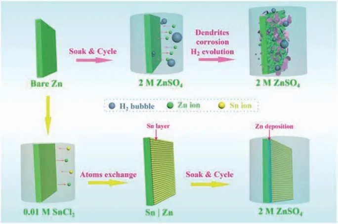
Fig.1.Schematics of the preparation of Sn layer on Zn anode and Zn deposition behaviors on the surface of bare Zn and Sn|Zn anodes.
Design and construction of a chemically stable and mechanically durable protective layer on the electrode is considered an effective way to suppress the dendrite growth and improve battery stability [24].In general, there are two main types of materials utilized to achieve surface modification: organic layer and inorganic layer [25].The organic layer could suppress the side reaction and promote the uniform Zn ion transport [26].Caoet al.applied commercial cyanoacrylate adhesive to zinc metal anode and achieved a high Coulombic efficiency of 99.74% [27].Zouet al.adhered konjac glucomannan on to Zn anode surface, the cycling performance and anti-corrosion ability were enhanced [28].Recently, the inorganic protected layer is developed to optimize the Zn electrodeposition and prevent the dendrite growth [29], such as coating Zn anode with CaCO3[30], TiO2[31] and 3D ZnO [32].A thin inorganic coating layer can facilitate the electrochemical reaction on the surface of the electrode [33], resulting in favourable electrochemical performance [34].Meanwhile, it hampers aqueous electrolyte infiltration into the surface of the electrode [35], consequently restrains hydrogen evolution reaction and contributes to compact deposition of Zn.Although the organic and inorganic layer modification strategies have shown exciting results [36,37], the complicated and time-consuming fabrication processes hinder their potential application, not to mention the unsatisfactory interfacial properties in the electrolyte/protective layer and protective layer/Zn anode.
Aqueous Zn ion capacitor (ZIC) has been considered as one of the most promising energy storage devices with capable power density for industrial application.With the advancement of smart wearable electronics, ZICs that possess flexible and non-toxic properties attract wide attention [38].Herein, we developed a smooth artificial protective film, Sn layer, on the surface of Zn anodeviaan extremely facile atom exchange strategy.The polished bare Zn foil was immersed in 0.01 mol/L SnCl2solution for 120 s, and then a durable Sn coated Zn (Sn|Zn) electrode was developed.The neatly and regularly arranged Sn particles on the Zn surface facilitated the distribution of charge and acted as artificial protective layer,inducing an even plating of Zn.In addition, the dense and protective Sn layer hindered HER and corrosion during the Zn plating and stripping process.In the symmetric cells with Sn|Zn electrodes, the excellent conductive Sn metal protective film results in a significantly low overpotential (<10 mV), ∼100% Coulombic efficiency(CE), and stable cycling performance (over 800 h).Moreover, a ZIC is designed and assembled with Sn|Zn anode and activated carbon(AC) cathode.The ZIC presents a high capacity of 42 mAh/g with a capacity retention of 95% after 10,000 cycles, demonstrating the potential application of Sn|Zn.
The preparation process of Sn coated Zn (Sn|Zn) is shown in Fig.1.Bare Zn foil was immersed in the SnCl2solution for 120 s and then the Sn layer was coated on the Zn electrode through a facile atom-exchange strategy with the mechanism given in Eq.1:

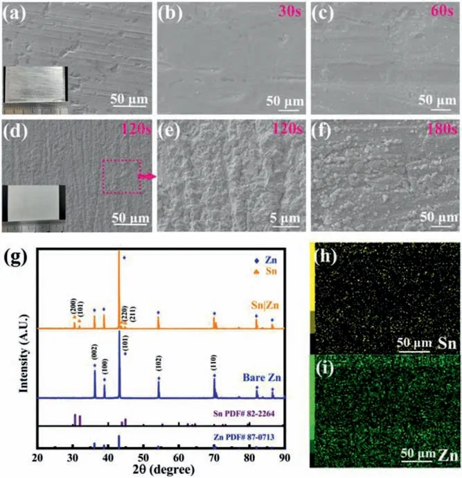
Fig.2.(a) SEM image of polished Zn foil.Morphology of immersing time for (b)30 s (c) 60 s (d) 120 s and (f) 180 s in 0.01 mol/L SnCl2 solution.(e) Magnified region of image (d).(g) X-ray diffraction patterns of bare Zn and Sn|Zn foil.(h, i)EDX elemental mapping of Sn|Zn foil.
The Sn layer can serve as an artificial SEI film to induce uniform Zn ion deposition, avoiding the irregular Zn dendrites growth [45].Meanwhile, the protective layer may suppress the hydrogen evolution reaction and by-product formation, leading to enhanced cycling stability of Zn anode.The original zinc metal foil and polished zinc foil were shiny and silvery (Fig.2a and Fig.S2 in Supporting information).After coating with the Sn layer, the electrode lost the metallic lustre.To better understand the most suitable time for an even morphology of Sn layer, SEM images were obtained.Figs.2b-d and f display the surface morphology of Zn foils after being immersed in 0.01 mol/L SnCl2solutions for 30 s, 60 s, 120 s and 180 s, respectively.As shown in Fig.2b, there are few particles on the Zn surface.With increasing reaction time to 60 s, some particles are observed as shown in Fig.2c, suggesting a fact that rendering the process 60 s or less is not enough for an even Sn layer formation.Figs.2d and f display that the Zn foil is covered with particles arranged continuously with superior order, demonstrating Sn layer is generated on the Zn foil when the reaction time was over 120 s.Prolonged atom exchange results in the formation of plenty of particles with the size of 2–10 μm and some fissures on the Zn foils.The visual inspection shows that 120 s atom exchange gives the most suitable Sn coating on Zn.Further magnification of the samples with 120 s reaction show more details about the surface that has been fully covered by Sn (Fig.2e).There are multiple clusters on the surface of Zn immersed for 180 s which indicates a worse morphology than that of 120 s (Fig.2f).Fig.2g presents the XRD spectra of Sn|Zn and bare Zn foils.The dominant peaks at 36.29°, 38.99° and 43.22° correspond to plane (002),(100) and (101) of standard Zn (JCPDS No.87–0813), respectively[46].The presence of peaks at 30.64°, 32.02°, 43.88° and 44.90°coincides with the crystal plane (200), (101), (220) and (211) of Sn,respectively, indicating the existence of Sn on Zn foil.EDX elemental mappings (Figs.2h and i) show that Sn is uniformly distributed on Zn substrate.
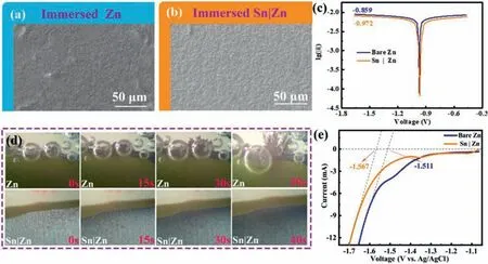
Fig.3.SEM images of (a) polished Zn foil and (b) Sn|Zn immersed in 2 mol/L ZnSO4 solution for 14 days.(c) Corrosion curves of polished Zn and Sn|Zn anode in 2 mol/L ZnSO4 solution.(d) Optical microscopy images of polished Zn (up) and Sn|Zn (down) in 2 mol/L ZnSO4 electrolyte at 20 mA/cm2.(e) LSV curves of bare Zn and Sn|Zn in a 1 mol/L Na2SO4 solution at a scan rate of 5 mV/s.
To examine the effect of the Sn layer on Zn corrosion resistance,Sn|Zn and bare Zn foils were immersed in the static 2 mol/L ZnSO4electrolyte synchronously for 14 days.SEM image (Fig.3a) shows countless flakes on the surface of bare Zn foil, which is attributed to the by-products originated from the reaction between OH−ions and the surface of Zn foil, which is loose and random.Meanwhile,there are many corrosion voids and vertical flaky by-products on Zn foil (Fig.S3 in Supporting information).In contrast, the surface of Sn|Zn foil changes insignificantly, suggesting its stability in aqueous electrolyte (Fig.3b).Fig.3c presents the corrosion curves of bare Zn and Sn|Zn foils.Linear polarization analysis was used to determine the current density of corrosion, which reflects the protective performance of the Sn layer.The corrosion current density of Sn coated Zn is lower than that of Zn foil, demonstrating the anti-corrosive quality of Sn|Zn [47].The enhanced anti-corrosive ability is ascribed to the Sn layer, which serves as a physical barrier to reduce the contact between Zn foil and water [48].In addition, the dendrite-growth was monitored through an optical microscope.The tiny symmetric cell consisted of 1 mL 2 mol/L ZnSO4electrolyte, Sn|Zn or Zn electrode, which was 2 mm in width.As shown in Fig.3d, for the Zn foil, H2gas bubbles are generated on the surface of Zn after only 5 s, and the dendrite sprouts out at the same time.About 30 s later, snow flake-like dendrites become sharp and large rapidly, and the volumes of the bubbles are also comparatively larger.Eventually, the dendrites connect to another electrode, causing a short circuit [49].In contrast, there are almost no conspicuous dendrites and corrosion on the surface of Sn|Zn anode.It is clear that the colour of the electrode surface turns from bright to grey homogeneously with time.As expected,the linear sweep voltammetry (LSV) analysis demonstrates a lower onset potential for the HER on the Sn|Zn electrode (−1.567 Vvs.Ag/AgCl) than that of Zn foil (−1.511 Vvs.Ag/AgCl) (Fig.3e).When the HER occurs, there will be OH−left on the surface of Zn.In alkaline circumstance, Zn will occur more complex chemical reactions than acid circumstance.Zn can combine with around OH−and some insulated by-products such as Zn4SO4(OH)6·4H2O, ZnO would generate on the surface of Zn anode [1].The Sn layer dramatically inhibits the dendrite growth and hydrogen evolution on the surface of electrode.It not only separates Zn from aqueous electrolyte, but also facilitates an even Zn plating/stripping during the charge/discharge process, resulting in a homogeneous and smooth zinc layer without formation of dendrites [50].
To further investigate the electrochemical property of Zn and Sn|Zn in plating and stripping, galvanostatic charge and discharge testing were carried out.Fig.4a presents the first discharge curves of the electrode under 10 mA/cm2.The Sn|Zn foil delivers a much lower nucleation overpotential (3.4 mV) than that of bare Zn(64.8 mV) at an areal capacity of 1.0 mAh/cm2, suggesting the Sn layer could decrease the barrier of Zn2+reduction.To evaluate the rate ability of the Zn and Sn|Zn anodes, the symmetric CR2032 coin cells were tested under the current density from 0.5 mA/cm2to 10 mA/cm2(Fig.4b).Sn|Zn anode maintains a stable and relatively low voltage overpotential (for example only 51.7 mV at 10 mA/cm2) under different current densities.When current density is resumed to 0.5 mA/cm2, the voltage platforms keep smooth with an overpotential of 9.9 mV, demonstrating the stably repeated Zn plating/stripping process.In contrast, the overpotential of bare Zn electrode soars to 353.4 mV at 10 mA/cm2.When current density returns to 0.5 mA/cm2, the overvoltage reaches 65.7 mV, revealing the poor rate ability of the Zn electrode.
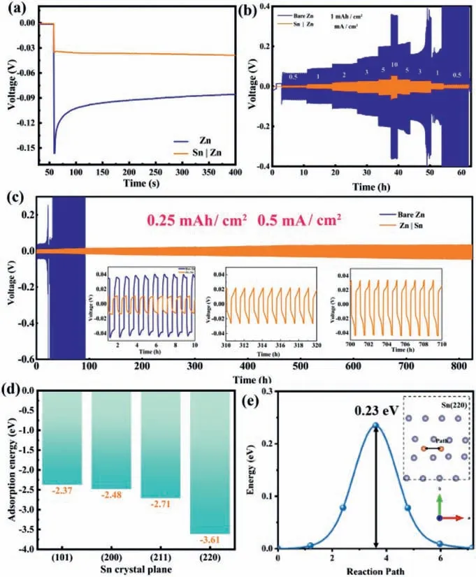
Fig.4.(a) Anode galnovastatic discharging of Zn and Sn|Zn at a capacity of 1 mAh/cm2 and a current density of 10 mA/cm2.(b) Long-term cycling stability at varying current densities.(c) Galvanostatic charge and discharge curves of Zn and Sn|Zn in symmetrical coin cells at 0.5 mA/cm2 (stripping/planting capacity is 0.25 mAh/cm2).(d) The adsorption energy plot of Zn2+ on Sn (101), (200), (211) and(220) planes.(e) Energy barrier profiles along the Zn-ion diffusion paths in Sn (220)plane; insert graph: diffusion paths (indicated by arrows) followed by Zn ion in the Sn (220) plane.
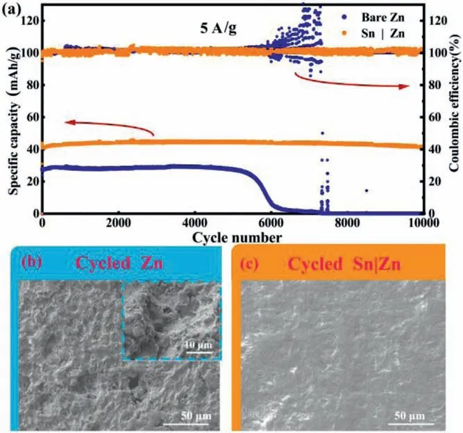
Fig.5.(a) Full cell long-term charging and discharging curves and coulombic effi-ciencies at 5 A/g.The SEM image of cycled (b) polished Zn and (c) Sn|Zn at 5 A/g.
The cycling stability performance of Zn and Sn|Zn were verified in symmetric coin cells with a constant areal capacity of 0.25 mAh/cm2under 0.5 mA/cm2.The symmetric cells with Sn|Zn anodes charge/discharge stably for up to 800 h with a low voltage overpotential (35.6 mV, at 800thhour) (Fig.4c).Charge-discharge profiles in each period are illustrated in the insets of Fig.4c.Sn|Zn electrode presents stable charge and discharge curves all the time,indicating the Sn layer could suppress dendrite growth and HER.Meanwhile, Sn|Zn electrodes also exhibit a more stable cycling performance than Zn foil at 3 and 5 mA/cm2(Figs.S4 and S5 in Supporting information), demonstrating the Sn layer could enhance the cycling stability of the Zn anode effectively.It should be noticed that the Sn|Zn anodes present a competitive electrochemical performance such as prolonged calendar life and low overpotential compared with previous works (Fig.S6 and Table S1 in Supporting information) [26,31,34,38-44].
The DFT calculation was carried out to further confirm the Zn ion adsorption on the Sn surface and diffusion in the Sn layer.The adsorption energy of Zn2+on Sn metallic crystal plane of (101),(200), (211) and (220) are calculated to be −2.37, −2.48, −2.71 and −3.61 eV, respectively.Sn (220) plane has the best affinity toward Zn although all Sn surfaces are of good affinity with Zn2+.Thus, the Zn2+prefers to deposit on the Sn (220).Meanwhile, Sn presents a low migration energy barrier of 0.23 eV along the (220)direction, demonstrating Zn ion on the Sn surface could further diffuse and redistribute (Fig.4e and insert graph).This explains why Sn layer results in a homogeneous Zn deposition and the electrochemical performance enhancement of the composite Sn|Zn electrode.
To further evaluate the potential application of Sn|Zn anode in a full cell system, Sn|Zn anodes were matched with activated carbon (AC) cathodes to assemble ZICs.The typical charge-discharge curves of ZICs with Sn|Zn and Zn foil are shown in Fig.5.The ZIC with Sn|Zn anode exhibits a reversible discharge capacity of 42 mAh/g after 10,000 cycles with almost no decay, compared to the initial discharge capacity (44 mAh/g) and delivers almost 100% of Coulombic efficiency (CE) (Fig.5a).It can be ascribed that little “dead” Zn is produced.In contrast, the cell assembled with Zn foil delivers an initial capacity of 28 mAh/g, much lower than that of Sn|Zn.Its capacity begins to decrease from the 5500thcycle and fails after the 6300thcycle at a current density of 5 A/g.Similarly, the cell assembled with Sn|Zn anodes can sustain an agreeable performance at a current rate of 2 A/g and the cell using Sn|Zn anode can maintain redox cycling for more than 5000 cycles, which is much more than that of the cell using bare Zn anode (1500 cycles) (Fig.S7 in Supporting information).
To explore the reasons for the excellent cycling performance of Sn|Zn, cycled cells were taken apart for analysis by SEM.The surface of the cycled Zn is rugged and bumpy, full of protrusions and corrosion voids, as can be seen in Fig.5b.The OH−ions stemming from HER react with Zn and generate an insulating layer.This layer may cause uneven distribution of charge, leading to inhomogeneous plating of Zn.Thus, the protrusions and corrosion voids are formed on the Zn foil.In contrast, Sn|Zn anode displays a smooth and flat surface (Fig.5c).It is obvious that there are rarely protrusions and rugged areas caused by corrosion on the surface of Sn|Zn (more images in Figs.S8 and S9 in Supporting information),consistent with the effective protection of Sn layer.Consequently,Sn layer vastly prolongs the lifespan of the Sn|Zn anode and uplifts the properties of aqueous Zn ions capacitors.Meanwhile, the main peaks of Sn layer can be clearly observed in the XRD patterns after cycling, suggesting the stability of Sn layer (Fig.S10 in Supporting information).
The specific capacity values of Sn|Zn||AC cell and Zn||AC cell at different rates are illustrated in Fig.6a, and the corresponding charge-discharge curves at different rates are shown in Fig.6b.The reversible capacity values of the Sn|Zn||AC cell are about 45, 42, 38 and 37 mAh/g at current rates of 1, 2, 5 and 10 A/g, respectively.The specific capacity only decreases slightly by 5.47% from the initial value from 0.5 A/g to 1 A/g, demonstrating the remarkable rate ability.Comparing these two anodes at the same rate, the cell with Sn|Zn anode could hold a more stable capacitance than that made of Zn anode, suggesting the enhanced rate ability of Sn|Zn anode.In addition, Zn anode shows severe fluctuation at high rate density(5 A/g).In contrast, the Sn|Zn electrode offers a steady capacity with little capacitance decay.Even at 10 A/g, Sn|Zn electrode exhibits a higher capacity and better stability than Zn.Furthermore,when current density returns to 0.5 A/g, the specific capacity of the Sn|Zn electrode resumes to 47 mAh/g, corresponding to a capacity reversibility of 99.29%.The results of rate performance suggest that the Sn particles not only activated Zn2+reduction but also facilitate the fast transfer of Zn2+through the layer.It is evident that the plating and stripping processes are highly reversible according to the isosceles triangles at different rates (Fig.6b).The chargedischarge profiles of Zn||AC and Sn|Zn||AC capacitors at the current density of 2, 5 and 10 A/g are shown in Figs.S11 and S12 (Supporting information).The Sn|Zn||AC capacitor presents a lower IR drop (59.9, 124.1 and 169 mV at 2, 5 and 10 A/g, respectively) than that of Zn||AC capacitor (120.6, 242.2 and 324.5 mV at 2, 5 and 10 A/g, respectively), which is beneficial for the rate ability.
The reversibility of cells with Zn and Sn|Zn anode was investigated by cyclic voltammetry.The CV curves of the cell with Sn|Zn at various scan rates are shown in Fig.6c (readers are referred to Fig.S13 in Supporting information for the CV curves of cells with Zn anode) with nearly rectangle shape typically observed for capacitor.The increase in capacitance with the scan rate indicates the good rate ability, consistent with that found in Fig.6a.The electrochemical impedance spectroscopy (EIS) of cycled capacitors were tested in coin cell configurations as shown in Fig.6d and the equivalent circuit of EIS Nyquist plot fitting is shown in Fig.6d insert.The EIS demonstrates that Sn|Zn electrode contains a much lower resistance (∼15Ω) than Zn foil (∼805Ω) after cycling 100 times(Fig.6d).The larger resistant of Zn foil is caused by the insulating by-products on the surface of Zn anode [51].
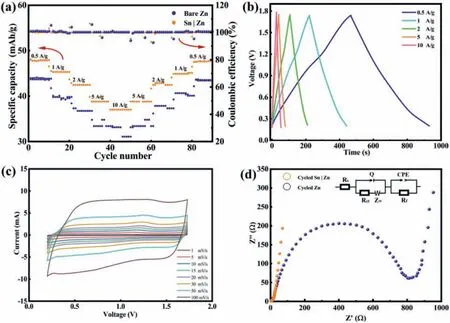
Fig.6.(a) Rate capability at various charge-discharge rates.(b) Charge-discharge curves of Sn|Zn||AC capacitor.(c) Cyclic voltammogram of Zn plating/stripping on Sn|Zn anode at variety scan rates in a coin cell.(d) Nyquist plots of the polished and Sn|Zn anodes before and after cycling.
In summary, a Sn|Zn anode is fabricated by a facile atom exchange strategy.The Sn layer coated on the surface of Zn plays a role of artificial protective film for Zn, which can effectively inhibit corrosion, decrease hydrogen evolution, and induce a homogeneous deposition of Zn.Leveraging these unique properties, the Sn|Zn anode exhibits an extremely low nucleation overpotential(less than 10 mV), a relatively long repeated plating and striping lifespan of 800 h in symmetric Sn|Zn cells.In addition, the full cells paired with AC cathode display a capacity of 44 mAh/g and nearly 100% capacity retention after 10,000 cycles at 10 A/g.The present findings provide a facile and an economic strategy to design and fabricate safe and stable Zn metal electrode toward aqueous Zn ion energy storage devices.
Declaration of competing interest
The authors declare that they have no known competing financial interests or personal relationships that could have appeared to influence the work reported in this paper.
Acknowledgments
This work was partially supported by Hong Kong Scholars Programs (No.XJ2019024), China Postdoctoral Science Foundation(Nos.2018M630340, 2019T120254), Fundamental Research Funds for the Central Universities and National Natural Science Foundation of China (No.22075171).
Supplementary materials
Supplementary material associated with this article can be found, in the online version, at doi:10.1016/j.cclet.2021.11.015.
 Chinese Chemical Letters2022年8期
- Chinese Chemical Letters的其它文章
- Adsorptive removal of PPCPs from aqueous solution using carbon-based composites: A review
- A review on hollow fiber membrane module towards high separation efficiency: Process modeling in fouling perspective
- Recent advances in DNA glycosylase assays
- Chiral pillar[n]arenes: Conformation inversion, material preparation and applications
- Recent progress in carbon-based materials boosting electrochemical water splitting
- Working principle and application of photocatalytic optical fibers for the degradation and conversion of gaseous pollutants