
Ultrathin NiFeS nanosheets as highly active electrocatalysts for oxygen evolution reaction
2022-09-16 05:24YnrongXueMengyunLiuYngyunxingQinYufengZhngXuejingZhngJinjieFngXuZhngWeiZhuZhongbinZhung
Chinese Chemical Letters 2022年8期
Ynrong Xue, Mengyun Liu, Yngyunxing Qin, Yufeng Zhng, Xuejing Zhng,Jinjie Fng, Xu Zhng, Wei Zhu, Zhongbin Zhung,b,∗
a State Key Lab of Organic-Inorganic Composites and Beijing Advanced Innovation Center for Soft Matter Science and Engineering, Beijing University of Chemical Technology, Beijing 100029, China
b Beijing Key Laboratory of Energy Environmental Catalysis, Beijing University of Chemical Technology, Beijing 100029, China
ABSTRACT The development of efficient and cost-effective oxygen evolution reaction (OER) electrocatalysts is crucial for clean energy conversion and storage devices, such as water-splitting, CO2 reduction, and metalair batteries.Herein, we report an efficient 2-dimensional OER catalyst of ultrathin nickel-iron sulfide nanosheets (NiFeS-NS).Dodecanethiol is employed in the synthesis, which prohibits the growth along the Z-axis, thus a nanosheet is obtained.The NiFeS-NS shows high OER catalytic activity, which only requires a small overpotential of 273 mV to achieve the OER current density of 10 mA/cm2 in alkaline electrolyte,and almost no decay after 150 h of chronopotentiometry test.The high performance is attributed to the 2-dimensional structure, the synergistic effect from the Ni and Fe components which promotes the formation of the high valence Ni species, and the tuning effect from the in-situ generated sulfate doping.This work demonstrates the advantages of the 2-dimensional sulfides in electrocatalysis.
Keywords:Nanosheets Nickel Iron Sulfides Oxygen evolution
The increasing depletion of fossil fuels and the massive emission of greenhouse gasses motivate the search for clean and efficient renewable energy sources [1,2].Among the reported energy storage technologies, water electrolysis, CO2reduction, and rechargeable metal-air batteries have been regarded as promising ones, and the oxygen evolution reaction (OER) played an important role in those energy conversion systems [3–6].However, OER is a complex four proton-coupled electron transfer process, and its sluggish kinetics limits the performance of those energy technologies.The reaction kinetics can be accelerated by the rational design of the electrocatalysts, by controlling the composition and structure [7].
RuO2and IrO2based materials possess high catalytic activity,but their high cost and scarcity impede their commercial applications [8–11].Recently, researchers have been focused on earthabundant materials-based OER catalysts [12–14].Many efforts have been devoted to developing non-platinum group metal-based electrocatalysts in different forms, such as spinels [15,16], perovskites[17,18] and mixed-metal oxides [19,20].Ni-based and Fe-based materials are the most extensively studied OER catalysts in alkaline media, and catalysts containing both Ni and Fe exhibit better OER activity [20–23].To further improve the catalytic activity of the catalysts, component control and morphological control may contribute to the performance enhancement [7].To adjust the component of the catalysts, heteroatom doping (e.g., N, S, P) has been studied, in order to enhance the conductivity of the materials and the intrinsic activity of active sites [24–28].For example, sulfur doping can modulate the electronic structure of transition metal, and tune the adsorption energies of the OER intermediates, thus promoting the OER process [21].Fabrication of the catalysts with specific morphology is another way to modulate the catalytic performance.Two-dimensional (2D) materials, also referred to as thin films or nanosheets, are composed of interconnected atoms along the in-plane direction through ionic/covalent bonds,and they are stacked togetherviavan der Waals forces along the out-of-plane direction [29,30].Due to particular crystal structures, the 2D materials exhibited adjustable contact surface area,promoted electrical conductivity and enhanced structure stability,which emerged as promising candidates for energy conversion and storage [31–33].For the OER electrocatalysts, 2D nanosheets of layered inorganic nanomaterials, such as layered double hydroxide(LDH), layered transition metal oxides (TMOs) and transition metal dichalcogenide (TMD) have received more attention due to their outstanding chemical characteristics and excellent electrochemical activity [34,35].Furthermore, the hybridization with 2D inorganic nanosheets can efficiently regulate the electronic structure, chemical bonding nature, and defect structure of active species to further improve its OER performance [36–38].Therefore, it is of significant importance to design and develop low-cost and high-activity OER catalysts by controlling the component and morphology of the catalysts.
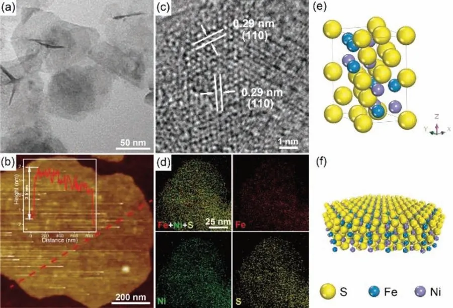
Fig.1.Electromicroscopy characterization of NiFeS-NS.(a) TEM image; (b) AFM image, inset is the height profile of a nanosheet; (c) HRTEM image; (d) EDX elemental mapping images; (e) Scheme of the crystal structure; (f) Scheme of a nanosheet.
Here, we report the synthesis of ultrathin NiFe sulfide nanosheets (named NiFeS-NS), showing excellent OER performance in alkaline electrolyte.The NiFeS-NS shows a low overpotential of 273 mV to deliver an OER current density of 10 mA/cm2in 0.1 mol/L KOH, and it also displays a low Tafel slope of 49 mV/dec.The OER mass activity of NiFeS-NS is 22 and 42 times as high as that of the Ni3S2nanorods (named Ni3S2-NR) and FeS nanosheets(named FeS-NS) at the potential of 1.5 V (vs.reversible hydrogen electrode, RHE, the same hereafter), respectively.Furthermore,the NiFeS-NS shows high stability during the chronopotentiometry measurement at 10 mA/cm2for 150 h.The experimental results show that Fe can adjust the electron structure of Ni sites, and the sulfate-adsorbed NiOOH can be formed on the surface of NiFeS-NS during the OER test, which is beneficial to the OER process.
The NiFeS-NS was synthesized by decomposition of metal thiolates precursors with oleylamine through a wet chemistry.Firstly,the Ni and Fe acetylacetonates were dissolved in dodecanethiol under ultrasonic condition.Then, oleylamine was added and further sonicated to form a uniform solution.Finally, the solution was heated to 200°C for 2 h to produce the NiFeS-NS.The detailed synthesis procedure was described in the Supporting information.
Fig.1a displays the transmission electron microscopy (TEM) image of the as-obtained NiFeS-NS.It reveals the nanosheet structure of the products with the size of a few hundred nanometers.The thickness of the nanosheet is only about 3.5 nm, which is confirmed by the atomic force microscopy (AFM) image shown in Fig.1b.Fig.1c shows the high-resolution TEM (HRTEM) image of the NiFeS-NS.It shows lattice fringes with an interplanar spacing of 0.29 nm.This spacing is slightly smaller than the (110) crystal plane of FeS (0.30 nm, JCPDS card No.75–2165).It suggests the partial replacing of Fe by Ni, because of the smaller ion radius of Ni2+(72 pm) to Fe2+(76 pm).The angle between the two (110) facets is measured asca.120°, which is consistent with the hexagonal crystal cell structure.These results suggest the obtained NiFeS has a hexagonal FeS structure with partial Fe replaced by Ni.Fig.1e shows the crystal structure of the NiFeS.FeS possesses a tetragonal layered structure in which the iron atoms are linked through tetrahedral coordination to four equidistant sulfur atoms.The crystal cell size is about 5.96×5.96×11.7.The FeS sheet is oriented in the 〈001〉 direction.In our synthesis, with the assistant of dodecanethiol, the growth along the 〈001〉 direction was prohibited,thus forming the 2D nanosheet structure.Fig.1f shows the structural model of the obtained NiFeS nanosheet.Based on the cell parameter and the AFM results, the thickness of the nanosheet is about 3 crystal cells along the Z-axis.The energy-dispersive X-ray spectrometry (EDX) elemental mapping images verify the uniform distribution of Ni, Fe and S elements in the nanosheet (Fig.1d).No clear peaks are observed in the XRD pattern (Fig.S1 in Supporting information), probably due to the ultra-thin structure of the obtained NiFeS-NS.The Ni/Fe/S atomic ratio in NiFeS-NS is about 26/22/52 obtained from the EDX.And the Ni/Fe ratio is consistant with the number of 1.2/1 obtained by the inductively coupled plasma mass spectrometry (ICP-MS).
It was found the Fe content is important for the forming of the 2D nanosheet structure.When only Ni acetylacetonate is used and a similar synthetic method is adopted, Ni3S2-NRs are obtained,without forming the products with 2D structure.But when only Fe acetylacetonate is used, FeS-NS is obtained, which indicates that Fe is essential for the formation of the nanosheets.The TEM images of Ni3S2-NR and FeS-NS are shown in Fig.S2 (Supporting information).The obtained Ni3S2-NR has a diameter of about 8 nm and a length of hundreds of nanometers.The HRTEM images (Fig.S3 in Supporting information) show the lattice fringes of the obtained Ni3S2-NR and FeS-NS, respectively.The interplanar spacing of 0.28 nm is assigned to the (110) crystal plane of Ni3S2, and the interplanar spacing of 0.30 nm is assigned to the (110) crystal plane of FeS.The EDX mapping results (Fig.S4 in Supporting information) also suggested the homogeneous sulfides were obtained.The XRD pattern of Ni3S2-NR (Fig.S1) demonstrates the diffraction peaks at 31.1°, 37.9°, 49.8°, 50.3° and 54.7°, which can be indexed to (¯111), (111), (120), (¯120) and (112) planes of Ni3S2(JCPDS card No.76–1870), respectively.Similar to the NiFeS-NS, no clear diffraction peaks can be observed for the XRD pattern of FeS-NS.Furthermore, the Ni/Fe ratio in the nanosheets can be adjusted by the feed ratio of the Ni and Fe acetylacetonates, and a series of nanosheets with different Ni/Fe ratios have been synthesized.The corresponding TEM images are shown in Fig.S5 (Supporting information), and XRD patterns are shown in Fig.S6 (Supporting information).With the introduction of Fe, nanosheets can be successfully synthesized.
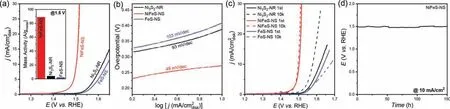
Fig.2.(a) OER polarization curves of the NiFeS-NS, Ni3S2-NR and FeS-NS in O2-saturated 0.1 mol/L KOH electrolyte with a scan rate of 10 mV/s.All the catalysts have a loading of 0.1 mgmetal/cm2.Inset is the OER mass activity at 1.5 V.(b) Tafel plots of the Ni3S2-NR, NiFeS-NS and FeS-NS.(c) OER polarization curves of the Ni3S2-NR, NiFeS-NS and FeS-NS catalysts before and after 10k cycles.(d) The chronopotentiometry curve of the NiFeS-NS at 10 mA/cm2.
The electrocatalytic activities for OER of NiFeS-NS were investigated in O2-saturated 0.1 mol/L KOH solution using a standard three-electrode system.The Ni3S2-NR and FeS-NS were also tested at the same condition for comparison.In order to enhance the conductivity of the catalysts, the materials were supported on reduced graphene oxide (rGO) with a sulfide loading ofca.20%.The catalysts were cast on carbon fiber paper (CFP) with a mass loading of 0.1 mgmetal/cm2and served as the working electrode.Fig.2a shows the OER polarization curves of the NiFeS-NS, Ni3S2-NR and FeS-NS catalysts.All the potentials reported in this work were iR-corrected.The solution resistance measure by AC-impendence spectroscopy and the corresponding Nyquist plots were shown in Fig.S7 (Supporting information).A solution resistance ofca.13Ωwas observed, which is a typical number in 0.1 mol/L KOH.Clearly,the NiFeS-NS shows the highest OER activity than the other catalysts indicating the lowest onset potential and highest current density.The NiFeS-NS shows the OER onset potential of about 1.4 V,and requires a small overpotential of 273 mV to achieve the OER current density of 10 mA/cm2.In comparison, Ni3S2-NR and FeS-NS require the overpotentials of 388 and 409 mV to achieve the same OER current density, respectively.Fig.2b shows the Tafel slope of the catalysts.The Tafel slope of NiFeS-NS is about 49 mV/dec,which is lower than those of Ni3S2-NR (93 mV/dec) and FeS-NS(103 mV/dec), indicating the advantages of NiFeS-NS under high current density conditions.To quantify the OER activity of the catalysts, we calculated the metal-based mass activity at 1.5 V and show in the inset of Fig.2a.The NiFeS-NS has the highest mass activity of 88.9 A/gmetal, which is 22 and 42 times as high as that of the Ni3S2-NR (4.1 A/gmetal) and the FeS-NS (2.1 A/gmetal),respectively.Compared with the previously reported NiFe-based OER electrocatalysts, the NiFeS-NS exhibits superior catalytic performance with a low loading (Table S1 in Supporting information).It demonstrates that the advantages of the Ni, Fe mixed sulfides for OER.The EIS (Fig.S7) also shows the lowestRctof 18Ωfor the NiFeS-NS, which also suggests its highest OER activity.We also calculated the ECSA of the catalysts through the double layer capacitance (Fig.S8 in Supporting information).The ECSA normalized polarization curves were shown in Fig.S9 (Supporting information),indicating the highest intrinsic activity of the NiFeS-NS.We also tested the OER activity of the Ni, Fe mixed sulfides with different Ni/Fe ratios, and the OER polarization curves are shown in Fig.S10(Supporting information).It illustrated that all the Ni,Fe mixed sulfides have better OER performance than the mono metal Ni or Fe sulfides, and the catalyst synthesized with equal Ni/Fe feeding ratio has the best OER performance.
The stability of the catalysts is important for practice applications.We firstly examined the stability of the catalysts by the accelerated CV cycling tests between 1.2 V and 1.7 V with a scanning rate of 50 mV/s, and the results are shown in Fig.2c.After 10,000 CV cycles, the overpotential at 10 mA/cm2slightly decreased for the NiFeS-NS.For the FeS-NS, the overpotential increased 37 mV.Notably, the OER performance of Ni3S2-NR greatly enhanced after 10,000 CV cycles test, and the overpotential decreased 41 mV.This is probably due to the cooperation of the Fe impurity in the KOH electrolyte [39].After the durability test, the catalysts remained their morphologies, indicated by the TEM images shown in Fig.S11 (Supporting information).The OER durability of the NiFeS-NS was also indicated by the chronopotentiometry test at 10 mA/cm2(Fig.2d).The potential was kept at a steady level for the whole 150 h of the test.These results indicate the good OER stability of NiFeS-NS in an alkaline medium.
The sulfides are always considered as a “pre-catalyst” for OER,because of the alkaline electrolyte and the highly oxidative condition when OER occurs [40].Hydroxide ions in the electrolyte could easily migrate to the surface of sulfides, then be exchanged with sulfide ions to form surface metal hydroxides or oxides [41].Surface oxides or hydroxides are proposedin-situgenerate and work as the real active sites for OER.We investigated the surface condition of the catalyst after the OER test in order to understand the origin of the OER current.Fig.3 shows the high-resolution XPS spectra (XPS) of the catalysts before and after OER tests.For the Ni 2p spectra, the peak at 853.9 eV and 870.1 eV for the Ni3S2-NR was assigned to the Ni2+2p3/2and Ni2+2p1/2species, respectively.After OER cycling, the peak positively shifted by 1.2 eV to 855.1 eV,which corresponds to the Ni3+species [42,43].Compared with Ni3S2-NR, the binding energy of Ni of NiFeS-NS significantly positively shifted by 1.9 eV to 855.8 eV (Fig.3a), indicating that Fe regulates the electronic structure of Ni, and the higher binding energy of Ni is conducive to the OER process [44].Fig.3b shows the Fe 2p XPS spectra of FeS-NS and NiFeS-NS.For FeS-NS, the peaks at 710.4 and 724.1 eV are ascribed to the Fe2+2p3/2and 2p1/2, respectively.The small peak at 712.4 eV was corresponding to the Fe3+2p3/2,which is due to Fe2+in FeS being oxidized by air [45].The increase in the proportion of Fe3+further indicates that FeS was oxidized during the OER test.However, for the NiFeS-NS, the proportion of Fe3+species is much smaller for both before and after OER test.It suggests the electronic effect between Ni and Fe.The electron transfer from Ni to Fe, thus more Ni(III) species and fewer Fe(III)species were found in the NiFeS-NS.Ni has been widely recognized as the main OER active site for NiFe-based materials [46–48].The high valance Ni species were considered beneficial for the OER processes, which makes the binding energy of the OER reaction intermediate (∗OH,∗O,∗OOH,etc.) on the Ni sites more optimized and facilitated O2desorption from Ni sites.The introduction of the Fe promotes the oxidation of Ni to Ni(III) species, thus higher OER performance of NiFeS-NS was achieved [21,35].
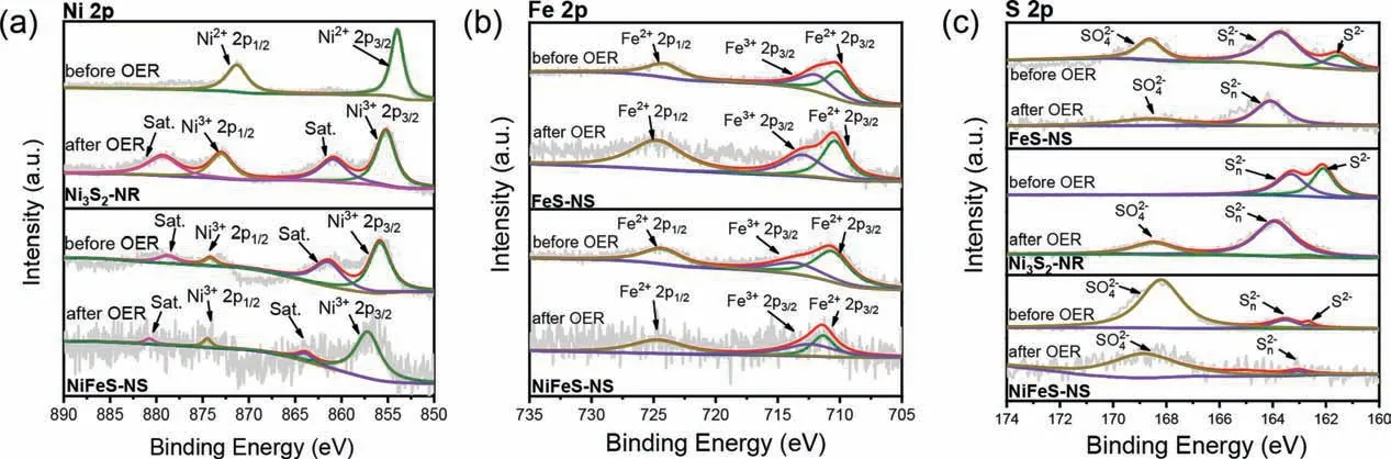
Fig.3.High-resolution (a) Ni 2p, (b) Fe 2p and (c) S 2p XPS spectra of the Ni3S2-NR, NiFeS-NS and FeS-NS catalysts before and after OER tests.
The role of S was investigated as well.Fig.3c shows the S 2p XPS spectra of the catalysts.For NiFeS-NS, the peaks at 162.2 and 163.3 eV are assigned to sulfide (S2−) and polysulfides (Sn2−)species, respectively [49].The additional peak at 168.7 eV is ascribed to SO42−, which indicates the catalyst oxidized when exposed to the air [50].For Ni3S2-NR, the peak attributed to SO42−at 168.5 eV only appears after the OER test, which demonstrates the oxidation of the Ni3S2more difficult [8].For the materials with nanosheet structures (NiFeS-NS and FeS-NS), the peak attributed to SO42−already appears before the OER test.It demonstrates that nanosheets are easier to be oxides.This may be a reason that the NiFeS-NS has high OER performance.After OER test,the peak assigned to the S2−almost disappeared, demonstrating the heavy surface oxidation of nanosheets under the OER condition, and SO42−is adsorbed on its surface.Zhanget al.reported that NiS2oxidated to be NiOOH at 1.63 V, and adsorption of sulfates on NiOOH can dramatically enhance the OER activity [51].Liet al.reported that the sulfate-functionalized Ni(OH)2nanobelt surface gradually forms highly active NiOOH/Ni(SO4)0.3(OH)1.4composite during the OER test, which is beneficial for reducing the OER reaction overpotential [52].The surface adsorbed SO42−adjusted the electronic structure of the Ni sites, and promotes the OER activity.
In summary, we successfully synthesized 2D ultrathin NiFe sulfide nanosheets as effective OER electrocatalysts.The obtained NiFeS-NS exhibited a low overpotential of 273 mV to achieve the OER current density of 10 mA/cm2with a low Tafel slope of 49 mV/dec in 0.1 mol/L KOH.The OER mass activity at 1.5 V of NiFeS-NS is 22 and 42 times as high as that of Ni3S2-NR and FeS-NS, respectively.The high OER performance is attributed to the unique 2D structure of NiFeS-NS, the electronic regulation from Fe that facilitated the adsorption of the OER intermediates on Ni sites,and the enhancement from the sulfate-adsorbed NiOOH.It demonstrated the well-designed 2D nanomaterials are promising for electrocatalysis.
Declaration of competing interest
The authors declare that they have no known competing financial interests or personal relationships that could have appeared to influence the work reported in this paper.
Acknowledgments
This work was supported by the National Key Research and Development Program of China (No.2019YFA0210300), National Natural Science Foundation of China (No.21971008), Fundamental Research Funds for the Central Universities (Nos.buctrc201916,buctrc201823).
Supplementary materials
Supplementary material associated with this article can be found, in the online version, at doi:10.1016/j.cclet.2021.11.085.
 Chinese Chemical Letters2022年8期
- Chinese Chemical Letters的其它文章
- Adsorptive removal of PPCPs from aqueous solution using carbon-based composites: A review
- A review on hollow fiber membrane module towards high separation efficiency: Process modeling in fouling perspective
- Recent advances in DNA glycosylase assays
- Chiral pillar[n]arenes: Conformation inversion, material preparation and applications
- Recent progress in carbon-based materials boosting electrochemical water splitting
- Working principle and application of photocatalytic optical fibers for the degradation and conversion of gaseous pollutants