
Fe3C coupled with Fe-Nx supported on N-doped carbon as oxygen reduction catalyst for assembling Zn-air battery to drive water splitting
2022-09-16 05:24GungyingZhngXuLiuPengYuDiShenBowenLiuQiwenPnLeiWngHonggngFu
Chinese Chemical Letters 2022年8期
Gungying Zhng, Xu Liu, Peng Yu, Di Shen, Bowen Liu, Qiwen Pn, Lei Wng,∗,Honggng Fu,∗
a Key Laboratory of Functional Inorganic Material Chemistry, Ministry of Education of the People’s Republic of China, Heilongjiang University, Harbin 150080, China
b Key Laboratory for Photonic and Electronic Bandgap Materials, Ministry of Education, School of Physics and Electronic Engineering, Harbin Normal University, Harbin 150025, China
ABSTRACT Fe-N-C structures have been considered as a candidate to replace noble metal catalysts towards oxygen reduction reaction (ORR) due to their excellent electrocatalytic activity and durability.Herein, a zincmediated synthesis strategy is proposed for N-doped graphitic porous carbon encapsulated uniform dispersed Fe3C nanoparticles coupled with atomically dispersed Fe-Nx moieties (NPC/Fe-N-C) derived from biomass coconut shell.The introduction of zinc species could be conductive to the dispersion of iron species and formation of porous structures.Density functional theory calculations demonstrate that the N-doped carbon coating structures can weaken the oxygen intermediates adsorption energy barrier of Fe3C.Beside, the graphitic carbon could promote the electron transfer during the electrochemical reaction.These special structures enable NPC/Fe-N-C to have excellent ORR activity with an Eonset of 1.0 V,which is much better than Pt/C.Furthermore, the zinc-air battery assembled by pairing NPC/Fe-N-C with a high-efficiency oxygen evolution reaction (OER) catalyst can continuously and stably operate a chargedischarge potential gap of 0.8 V at 10 mA/cm2 for more than 600 h.More importantly, the assembled batteries could drive overall water splitting device, realizing the effective energy conversion.
Keywords:Biomass Iron-based catalyst Synergy Oxygen reduction Zn-air battery
Development of efficient energy storage and conversion equipment is an effective mean to alleviate the energy crisis and environmental pollution.Nevertheless, the driving force required by these devices will constrain sustainable development strategy [1,2].For instance, electrochemical water splitting is usually powered by industrial electricity, which will increase carbon emissions and not conductive to sustainable development.Therefore, considerable efforts have been devoted to explore clean energy-driven water splitting devices, such as solar energy and rechargeable batteries [3–6].Zn-air batteries (ZABs) exhibit high theoretical energy density, environmental friendliness, safety, low cost and long durability, that maybe use as an effective power supply for other energy devices,such as water splitting [7,8].As an important discharging process of ZABs, oxygen reduction reaction (ORR) is a kinetically slow process due to the complex reaction path with many intermediates[9–11].Its overpotentials significantly affect the power output and round-trip efficiency of ZABs [12].Up to now, precious Pt-based catalysts are still regarded as the most effective catalysts for ORR[13,14].However, the serious scarcity and expensive cost restrain their large-scale commercial applications.It is essential to develop low-cost, renewable energy and earth-rich materials to prepare non-precious catalysts for replacing Pt-based catalysts.
Metal-nitrogen-carbon (M-N-C) structures stand out as efficient catalysts among various non-precious catalysts, which occupy the research forefront in electrocatalytic field [15–18].Particularly, the Fe-N-C structure could accelerate kinetics and effectively improve the electrocatalytic activity of ORR owing to their plentiful active sites and synergistic effect [19–21].Generally, the synthetic Fe-NC structures containing Fe3C nanoparticles (NPs) and atomically Fe-Nxactive sites [22].Recently, Weiet al.designed a grapheneencapsulated Fe3C NPs with Fe-Nxsites as for excellent ORR catalyst.It had been demonstrated that the synergistic effect of the two iron species could promote the oxygen adsorption and intermediates dissociation [23].Moreover, the carbon encapsuled Fe3C structures can further enhance the stability and activity [24–28],but the reason is not well understood.Most guesses suggested that the encapsulated Fe3C NPs can cause the unique host-guest electronic interaction, change the local working function of the carbon layer, thus activate the outer surface of the carbon layer, thus activate the outer surface of the carbon layer and improve ORR activity[29,30], but this is rarely confirmed by data.The traditional synthetic route of Fe-N-C structures is to pyrolyze the precursors containing iron and nitrogen species, such as porphyrin [31], polyaniline skeleton precursors [32], but the metal species are easily to aggregate during the pyrolytic process, and the formation of atomically dispersed Fe sites is too difficult.Nowadays, metal organic frameworks (MOFs) have been explored as an effective precursor for preparing uniform dispersion M-N-C catalysts due to the interaction between ligands and metal ions could be tuned [33,34].Usually, the zeolitic imidazolate frameworks-8 (ZIFs-8) structures contained Zn species are used to synthesize atomically dispersed M-N-C structures, because the Zn evaporation during heat treatment could benefit the highly dispersion of metal species [9,35,36].However, the expensive cost of ligands is not conductive to the preparation and applications on a largescale.Therefore, it is necessary to explore simple and low-cost synthetic routes to fulfill the sustainable development strategy.Biomass is a substance rich in carbon, which can be used as an effective carbon source to synthesize various carbon materials.For coconut shell, the inner vessel is mainly composed of cellulose fibers, which could coordinate with different metal ions for preparing carbon-based material [37].It is still challenging but great value for the development of energy devices to prepare Fe-N-C catalyst with both metal nanoparticles and single atoms derived from coconut shell.
Herein, a sustainable and effective strategy by using biomass as carbon source is proposed to prepare N-doped graphitic porous carbon encapsulated uniform dispersed Fe3C nanoparticles coupled with atomically dispersed Fe-Nxmoieties (NPC/Fe-N-C).The evaporation of Zn could form plentiful porous structures and benefit to highly dispersion of iron species.DFT calculations indicate that the N-doped carbon encapsulated Fe3C NPs can weaken the intermediates adsorption energy barrier of ORR.As for primary ZAB, the battery exhibits high open-circuit voltage, high power density and long-term durability, superior to Pt/C catalyst.The rechargeable ZAB requires excellent both ORR and OER performances with a low charge-discharge potential gap.The combination of high-activity ORR catalyst and high-activity OER can minimize the charge-discharge potential gap and maximize the performance of the ZABs.Therefore, the rechargeable ZAB is assembled by combining NPC/Fe-N-C with iron foam supported NiFe-LDH (NiFe-LDH@FF) as air-cathode, which shows a lower potential gap of 0.80 V at 10 mA/cm2and a longer cycle life for continuous stable operation over 600 h, outperforming the Pt/C+RuO2battery.Significantly, two batteries connected in series can power an overall water splitting device with high efficiency.This work may pave an avenue for the design and development of highly efficient electrocatalysts with low cost and promote the practical application of ZAB.The synthetic process of NPC/Fe-N-C is shown in Fig.1a.The cellulose was firstly extracted from coconut shells by a traditional alkaline hydrothermal route, which exhibited fibrous structures (Fig.S1 in Supporting information).Then, the obtained cellulose was coordinated with Fe2+and Zn2+ions.After evaporating under heating treatment, the precursor was pyrolyzed in N2/NH3mixture atmosphere at 900 °C for N-doping, accompanied by the crystallization of Fe and carbon species, and partial evaporation of Zn species.Subsequently, an acid treatment to remove extra Fe and Zn species, followed by another heat treatment was performed at 1100 °C to further disperse Fe species for preparing NPC/Fe-N-C.Transmission electron microscopy (TEM) was used to characterize the microstructures.As shown in Figs.1b and c, the uniform dispersed small nanoparticles around 20–30 nm coated with carbon nanosheet structures can be observed for NPC/Fe-NC.High-resolution TEM (HRTEM) shows obvious micropore structures (<2 nm) (Figs.1d and e), which could provide more effective active centers and shorten mass transfer pathways [4,38,39].The generation of micropores is due to the high temperature decomposition of zinc in the precursor.The interplanar spacing of 0.21 and 0.34 nm correspond to the (211) plane of Fe3C and (111) plane of graphitic carbon, respectively [22].The 5 nm thick carbon layer wrapped structure would prevent Fe3C nanoparticles from dissolving during the electrochemical reaction, thereby retaining the catalytic activity for a long time [26].
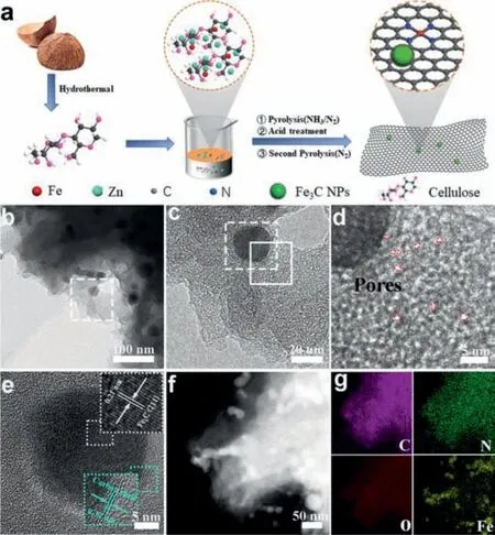
Fig.1.(a) Synthetic scheme of NPC/Fe-N-C.(b, c) TEM, (d, e) HRTEM, (f) STEM images and (g) the corresponding EDX element mappings of NPC/Fe-N-C.
The scanning TEM (STEM) image and energy dispersive Xray (EDX) elemental mappings in Figs.1f and g display the uniform distribution of C, N and O elements in the whole area of NPC/Fe-N-C.In addition, most of the Fe element is concentrated in the nanoparticles area, meanwhile partially single dispersed Fe distributes in the carbon layer, indicating that both nanoparticles and atomic-level Fe exist in NPC/Fe-N-C.For comparison,the NC/Fe3C was synthesized without using zinc chloride.As the TEM image shown in Fig.S2 (Supporting information), NC/Fe3C displays a nanocapsule-like structure due to iron the aggregation of metal nanoparticles during pyrolysis, further demonstrating the zinc species not only benefit to the uniform disperse during the pyrolytic process, but also could produce porous structures.X-ray diffraction (XRD) was performed to study the crystal structure.The diffraction peaks in NPC/Fe-N-C are assigned to Fe3C (PDF #35-0772) and graphitic carbon (PDF #26-1079) (Fig.2a).Compared with NC/Fe3C, NPC/Fe-N-C has an extra wide at around 20°–30°,corresponding to the amorphous carbon.It is attributed to the addition of zinc chloride could affect the crystalline of carbon nanostructures, which is consistent with TEM results.
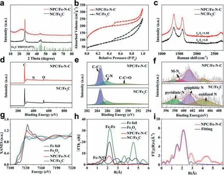
Fig.2.(a) XRD patterns, (b) N2 sorption isotherms and (c) Raman spectra of NPC/Fe-N-C and NC/Fe3C.(d) Wide XPS spectra, high-resolution XPS spectra of (e) C 1s and (f)N 1s for NPC/Fe-N-C and NC/Fe3C.(g) Normalized Fe K-edge XANE spectra and (h) Fourier transform Fe K-edge EXAFS spectra of Fe foil, Fe2O3, NC/Fe3C and NPC/Fe-N-C.(i)FT-EXAFS fitting curves of Fe K-edge for NPC/Fe-N-C.
N2sorption isotherms were tested to assess the Brunauer–Emmett–Teller (BET) surface area and porous structures (Fig.2b).NPC/Fe-N-C exhibits typical type IV curve with a significant increase of quantity adsorption at a relatively low N2pressure(P/P0= 0–0.2) and a clear hysteresis loop at a higher N2pressure (P/P0= 0.45–0.95), indicating the coexistence of micropores and mesopores [40,41].The NPC/Fe-N-C shows a higher BET surface area of 630.6 m2/g than NC/Fe3C (236.0 m2/g).Furthermore,the specific surface area is gradually increase with the increase of zinc chloride (Fig.S3 and Table S1 in Supporting information).It can be attributed to the zinc evaporation at high-temperature could leave large pores in the carbon substratein situ.Raman spectrum in Fig.2c exhibits two peaks located at around 1348 and 1585 cm–1, which are assigned to D-band and G-band, respectively [42].The G-band is ascribed to sp2orbital of aromatic structures, while D-band corresponds to disordered or defective carbon nanostructures [43,44].TheID/IGratio of NPC/Fe-N-C is higher than NC/Fe3C, implying the higher defective degree of NPC/Fe-N-C.The abundant defective sites can coordinate electronic structure and surface property of NPC/Fe-N-C, and optimize the adsorption energy of different electrochemical reaction steps [45].
X-ray photoelectron spectroscopy (XPS) measurements were carried out to analyze the chemical composition.The wide spectra in Fig.2d prove that both NPC/Fe-N-C and NC/Fe3C are composed of C, N and O elements.No iron signal could be detected due to the Fe nanoparticles is completely covered by the graphitic carbon layer.The Fe content of NPC/Fe-N-C obtained by inductively coupled plasma optical emission spectrometry (ICP-OES) is about 0.64%.Almost no zinc was detected from XPS, ICP and XANES characterization, confirming the complete removal of zinc species.As the high-resolution C 1s spectrum of NPC/Fe-N-C displayed in Fig.2e, the three peaks located at 284.6, 285.8 and 289.1 eV are assigned to C-C, C-N and C-C=O bonds, respectively [46].The existence of C-N bond indicates that N is successfully incorporated into the carbon nanostructures.The high-resolution N 1s spectrum can be fitted with four peaks centered at 398.1, 399.3, 401.2 and 404.5 eV (Fig.2f), respectively corresponding to pyridinic N, MNx, graphitic N and oxidized N for NPC/Fe-N-C.The presence of the M-Nxspecies indicates that the Fe species interact with the surrounding N to form highly dispersed Fe-Nx, which is consistent with the above TEM results.It further shows that ZnCl2promotes the dispersion of iron species.Beside, the large amount of graphitic N would improve the conductivity and benefit to electron transport[47,48].
X-ray absorption near-edge structure (XANES) and k3-weighted Fourier transformation of Fe K-edge from normalized extended Xray absorption fine structure (FT-EXAFS) were carried out to further investigate the structure and coordination information.The XANES of NPC/Fe-N-C in Fig.2g shows slightly higher white lines compared with Fe foil and lower than Fe2O3, suggesting that the Fe species in NPC/Fe-N-C possesses low-valent oxide state [49,50].The FT-EXAFS spectra were illustrated in Fig.2h.In additional to the strong Fe-Fe signal located at ∼2.1, one weak peak located at ∼1.5is attributed to Fe-N/O first coordination shell and match well with FePc, confirming the atomically dispersed Fe-Nxspecies exist in NPC/Fe-N-C [51,52].The intensity ratio of Fe-N to Fe-Fe bond increased after introduction of zinc source, demonstrating the Fe-Nxcontent is increase in NPC/Fe-N-C.The XAFS results are consistent with above TEM analyses.The fitting EXAFS spectrum manifests that the coordinated number and bond length for Fe and N are 4.8 and 1.96, respectively (Fig.2i and Table S2 in Supporting information).
Density functional theory (DFT) calculations were used to estimate the effect of carbon layer coating on the ORR process.The Fe3C (211) plane was selected as the calculated model based on the above TEM analyses.Three geometric optimization structural models of the Fe3C@NC-N (O2adsorbed onto the N site of N-doped carbon coating), Fe3C@NC-C (O2adsorbed onto the C site of N-doped carbon coating), Fe3C (O2adsorbed onto the Fe site) were constructed as shown in Figs.3a–c and Figs.S4 and S5 (Supporting information).The corresponding O2adsorption energies (Eads) for the three models are –4.818 eV, –4.852 eV and –5.545 eV, respectively,demonstrating all the O2adsorption are spontaneous (Table S3 in Supporting information).The O–O bond obviously lengthens from 1.24to 1.48after O2adsorption on Fe3C@NC-N, implying that the O2cleavage easily occurs on the surface of Fe3C@NC-N.The density of states (DOSs) for O2molecule adsorption in Fe3C@NCN, Fe3C@NC-C models and Fe3C models were illustrated in Fig.3d.The O2pstates of Fe3C@NC-N/C exhibits a lower energy position compared with the Fe3C system.The more electrons filling theπ∗orbits of O2will promote the cleavage of the O–O bond [53], resulting in a promoted ORR activity.
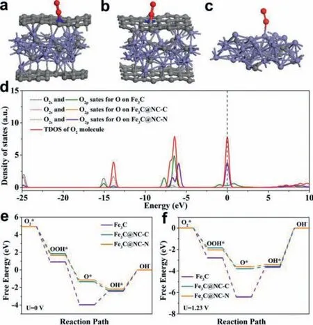
Fig.3.The optimized structures for O2 adsorption on (a) Fe3C, (b) Fe3C@NC-C and(c) Fe3C@NC-N.(d) Density of states (DOSs) for the O2 molecules on different adsorption sites.(e, f) Free energy diagrams of the ORR on Fe3C, Fe3C@NC-C and Fe3C@NC-N at potentials of 0 and 1.23 V.
For further validate the ideal active center, Gibbs free energy(ΔG) of O2intermediates on different steps were calculated at redox potential (0 V and 1.23 V) as displayed in Figs.3e and f.The formation of OOH∗exhibits highestΔG, which is considered to be the rate-determining step (RDS) during the whole ORR reaction.Compared to the Fe3C@NC-C and Fe3C, the Fe3C@NC-N has the lowest energy barrier, indicating the adsorbed O2can easily desorb on the Fe3C@NC-N sites.These results suggest the Fe3C@NC-N is the superior active site for ORR.According to the Bader charge analyses, the Fe atoms in Fe3C@NC can transfer some electrons to N/C atoms of NC (Table S4 in Supporting information).It is proved that Fe atoms can increase the electronegativity of N/C atoms, promoting the absorption of intermediates and the breaking of O–O bonds.
The ORR performance was evaluated by cyclic voltammetry (CV)and linear sweep voltammetry (LSV) in O2-saturated 0.1 mol/L KOH electrolyte.All potentials were referenced to the RHE.As can be seen from Fig.4a, NC/Fe3C exhibits an onset potential (Eonset) of 0.96 V, half-wave potential (E1/2) of 0.82 V and limiting current density of 4.4 mA/cm2towards ORR.Relatively, NPC/Fe-N-C catalyst exhibits the best ORR catalytic activity with anEonsetof 1.0 V,anE1/2of 0.87 V and limiting current density of 5.2 mA/cm2,much higher than those for Pt/C and NC/Fe3C (Fig.4b), implying the introduction of zinc source greatly improved ORR performance.The excellent activity of NPC/Fe-N-C catalyst is attributed to the synergistic effect of Fe3C and Fe-Nx, accompanying by the porous structure benefit to the efficient O2diffusion and mass transport.The catalysts synthesized from different zinc chloride dosage were also compared (Fig.S6 and Table S5 in Supporting information).Obviously, NPC/Fe-N-C performs the optimal activity with the highestEonsetandE1/2due to its moderate iron content and BET surface area.Furthermore, NPC/Fe-N-C shows a lower tafel slope of 49 mV/dec compared to Pt/C (53 mV/dec) and NC/Fe3C (80 mV/dec) (Fig.4c), clarifying faster kinetics possesses.Rotating ring-disk electrode (RRDE) technique was further used to detect the H2O2and electron transfer number (n) during the ORR process as illustrated in Fig.4d.NPC/Fe-N-C exhibits an ideal four-electron with a lower hydrogen peroxide yield of 5.0% than that of Pt/C (Fig.4e), indicating the O2is effectively reduced to H2O.Meanwhile, Koutecky-Levich (K-L) plots obtained from linear sweep voltammetry (LSV) curves at different rotation rates were described in Fig.4f.The linear and almost parallel K-L plots at potential range of 0.3–0.5 V can be obtained in Fig.4g, demonstrating NPC/Fe-N-C exhibit first order kinetics of dissolved oxygen concentration with a direct four-electron transfer pathway.
For further insight into the electrocatalytic active sites of NPC/Fe-N-C, the selective poisoning experiments with SCN–was implemented as displayed in Fig.4h.After addition of 0.01 mol/L SCN−in 0.1 mol/L HClO4electrolyte, NPC/Fe-N-C shows negatively shiftE1/2of more than 100 mV due to SCN−block the Fe active sites.It is suggested that the Fe sites is the main active sites of NPC/Fe-N-C for ORR.Beside, the durability is another essential aspect for evaluating ORR performance of an electrocatalyst.As shown in Fig.4i, NPC/Fe-N-C exhibits only 18 mV negative shift ofE1/2after 10000 cycles, which is much smaller than that of Pt/C(44 mV) (Fig.S7 in Supporting information), confirming an excellent ORR stability.It is attributed to the N-carbon coating structures could restrain the dissolution and shedding of active iron species during the electrochemical test.The stability was further assessed by chronoamperometry (CA) test.NPC/Fe-N-C performs obviously low current attenuation compared with Pt/C (Fig.S8 in Supporting information), further indicating its well stability.Moreover, NPC/Fe-N-C shows a higher ORR activity than most of the recently reported Pt-free catalysts (Table S6 in Supporting information).The outperforming ORR activity of NPC/Fe-N-C ascribes to the three main factors: (1) Fe3C coated with N-doped carbon structures can weaken the intermediates adsorption barrier and inhibits the dissolution of Fe3C NPs.(2) The synergy between Fe3C and atomically dispersed Fe-Nxspecies could enhance the electrocatalytic activity.(3) The plentiful porous structures can effectively accelerate the proton transport.
Consideration the superior ORR performance of NPC/Fe-N-C, it was further employed to assemble ZAB (Fig.5a).As shown in Fig.5b, the primary ZAB constructed by using NPC/Fe-N-C as airelectrode exhibits a higher open circuit voltages of 1.59 V than that of Pt/C battery (1.51 V).The galvanostatic discharge profiles are illustrated in Fig.5c.NPC/Fe-N-C battery can continuously discharge for 95 h at a current density of 10 mA/cm2with a high specific capacity of 802 mAh/gZn.Furthermore, Fig.5d indicates the NPC/Fe-N-C battery possess excellent discharge rate performance.Even at a high current density of 50 mA/cm2, the potential is still above 1.0 V (higher than Pt/C battery), demonstrating the application prospect in high current energy storage devices.After the large current density discharging, the performance can be recovered when the current density is reduced to 2 mA/cm2, verifying the good reversibility of NPC/Fe-N-C battery.
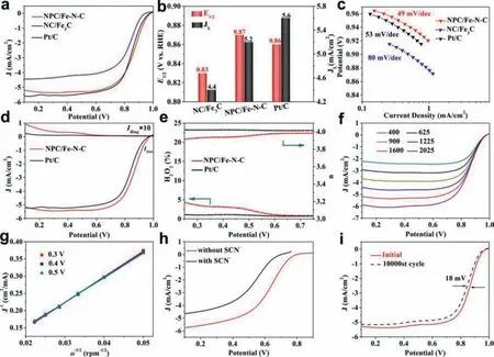
Fig.4.(a) LSV curves, (b) JL and E1/2, (c) corresponding Tafel plots of NPC/Fe-N-C, NC/Fe3C and commercial Pt/C catalysts tested in O2-saturated 0.1 mol/L KOH electrolyte at 1600 rpm with a sweep rate of 5 mV/s.(d) RRDE curves, (e) H2O2 yield and the electron transfer number of NPC/Fe-N-C and Pt/C.(f) LSV curves tested at rotation speeds from 400 rpm to 2025 rpm.(g) K,L plots of J−1 versus ω−1/2 at different potentials.(h) LSV curves of NPC/Fe-N-C recorded in O2-saturated 0.1 mol/L HClO4 before and after injecting 0.01 mol/L SCN−.(i) Stability test of NPC/Fe-N-C before and after 10,000 cycles.
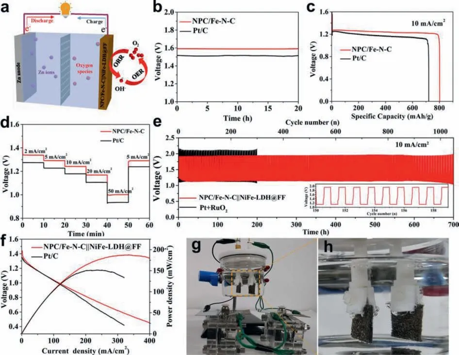
Fig.5.(a) Schematic diagram of ZAB.(b) Open-circuit voltages, (c) specific discharging capacities for primary ZABs assembled by NPC/Fe-N-C and Pt/C at 10 mA/cm2.(d)Discharge curves of the primary ZAB based on NPC/Fe-N-C and Pt/C with current densities of 2−50 mA/cm2.(e) Cyclic performance of rechargeable ZABs with a duration of 40 min per cycle at 10 mA/cm2 for NPC/Fe-N-C||NiFe-LDH@FF and Pt/C + RuO2.(f) Discharge polarization curves and power density curves.(g, h) Two NPC/Fe-N-C||NiFe-LDH@FF-based ZABs connected in series power a water-splitting device.
To further demonstrate the practical application in energy devices, the rechargeable ZAB was assembled by the air-cathode composed of NPC/Fe-N-C as ORR electrocatalysts and NiFe-LDH@FF as oxygen evolution reaction (OER) electrocatalysts.The NiFe-LDH@FF was synthesized by a simple hydrothermal route, and the corresponding structural characterization and OER performance tests are displayed in Figs.S9–S11 (Supporting information).The NPC/Fe-N-C||NiFe-LDH@FF battery exhibits an initial discharge and charge voltage gap (ΔE) of 0.80 V, which is much smaller than the Pt/C+IrO2battery (1.0 V).Additionally, NPC/Fe-N-C||NiFe-LDH@FF battery could be continuously stable running 900 cycles (over 600 h) at a constant discharging and charging current density of 10 mA/cm2, much better than Pt/C+RuO2battery (Fig.5e).The NPC/Fe-N-C||NiFe-LDH@FF battery unfolds a higher maximum power density of 187 mW/cm2than that of Pt/C+RuO2battery (Fig.5f).Furthermore, NPC/Fe-N-C||NiFe-LDH@FF battery could power a 1.5 V electronic watch (Fig.S12 in Supporting information), indicating the practical applications.The NPC/Fe-N-C||NiFe-LDH@FF battery exhibits a higher performance than recently reported non precious metal base batteries as listed in Table S7 (Supporting information).Water splitting device can realize the effective energy conversion from chemical energy to electric energy and clean fuel gas (H2) [54].However, at present, many water splitting devices use industrial electricity to supply electricity and consume large amounts of energy, which in not conductive to the sustainable development.Since the potential of the NiFe-LDH@FF-based overall water splitting device is 1.63 V at 10 mA/cm2(Fig.S13 in Supporting information), the discharge potential of the NPC/Fe-NC||NiFe-LDH@FF ZAB is over 1.2 V at 10 mA/cm2, and two ZABs connected in series are sufficient for driving water splitting device.Then, an overall water splitting device by using NiFe-LDH@FF as both anode and cathode was constructed.It can be obviously seen that two NPC/Fe-N-C||NiFe-LDH@FF batteries connected in series could power the device, meanwhile, hydrogen and oxygen bubbles are visible on both electrodes (Figs.5g and h).The result demonstrates that the NPC/Fe-N-C||NiFe-LDH@FF battery can be applied as an effective power supply to drive water splitting device.
In summary, we focus on the utilization of natural waste renewable biomass as raw material for preparing carbon-based metal composites electrocatalysts, which can be used to assemble ZAB for energy storage and ultimately drive the water splitting device.The NPC/Fe-N-C composed of N-doped porous carbon encapsulated Fe3C and atomically dispersed Fe-Nxhas been constructed by adopting biomass as carbon resource.It exhibits excellent ORR activity and durability in alkaline solution, outperforming Pt/C catalyst.Meanwhile, the primary NPC/Fe-N-C ZAB shows superior discharge capability and stability.Furthermore, the rechargeable NPC/Fe-N-C||NiFe-LDH@FF ZAB delivers a superior durability over 600 h, which can be used as power supply to drive overall water splitting, demonstrating the practical application value of ZAB.
Declaration of competing interest
The authors declare no conflict of competing interest.
Acknowledgments
We gratefully acknowledge the support of this research by the National Key R&D Program of China (No.2018YFB1502401),National Natural Science Foundation of China (Nos.22179034,21771059, 21631004), Natural Science Foundation of Heilongjiang Province (No.YQ2019B007).
Supplementary materials
Supplementary material associated with this article can be found, in the online version, at doi:10.1016/j.cclet.2021.11.075.
 Chinese Chemical Letters2022年8期
- Chinese Chemical Letters的其它文章
- Adsorptive removal of PPCPs from aqueous solution using carbon-based composites: A review
- A review on hollow fiber membrane module towards high separation efficiency: Process modeling in fouling perspective
- Recent advances in DNA glycosylase assays
- Chiral pillar[n]arenes: Conformation inversion, material preparation and applications
- Recent progress in carbon-based materials boosting electrochemical water splitting
- Working principle and application of photocatalytic optical fibers for the degradation and conversion of gaseous pollutants