
The effect of electrolyte additives on the rate performance of hard carbon anode at low temperature for lithium-ion capacitor
2022-09-16 05:24JianminYuanNanQinYanyanLuLimingJinJunshengZhengJimZheng
Chinese Chemical Letters 2022年8期
Jianmin Yuan, Nan Qin, Yanyan Lu, Liming Jin, Junsheng Zheng,∗, Jim P.Zheng
a Clean Energy Automotive Engineering Center, Tongji University (Jiading Campus), Shanghai 201804, China
b School of automotive studies, Tongji University (Jiading Campus), Shanghai 201804, China
c Department of Electrical Engineering, University at Buffalo, The State University of New York, Buffalo, New York 14260, United States
ABSTRACT Lithium-ion capacitor (LIC), which combines the advantages of lithium-ion battery (LIB) and electrical double layer capacitor (EDLC), has a rapid development during last decade, however, the poor low temperature performance still limits its application.In this paper, three electrolyte additives including vinylene carbonate (VC), fluoroethylene carbonate (FEC) and 1,3,2-dioxathiolane 2,2-dioxide (DTD) have been utilized and their effects on the rate performance of hard carbon (HC) anode of LIC at various temperatures ranging from 25 °C to −40 °C have been well evaluated.The cell containing FEC shows the best rate performance at various temperatures and has the charge and discharge capability even at −40 °C.For HC anode, the charge transfer impedance (RCT) increases exponentially at low temperature, while the equivalent series resistance (Rs) and the impedance of solid electrolyte interface (SEI) increase relatively few.At low temperatures, the effect of FEC may be mainly reflected in its effect on the charge transfer process.
Keywords:Hard carbon (HC)Fluoroethylene carbonate (FEC)Low temperature additive Lithium-ion capacitor (LIC)
Facing the growing fast charging and long cycle lifespan requirements for power supply device, lithium-ion capacitor (LIC) becomes a promising energy storage system, which has been commercialized with an energy density of 18 Wh/kg and a power density of 4 kW/kg [1], and is gradually applied in the fields of energy regeneration, power assist and energy storage.LIC is composed of an intercalation-type anode of lithium-ion battery (LIB)and an adsorption-type cathode of electrical double layer capacitor(EDLC) [2], which could keep the advantages of the two systems into one configuration,i.e., high energy density, high power density and long cycle life [3].Compared with graphite anode of LIB,hard carbon (HC) is selected as anode material for LIC [4], which has a similar energy storage mechanism to graphite and possesses a disordered structure.And HC is also a promising anode material for sodium ion batteries (SIBS) [5,6].The larger average layer spacing of ∼0.38 nm can promote the solid-phase diffusion rate of lithium ions between layers, therefore, HC electrode has a better rate performance than graphite electrode [7].The similar energy storage mechanism and the use of pre-lithium process enable LIC following the electrolyte system of LIB, which is usually composed of 1 mol/L LiPF6dissolved in EC:DMC = 1:1 in mass (ethylene carbonate and dimethyl carbonate) [8].Meanwhile, LIC also inherits the problem of serious performance degradation at low temperature of LIB.With the continuous improvement of its energy density[9], the problem at low temperature restricts its application scope tremendously.
There are few studies on low temperature performance of LIC compared with LIB.In order to study the effect of low temperature on the working voltage of positive and negative electrodes of LIC, Zhanget al.[10] assembled three-electrode device.They found that the decrease of power density of LIC was mainly due to the decrease of Li+diffusion coefficient and the increase of electrode polarization at low temperature and the polarization of HC anode increased significantly in comparison with AC cathode.Furthermore, according to the electrochemical impedance spectra(EIS) of LIC under different temperatures, the Li-ion migration in solid electrolyte interface impedance (RSEI) and charge transfer resistance (RCT) increased significantly at low temperature.Similar results were reported by Caoet al.[11], which found the equivalent series resistance (Rs),RCTand solid phase diffusion in active materials impedance increased significantly at low temperature.It can be inferred that it is the increasing impedance of HC anode that mainly leads to the degradation of LIC performance at low temperature.
On the other hand, there are also few studies on the electrolyte of LIC working at low temperature.Fortunately, we can refer to a large number of widely existing studies on the electrolyte and low-temperature performance of LIB [12].Presently, the researches on low-temperature organic electrolyte of LIB mainly include the development of new solvents [12], the researches on mixed lithium salts [13], the design of functional additives [14] and so on.
In order to improve the rate performance of HC anode at low temperatures, we utilize several electrolyte additives with similar structures.Electrolyte additives can preferentially form SEI film on the surface of anode, and effectively improve the low temperature performance of LIB combined with low temperature solvents.Vinylene carbonate (VC) is one of the first batch of electrolyte additives applied, which is considered to be able to be reduced earlier than the solvents on the anode surface and form SEI films, and the films mainly formed by VC are unstable and will grow continuously, leading to an increase in impedance [15], moreover, people introduce elements with strong electronegativity to improve its film-forming properties, that is, fluoroethylene carbonate (FEC), or 1,3,2-dioxathiolane 2,2-dioxide (DTD).This paper aims to study the effects of the above three additives on the rate performance of HC anode at low temperature of LIC.Firstly, we tested the impedance change of hard carbon anode at low temperature with no additives in electrolyte.Then, we tested the rate performance of hard carbon anode at different temperatures with electrolytes containing different additives and the impedance change of hard carbon anode at low temperature with different additives added into electrolyte.Finally, the appropriate proportion of additives was optimized.This paper can provide reference for the researches on the low-temperature performance and electrolyte of LIC, improve the low-temperature performance of LIC and promote its further application and development.
The active material HC was purchased from Kuraray Chemical Co., Japan, and carboxy methyl cellulose sodium (CMC), conductive agent (super P) and styrene butadiene rubber (SBR, 45 wt%)were purchased from MTI, Shenzhen.CMC was dissolved in deionized water and get a solution with a mass fraction of 2%.According to the mass ratio of 90:2:2:6, the active material HC, conductive agent super P, binder CMC and SBR were mixed and stirred evenly to obtain the mixed slurry, and the slurry was coated onto the copper foil substrate (MTI, 11 μm in thickness) as the anode by doctor blade.The electrode was dried at 100 °C in a blast oven for 4 h, and then at 120 °C in a vacuum oven for 8 h.Then the electrode was cut into small discs with a diameter of 12 mm and transfer them into the glove box (<1 ppm oxygen and moisture)for standby.
Table S1 (Supporting information) summarized the formula of electrolytes used in this study.E1 contains no additives and serves as the control group of the experiment.On the basis of E1, FEC and DTD were added and we got E3 and E4, respectively, and their addition amount was controlled at 2%.Since DTD is difficult to liquefy at an appropriate temperature, the addition amount of DTD is calculated according to the mass fraction.E1 and E2 were purchased from Zhong Yan company in Suzhou, FEC and DTD from Tian Ci Company in Guangzhou and Da Dao Company in Huizhou,respectively.
The morphology and structure of HC materials were characterized by American FEI quanta 250 FEG scanning electron microscope (SEM) and German bruker-d8 advance X-ray diffractometer(XRD), as shown in Figs.S1 and S2 (Supporting information).The HC anode shows irregular morphology, with an uneven particle size distribution and the average particle size of HC is about 5 μm.It can be seen from Fig.S1 that there are (002) and (100) diffraction peaks near 23.05° and 43.50°, respectively.And the former is mainly related to the local graphitized microcrystalline structure of hard carbon [16].
In this study, the cells can be divided into two types: the conventional two electrode coin cell used to test the rate performance of HC anode at different temperatures and the three-electrode coin cell used to test EIS performance.The reason of using threeelectrode cell rather than two electrode type is to reduce the influence of impedance and polarization of metal lithium on potential measurement [17].In the two-electrode cell, the metal lithium serves as both a counter electrode and a reference electrode, while in the three-electrode cell, metal lithium is used as the counter electrode and copper wire with a small amount of metal lithium is used as the reference electrode, we referred to the related literature on the assembly structure of three electrode cell [18].
After the cells with different electrolytes were assembled in the glove box filled with argon, the batteries were charged and discharged for 5 cycles at a constant current density of 0.02 A/g at room temperature before testing, the voltage range was between 0.01 V and 2.0 V.The purpose of the formation process is to form SEI film as homogeneous as possible on the HC surface.The cells after formation were shelved for 2 h at different temperatures to make the battery fully meet the test temperature conditions.Different application fields have different requirements for the working temperature range of energy storage devices, for example, the consumer electronics field generally requires that the battery can work in the range of −20 °C to 60 °C, while the automotive industry has more stringent requirements, ranging from −30 °C to 70 °C.LIC has a very good application prospect in the automotive industry, and low temperature performance limits its application and development, so we selected four temperature points of 25 °C, 0 °C, −20 °C and −40 °C to test the rate performance of hard carbon anode with different electrolytes.In order to analyze the changes of SEI film and cell impedance during the formation process, especially during the first cycle of charge and discharge,we also carried out cyclic voltammetry test.In order to analyze the change of battery impedance with test temperature, we tested the EIS of three-electrode cell after standing at different temperatures for 2 h.Considering that the preferable potential range of hard carbon anode in LIC is about 0.1–0.7 V [19], during which the HC anode shows desirable high-rate performance and cycling stability coupled with AC, we selected the middle value of 0.4 V in the above interval to test the EIS.And the battery was charged to 0.4 V and maintained for 2 h at room temperature before testing the EIS.
Fig.1 displays the first two cycle charge-discharge profiles of HC with different electrolytes at room temperature.The HC without additives delivers an initial discharge capacity of 325 mAh/g and a relatively low initial coulombic efficiency of 73.46%, which indicates some irreversible electrochemical processes occur during the first discharge process.And the irreversible capacity is induced within the potential of 0.75–1.0 V, which corresponds to the formation of solid electrolyte interphase (SEI).During the following cycles, the capacity keeps at ∼250 mAh/g and the coulombic effi-ciency maintains above 99.98%, indicating the irreversible process is mainly occurred during the first cycle [20].In comparison with E1, the E2-E4 exhibit larger discharge plateau within the potential of 0.75–1.0 V, which indicates the introduction of additives has great significance on the SEI formation process [21].The irreversible capacities are 110.7, 105.36 and 97.51 mAh/g for E2-E4,respectively.
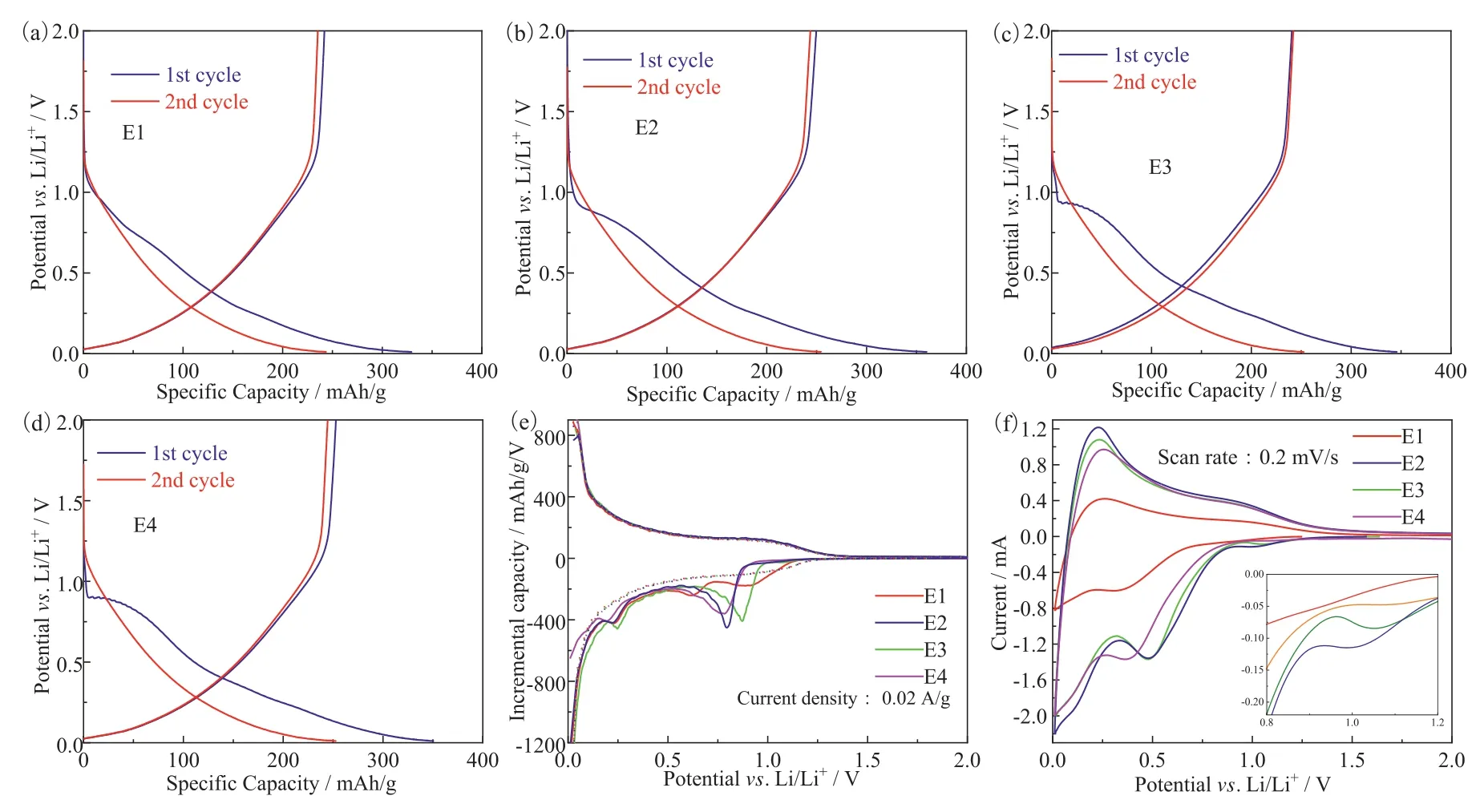
Fig.1.The first two cycle charge-discharge profiles of HC anode with different electrolytes at room temperature, (a) E1, (b) E2, (c) E3, (d) E4, (e) the differential capacity curves and (f) cyclic voltammetry curves.
In order to analyze the specific action process of additives during the first charging process, we obtained the differential capacity curve as shown in Fig.1e.It is believed that the peak in the curve represents a specific electrochemical reaction [22].In Fig.1e, the solid line represents the first cycle and the dotted line represents the second cycle.It can be seen that peaks only appear in the first cycle, and the potentials of the peaks corresponding to different electrolytes are also different, except for the peaks near 0.25 V.When no additives are used, the curve has two smaller peaks at about 0.65 and 0.85 V.With the addition of additives, there are larger peaks at about 0.79, 0.87 and 0.76 V, corresponding to the three additives respectively.The reaction potentials of VC, FEC and DTD are about 0.80 V, 0.90 and 1.05 Vvs.Li/Li+, and the results of VC and FEC are relatively consistent with those in literature [14].The possible reason for the inconsistency between the reaction potentials of DTD and those in the literature [14] is that graphite is used as anode in the literature, and there are differences between graphite and hard carbon in structure and main operating potential range.It can also be seen from Fig.1 that when the voltage is greater than 1.0 V, hard carbon has little capacity.Fig.1f shows the cyclic voltammetry curves of HC anode with different electrolytes with the scan rate of 0.2 mV/s.The reason why the peaks in the CV curve are inconsistent with those in the differential capacity curve may be that the scan rate used in the CV test is not small enough.
Fig.2 shows the rate performance of HC anodes using different electrolytes at different temperatures.After using the electrolyte containing additives, the rate performance of HC is improved compared with the electrolyte without additives.Among them, FEC exhibits the best rate performance at different temperatures, as shown in Figs.2a-d.It also has a certain low current discharge capacity even at –40 °C where other additives have almost no capacities.It is worth noting that the effect of VC is better than that of DTD at room temperature, but with the decreasing of temperature, for example, when the test temperature is 0 °C, the effect of DTD is better than that of VC.FEC has the best effect at different temperatures, and VC and DTD show good effect at room temperature and low temperature, respectively.Figs.2e and f show the rate performance curves of HC anode using electrolyte containing different FEC ratios.It can be seen that the electrolyte containing FEC shows the best rate performance when the volume ratio of FEC is 5% at −20 °C, but it is still the best when the volume ratio is 2%at −40 °C
As mentioned earlier, it is the increasing impedance of HC anode that mainly leads to the degradation of LIC performance at low temperature.Except that the solid diffusion impedance is related to the intrinsic properties of the anode material, other impedances that may lead to the increase of the anode polarization at low temperature are all related to the electrolyte.Specifically,Rsis related to the diffusion of the solvated Li+in the bulk electrolyte [23].RCTrepresents the impedance of the stripping of the solvated layer of Li+, andRSEIrepresents the impedance of the bare Li+diffusion through the SEI.In order to analyze the change of impedance at low temperature, we measured the EIS with three electrodes coin cell.
Fig.3 shows the EIS curves of HC anode with a voltage of 0.4 V at different temperatures.Before the EIS test, the cells were charged and discharged 5 cycles with a small current density, and then charged until the potential of HC versus the reference electrode reached 0.4 V, these operations were carried out at room temperature.The impedance of HC increases rapidly with the decrease of test temperature.Moreover, the trend of the first semicircle getting larger with the decrease of temperature is small, while the second semicircle becomes large rapidly with the decrease of temperature.Tables S2 and S3 (Supporting information) show the SEI impedance andRCTdata of HC anode at 0.4 V at different temperatures fitted by Fig.3.
The use of additives can slow down the increasing trend of impedance, but the influences are different.Among them, cells using electrolyte containing FEC show low impedance within the test temperature range, while VC and DTD show low impedance at room temperature and low temperature, respectively.We use the equivalent circuit model shown in Fig.3a to fit the EIS curve in Fig.3.TheRSEIandRCTobtained by fitting are then brought into Arrhenius formula as listed in Eq.1, to obtain the activation energy of the processes corresponding to the two impedances.

The fitting results are shown in Fig.4, in which Figs.4a and b correspond to the curves fitted byRSEIandRCT, respectively.For the process of Li+passing through SEI corresponding toRSEI, the activation energies of the four electrolytes are 7.65, 30.26, 22.36 and 20.45 kJ/mol, respectively.And for the charge transfer process corresponding toRCT, the activation energies of the four electrolytes are 66.18, 63.19, 52.12 and 56.29 kJ/mol, respectively.It indicates that the activation energy ofRCTis about twice that ofRSEI.The reason why the activation energy ofRSEIof E1 is significantly lower than that of the other three electrolytes may be that theRSEIof E1 is relatively large at 25 °C.With the decrease of temperature,the increase ofRSEIis small, resulting in the slope of the corresponding curve of E1 in Fig.4a being significantly lower than that of the other three electrolytes.It can also be seen from the activation energy data that theRCTaccounts for a larger part in the overall impedance.

Fig.2.The rate performance curves of hard carbon anode at different temperatures: (a) 25 °C, (b) 0 °C, (c) −20 °C, (d) −40 °C.The rate performance curves of HC anode using electrolyte containing different FEC ratios at different temperatures: (e) −20 °C, (f) −40 °C.

Fig.3.EIS curves of hard carbon at 0.4 V measured by three electrodes at different temperatures: (a) 25 °C, (b) 15 °C, (c) 5 °C, (d) −5 °C, (e) −15 °C, (f) −25 °C.
Fig.S3 (Supporting information) shows the relationship between the impedance and the voltage of HC, measured by the three electrodes coin cell during the first charge and discharge process at room temperature.As shown in Figs.S3a, c, e and g, although the electrolytes are different, the variation trend of impedance with voltage of HC is basically the same during the first charging process.When it is charged to 0.9 or 0.8 V, the change of impedance is small, and the impedance is basically maintained at a very high level.When it is charged to 0.6 V, the impedance decreases significantly compared with that at higher potential.Further, when it is charged to 0.4 V, the impedance decreases significantly again.Finally, the impedance decreases further with the decrease of potential and reaches the minimum at 0.01 V.In general,the impedance of HC during the first charging process can be divided into three levels.It is a high level from open circuit state to 0.8 V, a medium level from 0.8 V to about 0.4 V, and a low level from 0.4 V to 0.01 V.According to the change of impedance,we can divide the first charging process into four stages.The process from open circuit voltage to 0.8 V is the first stage, and the impedance may be reduced due to the use of specific additives,such as VC and DTD, but it is still at a high level on the whole, as shown in Figs.S3c and g, respectively.The second stage from 0.8 V to about 0.6 V, corresponds to the process of impedance changing from high level to medium level.The third stage is from about 0.6 V to 0.4 V, which corresponds to the process of impedance changing from medium level to low level, and the fourth stage is from 0.4 V to 0.01 V, which corresponds to the process of impedance further reduction on the basis of 0.4 V.
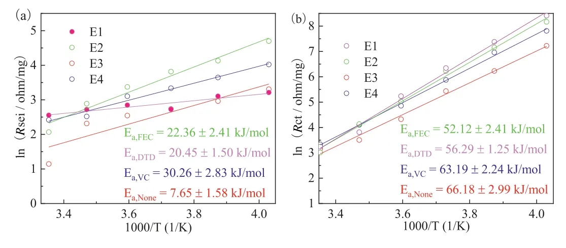
Fig.4.The curves fitted by Arrhenius formula, (a) and (b) correspond to the curves fitted by RSEI and RCT, respectively.
Figs.S3b, d, f and h show the change of impedance with voltage of HC during the first discharge process.It can be found that the impedance during discharge is maintained at a low level compared with the impedance under the same potential during charging.The change of impedance with potential during discharge is mainly caused by the second semicircle, and the change of the first semicircle is very small.The former corresponds to the impedance of de-solvation process, and the later corresponds to the impedance of SEI film.It indicates that the formation of SEI mainly occurs during the first charging process, and the impedance of SEI changes little during the first discharging process.By analyzing the data of potential corresponding to the reaction of different additives in the first charging process, it can be found that when the reaction considered to be related to the formation of SEI occurs at a specific voltage, the change of impedance of HC is relatively small.It can be speculated that additives may react and participate in the formation of SEI in one or more stages, but the reactions of additives at specific potentials may have a relatively small impact on the impedance of the cell or the SEI film.The growth of SEI is mainly a continuous process in the full voltage range.
Figs.3 and 4 show that the charge transfer process mainly affects the performance of HC at low temperature, and the improvement of performance at low temperature after using additives is mainly reflected in their influence onRCT.In order to further illustrate the influence of additives on the charge transfer process, the same method was used as reference [24] to test and obtain the Tafel curve at different temperatures, and fitted the corresponding exchange current density, which can be used to describe the ability of an electrode reaction to gain and lose electrons, and can reflect the difficulty of an electrode reaction, specifically, the greater its value, the faster the charge transfer process.As shown in Fig.S4 (Supporting information), the corresponding exchange current density also decreases with the decrease of temperature, indicating that the charge transfer process becomes slower with the temperature decreases.Specific additives (for example, FEC and DTD) can improve the exchange current density at low temperature, indicating that they can improve the charge transfer process.
In this work, we compared the effects of three additives (VC,FEC and DTD), on the rate performance of HC anode at −20 °C and −40 °C.We find that among them, FEC has the most obvious effect which shows the best rate performance at different temperatures, and has a certain discharge ability even at –40 °C.While VC and DTD show good rate performance at room temperature and low temperature, respectively.And the electrolyte containing 5% FEC shows the best rate performance at −20 °C while the electrolyte containing 2% FEC performs best when the test temperature was −40 °C.According to the change of impedance with potential during formation, we speculate that additives may react and participate in the formation of SEI, but the reaction of additives may have a relatively small impact on the impedance of the cell and the SEI film.Finally, the EIS test and fitting results show that the effect of additives on HC impedance at low temperature may be mainly reflected in its effect on charge transfer process.
Declaration of competing interest
The authors declare that they have no known competing financial interests or personal relationships that could have appeared to influence the work reported in this paper.
Acknowledgements
This work was supported by the National Natural Science Foundation of China (No.51777140), and the Fundamental Research Funds for the Central Universities at Tongji University (No.22120210173).
Supplementary materials
Supplementary material associated with this article can be found, in the online version, at doi:10.1016/j.cclet.2021.11.062.
 Chinese Chemical Letters2022年8期
- Chinese Chemical Letters的其它文章
- Adsorptive removal of PPCPs from aqueous solution using carbon-based composites: A review
- A review on hollow fiber membrane module towards high separation efficiency: Process modeling in fouling perspective
- Recent advances in DNA glycosylase assays
- Chiral pillar[n]arenes: Conformation inversion, material preparation and applications
- Recent progress in carbon-based materials boosting electrochemical water splitting
- Working principle and application of photocatalytic optical fibers for the degradation and conversion of gaseous pollutants