
Preparation of electrically enhanced forward osmosis (FO) membrane by two-dimensional MXenes for organic fouling mitigation
2022-09-16 05:24MengsiXuPinZhoChuyngTngXiwenYiXinhuWng
Chinese Chemical Letters 2022年8期
Mengsi Xu, Pin Zho,∗, Chuyng Y.Tng, Xiwen Yi, Xinhu Wng,c,∗
a Jiangsu Key Laboratory of Anaerobic Biotechnology, School of Environmental and Civil Engineering, Jiangnan University, Wuxi 214122, China
b Department of Civil Engineering, The University of Hong Kong, Hong Kong, China
c Jiangsu Collaborative Innovation Center of Technology and Material of Water Treatment, Suzhou University of Science and Technology, Suzhou 214122,China
ABSTRACT In this work, a conductive thin film composite forward osmosis (TFC-FO) membrane was firstly prepared via vacuum filtering MXenes nanolayer on the outer surface of polyethersulfone membrane followed by interfacial polymerization in the other side.Moreover, its feasibility of mitigating organic fouling under electric field was evaluated.Results indicated that the addition of MXenes greatly reduced the electric resistance of membrane from 2.1×10¹² Ω to 46.8 Ω, enhanced the membrane porosity and promoted the membrane performance in terms of the ratio of water flux to reverse salt flux.The modified TFC-FO membrane presented the optimal performance with 0.47 g/m2 loading amount of MXenes.Organic fouling experiments using sodium alginate (SA) and bovine serum albumin (BSA) as representative demonstrated that the introduction of MXenes could effectively enhance the anti-fouling ability of TFC-FO membrane under the electric field of 2 V.The interelectron repulsion hindered organic foulants attaching into membrane surface and thus effectively alleviated the membrane fouling.More importantly, the modified TFCFO membrane showed good stability during the fouling experiment of 10 h.In all, our work proved that introducing MXenes into the porous layer of support is feasible to alleviate organic fouling of FO membrane.
Keywords:Forward osmosis Conductive membrane MXenes Organic fouling Antifouling property
As an advanced membrane separation process, forward osmosis(FO) is driven by an osmotic pressure difference, through which water diffuses from an impaired feed stream into a concentrated draw solution across a dense semipermeable membrane [1–3].Attributed to low potential of membrane fouling and low energy consumption in certain applications, FO process demonstrates high popularity in the treatment of the heavily polluted wastewater characterized by high salinity and high content of refractory organic matters, such as reverse osmosis concentrate, landfill leachate and nutritious sludge [4–7].However, high concentration of organic contaminants is bound to cause sever membrane fouling, which would deteriorate membrane performance and ultimately shorten membrane life.Therefore, it is of great significance to mitigate organic fouling for the efficient application of FO technology [8–10].
Membrane properties play a vital role in the formation of organic fouling.It has been proven that organic fouling would be relieved by improving hydrophilicity, reducing roughness, or controlling charge distribution of membrane surface [11,12].However,the development of membrane surface modification suffered from some hinderances, such as the formed dense coating would reduce the water permeability; the main chemical structure of active layer would change, resulting in reduced stability and salt rejection; and the modification process is kind of cumbersome [8,11,12].As one of the effective approaches to control membrane fouling,the application of conductive membrane draws more and more concern at the last decades [13–15].For instance, Zhao and his co-workers [16] prepared a conductive PVDF-GO-Ni composite ultrafiltration membrane, which produced an enhanced anti-fouling capacity and high rejection of Congo red under an external electric field.In Wang’s work [17], an electrically conductive polyaniline reverse osmosis membrane was synthesized and presented low fouling potential by bovine serum albumin (BSA).Furthermore,Liuet al.[9] proposed a facile method to embed a continuous carbon nanotube electrode in FO membrane, which had a good resistance to organic and microbial fouling as the cathode of an electrochemical cell.Therefore, conductive membranes offer opportunities for greatly improved membrane antifouling capacity [18,19].However, most of current conductive modified membrane suffered from poor stability, low permeation and rejection.It is worthy to explore novel material to obtain high-quality conductive membrane.
As a novel layered nanomaterial firstly reported by Naguibet al.in 2011 [20], MXenes is a kind of two-dimensional transition metal carbide, which displays plenty of advantages, such as hydrophilic surface, excellent chemical stability and excellent electrical conductivity [21].There have been many studies of MXenes based membrane modification in aim to enhance permeability [22], rejection [23], or antifouling capacity [24].For instance, Liuet al.[25] reported a novel composite membrane based on graphene oxide and MXenes, and proved that the unique heterogeneous structure endowed the composite membrane with high rejection and permeability.Tanet al.[26] prepared a MXenes-coated polyvinylidene fluoride membrane to improve direct contact membrane distillation performance, and found that the introduction of MXenes could maintain high water flux and reduce energy consumption.Moreover, Wuet al.fabricated a MXenes interlayered polyamide(PA) FO membrane through brush-coating of MXenes on nylon base[27].Compared with virgin membranes, the resulting membrane had improved water/organic solvent permeability and low specific salt flux at the same time.Due to the excellent electrical conductivity, MXenes show a great potential for the conductive membrane modification.Moreover, compared with the conductive onedimensional nanomaterial CNTs, MXenes have a two-dimensional structure with atomic thickness and micrometer lateral dimensions, which have more contact area and would interact firmer with the supporter than CNTs [28].However, there are still limited works about MXenes based conductive membrane until now[29,30].Furthermore, most of the current modification methods containing surface coating, substrate blending and the introduction of interlayer might reduce the membrane stability [31].It is very necessary to develop a novel method to obtain the conductive membrane with fair stability.
In this case, a novel method was applied to fabricate a conductive thin film composite (TFC) membrane by vacuum filtering of ultra-thin MXenes onto a porous polyethersulfone (PES) support followed by an interfacial polymerization (IP) reaction.MXenes nanolayer and PA layer are placed in different sides of the PES substrate, which ensures the stability of modified membrane.The influence of MXenes on the membrane performance and stability was studied during the long-term fouling experiment of FO process.The modified TFC-FO membrane exhibited an efficient antifouling capacity and good stability.To the best of our knowledge,there is no research on the preparation of a conductive FO membrane with introduced MXenes layer into the porous support layer of substrate so far.
Plate PES microfiltration membrane (pore size, 0.22 μm) was provided by Yibo Co., Ltd., China.MXenes (Ti3C2Tx) was obtained from 11 Technology Co., Ltd., China.More properties about MXenes are presented in S1 (Supporting information).1,3,5-Benzenetricarbonyl trichloride (TMC, 98%) andmphenylenediamine (MPD, 99%) were supplied by Sigma-Aldrich Co.,Ltd., America.Sodium chloride (99.5%), sodium alginate (SA), BSA andn-hexane were obtained from Sinopharm Chemical Reagent Co., Ltd., China.
The dispersion of Ti3C2Txwas prepared by the following steps.Firstly, certain amounts (0, 5, 15, 25 and 35 mg) of Ti3C2Txwere added in 100 mL deionized (DI) water, and the suspension was subject to probe-sonication at 210 W for 0.6 h.To remove the unexfoliated bulks, the suspension was centrifuged (Thermo Fisher,Sorvall ST16R, America) at 4000 rpm for 0.2 h.Finally, the retained supernatants were vacuum-filtrated onto the outer surface of plate PES supports (Fig.1), resulting in Ti3C2Txloading of 0.18±0.01,0.47±0.06, 0.75±0.09 and 1.09±0.06 g/m2, respectively (based on gravimetric analysis).After vacuum-filtration, the Ti3C2Tx-coated PES membrane was spliced at 60°C for 15 min.The resultant films were soaked in pure water at 4°C for further testing.

Fig.1.Illustration of membrane fabrication process, (A) TFC-C membrane and (B)TFC-M membrane.
The selective layer of PA was synthesized on PES membraneviaIP reaction of aqueous phase of MPD (3.4 wt%) and hexane phase of TMC (0.15 wt%) [32].PES and MXenes-PES membrane was taken from DI water carefully and then placed in a clean plate glass for air drying.When there were no obvious water drops on the surface, the targeted membrane was exposed to MPD aqueous phase.After 2 min, excess MPD solution was removed by rubber roller.Then, hexane phase of TMC solution was introduced and reacted for 1 min.Finally, the prepared membranes were transferred to DI water at 95°C and cured for 2 min.The control membrane(named as TFC-C membrane) and Ti3C2Tx-modified TFC-FO membrane (named as TFC-M-x membrane with x representing mass of Ti3C2Txused (5, 15, 25, and 35 mg)) was stored in DI water at 4°C for further use.
Field-emission scanning electron microscopy (FE-SEM) supplied by Hitachi (S4800) was used to analyze the structures and morphologies of fabricated membranes.Atomic force microscopy(AFM) from Bruker (Multimode 8, Germany) was applied to capture the membrane surface roughness and topography.Zeta potential of membrane surface was conducted (Anton Paar, Surpass 3,Austria), and surface resistance was obtained by a resistivity analyzer (JingGe, ST2253y, China).Moreover, membrane surface hydrophilicity was determined through a water contact angle (WCA)analyzer (Kruss, DSA100, Germany).Porosity was measured by a mercury porosimeter (Micromeritics, Autopore IV 9510, America).
Membrane performance was evaluated using a bench-scale FO unit containing a membrane coupon with an effective area of 0.0034 m2.The schematic layout is illustrated in S2 (Supporting information) with more details available in our earlier publication [9].Before the experiments, the membrane was pretreated by soaking in DI water at 25±2°C for 24 h.Membrane performance was tested using DI water and 4 mol/L NaCl as feed solution (FS) and draw solution (DS) at 0.1 L/min.Mass variation of FS was constantly monitored using a computer-controlled balance (Mettler Toledo, PL6001E).
SA and BSA were selected as model organic foulants to evaluate the fouling resistance of membranes on the same laboratory-scale FO setup.According to previous literature [8,33-35], their concentrations were chosen as 400 mg/L and 200 mg/L in current study,respectively.The fouling experiment was conducted for continuous 10 h with 4 mol/L NaCl as the DS and 4 mmol/L NaCl with the addition of 400 mg/L SA or 200 mg/L BSA as the FS, respectively.For the conductive FO membrane, the membrane fouling experiment was also operated with TFC-M-15 membrane as the cathode and titanium plate as the anode in the aid of electric field.Compared with 2 V, the role of 1 V was very limited and unobvious; while the voltage of 4 V would cause lots of energy consumption.The elec-tric field of 2 V could achieve good antifouling performance with a reasonable energy consumption.Therefore, all the fouling experiments were conducted under the electric field of 2 V in this work.Fouled membranes were carried out carefully from the FO reactor,and then stored at 4 °C for further analyses.
By measuring the absorbance of DS at the initial and end of the fouling experiment under a wavelength of 300 nm, it is possible to verify whether the MXenes material would leak during the fouling experiment.The morphological distribution of foulants on membrane surface was illustratedviaFE-SEM (Hitachi, S4800, Japan).Total organic carbon (TOC) analyzer (Shimadzu, TOC-Vcph, Japan)was used to determine the rejection of organic matter by the FO membrane.In addition, Calcofluor white and Fluorescein isothiocyanate were applied for staining
SA and BSA foulants, respectively.The distribution and abundance of SA and BSA foulants were analyzed by a laser confocal microscope (CLSM) (Zeiss, LSM 710, Germany).Three-dimensional image analysis software PHLIP and LASAFE are used to process CLSM images [36].
To investigate the influence of MXenes loading amount on membrane performance, the value ofJWandJSof the initial 1 h were measured during the permeate experiment based on the Eqs.1 and 2 of S3 (Supporting information).As illustrated in Table 1,the addition of MXenes generally enhanced the permeation while had little influence on the rejection.The selectivity of the FO membrane can be evaluated by the reciprocal of specific salt flux,i.e.,JW/JS, with a high value indicating better selectivity.Table 1 shows that the introduction of MXenes enhanced water flux and selectivity of TFC-FO membranes up to the optimal loading of 0.47 g/m2.However, further increase in MXenes loading led to lower FO water flux and selectivity.
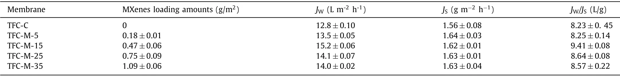
Table 1 Filtration performances of the TFC-FO membranes.a
Some basic properties of membrane, such as water permeability coefficient (A), solute permeability coefficient (B), structural parameter (S) and porosity were obtained according to Eqs.3–6 of S3 (Supporting information).As presented in Table S1 (Supporting information), the introduction of MXenes increased membrane porosity at first, and then caused it to decline.With the increase of MXenes, some pore spaces of membrane internal structure might be blocked (Fig.S3 in Supporting information), thus causing porosity decrease.Without MXenes introduced into the pore of PES support, PA layer would form partly inside the support pore.The resulting PA layer was thick and had more resistance of water permeation [27,37].On the other hand, the addition of MXenes would hinder the formation of PA layer inside the support layer, which promoted the water permeation.However, the pressure of water permeation also increased with the enhanced MXenes loading.Thus,Avalue increased firstly and then decreased with the introduction of MXenes.
Among all the modified membranes, TFC-M-15 membrane shows the lowestSvalues (911±28 μm), and represents the best performance in terms ofJWandJW/JS.Thus,this membrane was chosen for further characterization and anti-fouling performance research.
Details of the SEM, AFM and WCA information are shown in Fig.S4 (Supporting information).A classical continuous leaflike ridge-and-valley structures were observed from the PA surface of both TFC-C membrane and TFC-M-15 membrane (Figs.S4A and B in Supporting information), which was consistent with the existing literature reports [38–40].The surface AFM (Figs.S4C and D in Supporting information) of TFC-M-15 membrane(52.1±10.6 nm) had a similar roughness with that of TFC-C membrane (51.3±4.4 nm).As shown in WCA images, the surface contact angle of TFC-M-15 membrane (Fig.S4F in Supporting information)and TFC-C membrane (Fig.S4E in Supporting information) had no significant difference.In addition, both membrane surfaces were negatively charged under neutral pH conditions (−68.1 mV for the TFC-C membranevs.−70.2 mV for the TFC-M-15 membrane).The above results all showed that the addition of MXenes material into the support layer had no significant changes on the surface morphologies and properties of PA layer.
Considering the subsequent use of an external electric field to control organic fouling, the electric resistance of TFC-FO membrane was further analyzed by the four-point probe method [8].The electric resistance of TFC-C membrane was measured to be 2.1×10¹²Ω, while that of TFC-M-15 membrane was 46.8Ω.It indicated that the existence of MXenes greatly reduced the FO membrane electric resistance, which enables subsequent application of electric field.Furthermore, the leakage of MXenes was determined by measuring the absorbance of DS at the initial and end of the fouling experiment under a wavelength of 300 nm.The absorbance of DS had no change during the experiment, implying negligible leakage of MXenes.The stability of MXenes guaranteed the durability of modified TFC-FO membrane performance.
To evaluate the feasibility of mitigating organic fouling of TFCM-15 membrane, SA and BSA were selected to be the simulated foulants.Flux variation and membrane fouling behavior of the TFCFO membrane with and without an electric field were investigated.As described in Fig.2a, under the condition of no electric field,the water flux of TFC-C and TFC-M-15 membranes declined by 40.4% and 38.3% during the SA fouling experiment.It indicated that the anti-fouling performance of these two membranes had no big difference without electric field.On the other hand, the TFC-M-15 membrane showed higher flux and slower flux decline (32.5%)than the TFC-C membrane under a 2 V electric field.Introduction of electric field greatly improved the anti-fouling performance of the TFC-M-15 membrane.The situation of BSA fouling experiment had the similar variation tendency with SA fouling.As illustrated in Fig.2b, the water flux reduced by 12.6%, 8.2% and 4.5% to TFC-C,TFC-M-15 membrane without and with an electric field.
Characteristics of SEM and CLSM were conducted to analyze the condition of membrane fouling.As depicted in Fig.3, plenty of SA foulants adsorbed and gathered on the surface of both TFC-C and TFC-M-15 membranes without an electric field; while the amounts of absorbed SA foulants decreased when the electric field was applied.Moreover, the amount of SA deposited on the membrane surface was further calculatedviathe software PHLIP.When the electric field was applied, the amount of SA deposited on the TFCM membrane surface was 0.70 μm3/μm2, while that of the TFC-C membrane was 4.85 μm3/μm2.It implied that the electric field can greatly reduce the deposition of SA foulants on the surface of TFCM-15 membrane.More description about BSA fouling is presented in S7 (Supporting information).
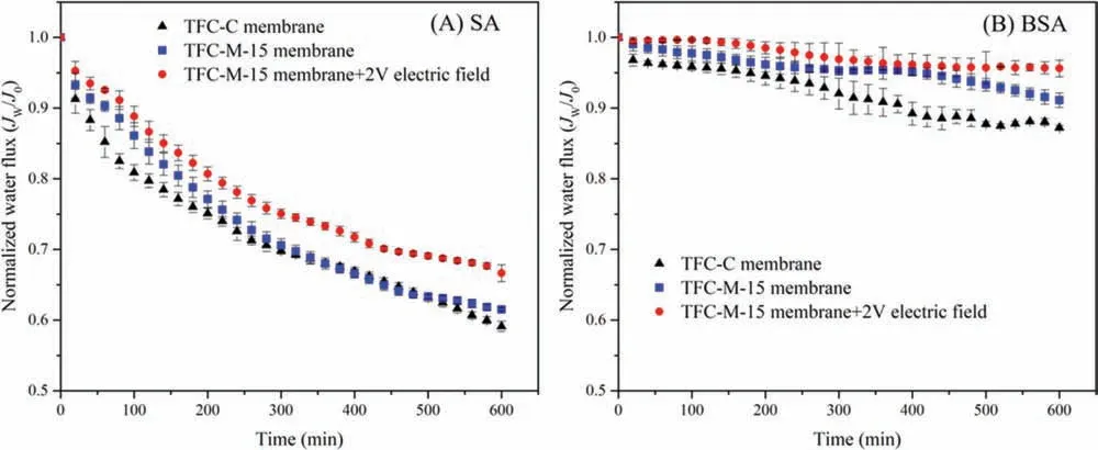
Fig.2.Variation of representative water flux of (A) SA and (B) BSA fouling experiments.FO fouling filtration was conducted with feed solution containing 400 mg/L SA or 200 mg/L BSA and 4 mmol/L NaCl for 10 h at 25±2 °C and 0.1 L/min.
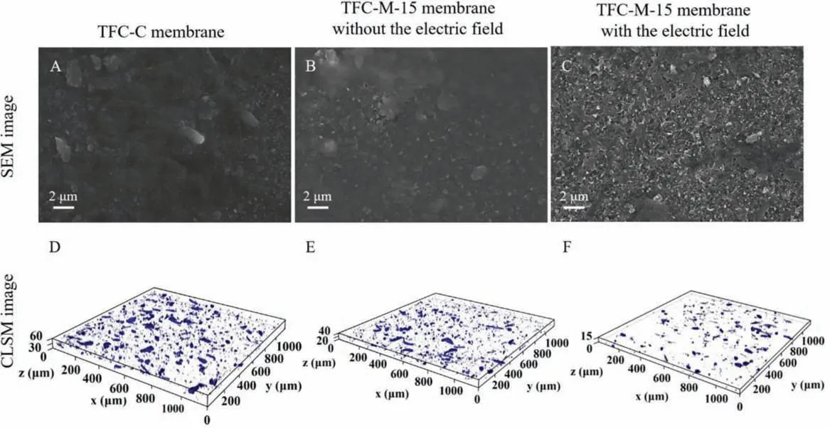
Fig.3.SEM images (A-C) and CLSM images (D-F) of surface fouling of the TFC-C membrane and TFC-M-15 membrane without the electric field, and the TFC-M-15 membrane with the electric field during SA fouling filtration.
Results of the fouling experiments showed that the introduction of MXenes in the support layer of membrane increased water permeation and promoted the fouling resistance slightly under the condition of no electric field.While the promotion of fouling resistance was enhanced widely in the aid of electric field.It demonstrated that the introduction of the MXenes layer had an elevating effect on alleviating organic fouling by optimizing membrane structure with a smallerSvalue; however, this influence was very limited owing to no impacts on surface morphologies, roughness and hydrophilicity of TFC-FO membrane.Introduction of electric field enhanced the anti-fouling capacity of TFC-M-15 membrane.It could be attributed to the electrostatic repulsion between the negatively charged foulants and TFC-M-15 membrane, which had also been reported by a previous literature [41].The electrostatic repulsion reduced the attachment of foulants into the membrane surface, and then alleviated the organic fouling [8,19].Moreover,the role of electrode reaction at cathode in affecting the membrane fouling can be neglected owing to the low amount of oxygen below the limit of detection.In this case, the electric field force was the main reason for the TFC-M-15 membrane to alleviate membrane fouling.The schematic diagram of anti-organic fouling mechanism was presented in Fig.4.Under the condition of no electric field,the amounts of organic foulants on the surface of TFC-M-15 membrane were slightly reduced compared with that of TFC-C membrane.After the electric field was applied, the amounts of foulants on TFC-M-15 membrane surface were significantly decreased due to the electrostatic repulsion [41,42].
In this work, a conductive TFC-FO membrane was preparedviavacuum filtering MXenes dispersion on the back of the PES membrane, and the feasibility of conductive FO membrane in alleviating organic fouling was investigated under the condition of an external electric field.The results proved that introduction of MXenes would effectively promote the permeation performance of TFC-FO membrane.The addition of MXenes enhanced the membrane porosity and reduced membrane electric resistance without influencing the morphologies and chemical properties of the membrane.In addition, fouling experiments of both SA and BSA fouling presented that introduction of MXenes enhanced the anti-fouling ability of membrane under the electric field.Under the condition of an external electric field, the negatively charged TFC-M-15 membrane excluded organic foulants and prevented their attachment into the membrane surface, thereby effectively alleviating organic fouling.Furthermore, the leakage of MXenes was undetectable.The negative leakage manifested that the modification is stable and feasible.In all, our work provides some inspiration in the field of desirable support design for TFC-FO membranes preparation with high permeation and low potential of membrane fouling.
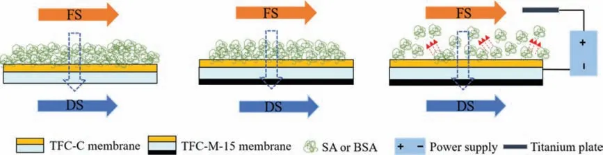
Fig.4.Schematic diagram of anti-organic fouling mechanism of the TFC-FO membrane.
Declaration of competing interest
The authors declare that there are no completing interests.
Acknowledgments
This work was supported by the National Natural Science Foundation of China (No.51978312), the Six Major Talent Peaks of Jiangsu Province (No.2018-JNHB-014), and the Program to Cultivate Middle-aged and Young Science Leaders of Colleges and Universities of Jiangsu Province.
Supplementary materials
Supplementary material associated with this article can be found, in the online version, at doi:10.1016/j.cclet.2021.11.071.
 Chinese Chemical Letters2022年8期
- Chinese Chemical Letters的其它文章
- Adsorptive removal of PPCPs from aqueous solution using carbon-based composites: A review
- A review on hollow fiber membrane module towards high separation efficiency: Process modeling in fouling perspective
- Recent advances in DNA glycosylase assays
- Chiral pillar[n]arenes: Conformation inversion, material preparation and applications
- Recent progress in carbon-based materials boosting electrochemical water splitting
- Working principle and application of photocatalytic optical fibers for the degradation and conversion of gaseous pollutants