
In situ conversion builds MIL-101@NiFe-LDH heterojunction structures to enhance the oxygen evolution reaction
2022-09-16 05:24JingweiHungKiLiLeiWngHoudeSheQizhoWng
Chinese Chemical Letters 2022年8期
Jingwei Hung, Ki Li, Lei Wng, Houde She, Qizho Wng,b,c,∗
a College of Chemistry and Chemical Engineering, Gansu International Scientific and Technological Cooperation Base of Water-Retention Chemical Functional Materials, Northwest Normal University, Lanzhou 730070, China
b School of Environmental Science and Engineering, Chang’an University, Xi’an 710054, China
c Tianjin Key Laboratory of Building Green Functional Materials, Tianjin Chengjian University, Tianjin 300384, China
ABSTRACT The construction of rich phase interfaces to increase active reaction area in hybrid materials is an excellent strategy to improve electrochemical performance.Under this guideline, MIL-101@OX-metal organic framework (MOF) is constructed by the "MOF on MOF" method, then converts to MIL-101@NiFe-layered double hydroxides (LDH) by in situ transformation in alkaline solution.MIL-101@NiFe-LDH shows excellent electrochemical water oxidation performance.It needs only an overpotential of 215 mV to drive 10 mA/cm2 of oxygen evolution reaction (OER), which is less than that of NiFe-LDH, MIL-101.In addition,MIL-101@NiFe-LDH has the smallest Tafel slope (55.1 mV/dec) compared with NiFe-LDH (61.1 mV/dec),MIL-101 (150.8 mV/dec).The excellent water oxidation activity is due to the high phase interfaces derived from high specific surface area of MOF.This work offers an alternative method for making MOF/LDH heterostructures with an optimized phase interfaces and provides new insights for OER.
Keywords:Mil-101@NiFe-LDH OER Electrocatalysis Alkalize
With the massive use of traditional fossil fuels, global warming and carbon emissions are becoming a pressing issue for mankind [1–3].A growing number of researchers are moving toward hydrogen-powered technologies as highly efficient and clean replacements for fossil fuels.Among many innovative methods for hydrogen production, water electrolysis has received much attention due to its simplicity, high purity and mature technology than microbial and photolysis methods [4,5].Oxygen evolution reaction(OER) [6–8] is a difficult process in water splitting because it undergoes a 4-electron transfer process, which leads to a high overpotential [9,10].Although many OER catalysts with high performances have been designed, driving OER with high efficiency at low overpotential still seems to be a challenge.Advanced catalysts for OER are generally noble metal oxides and their derivates, but their high cost impedes their further commercial large-scale applications [11].To settle this problem, sulfides [12–15], phosphides[16], layered double hydroxides (LDH) [17]etc.have been widely researched to replace OER noble metal based catalysts.
Metal organic frameworks (MOFs) [18–21] have attracted wide attention because of their large surface area, adjustable morphology and permanent structure, which may offer numerous surfaceactive sites for efficient water oxidation [22–25].However, majority of their metal active sites are hidden very deeply in the MOF frames and may not be utilized to catalyze the reactions.In addition, the poor stability and conductivity of MOFs are important issues that must be overcome in electrocatalyst applications, particularly under alkaline/acidic conditions.For these reasons, Kenet al.propose an “MOF on MOF” concept to solve these problems and which is proved to be effective [24].Zhaiet al.introduce anin situsemi-conversion method to turn FeNi-MOF-74 into FeNi-LDH,which exhibited excellent OER performance [26].Yanget al.discover that oxalate MOF (OX-MOF) could be converted into NiFe-LDH in alkaline solution and preserves its shape, showing excellent catalytic performance for OER [27].Based on the above design concept and results, we try to combine the “MOF on MOF” concept within situconversion method to make an OER electrocatalyst with excellent performance.
Here, MIL-101@NiFe-LDH heterostructure is designed and synthesized by growing two MOFs (MIL-101 and OX-MOF) successively on nickel foam (NF) substrate followed byin situconversion of OX-MOF to NiFe-LDH.The NiFe-LDH heterostructures constructed by this method have inherited not only large-scale surface area of MOF, but also superior phase interface.To be expected, the MIL-101@NiFe-LDH heterostructure shows excellent OER performance.
Typicalin situsynthesis route of MIL-101@NiFe-LDH is schematically illustrated in Scheme 1.Before experiment, NF (3 × 1 cm2,Kunshan Guangjiayuan New Materials Co., Ltd.) substrates were ultrasonically cleaned for 30 min in 1 mol/L of hydrochloric acid solution, ethanol and distilled water, respectively.Then dry them in an oven at 60 °C overnight.The synthesis of MIL-101@NiFe-LDH on NF consists of the following three steps: (1) Synthesis of MIL-101 on NF.Put a piece of NF into an autoclave with teflon lining, then add a mixed solution of 1.5 mmol terephthalic acid (AR, Shanghai Macklin Biochemical Co., Ltd.), 2.5 mmolferric chloride hexahydrate (AR, Shanghai Macklin Biochemical Co., Ltd.) and 15 mLN,N-dimethylformamide (DMF) into it.The autoclave was put into an oven to react at 110 °C for 20 h.After the reaction, the product was washed with ethanol and distilled and dried in an oven at 60 °C.(2) Synthesis of MIL-101@OX-MOF on NF.Put 0.15 mmol(73.6 mg) potassium trioxalatoferrate(III) trihydrate (AR, Shanghai Macklin Biochemical Co., Ltd.), 0.15 mmol (35.5 mg) nickel chloride hexahydrate (AR, Sigma-Aldrich) and 0.15 mmol (55.6 mg)tetrapentylammonium bromide (AR, Shanghai Macklin Biochemical Co., Ltd.) into 3 mL distilled water.After stirring for 20 min, then put the above made MIL-101 into the solution and leave it to react for 75 min.After the reaction, wash it with ethanol and put it into an oven at 75 °C overnight.(3) Synthesis of MIL-101@NiFe-LDH on NF.Take a piece of the prepared MIL-101@OX-MOF into 6 mL distilled water, leave it for 5 min to get good wettability.Then, add 15 mL 1 mol/L potassium hydroxide (KOH) solution into the above aqueous solution slowly drop by drop and keep it actionless for 45 min to make MIL-101@OX-MOF fully convert into MIL-101@NiFe-LDH.Finally, take the obtained MIL-101@NiFe-LDH out, wash it with ethanol and distilled water, and dry it at 60 °C for 4 h.
X-ray diffraction (XRD) data are obtained on a Bruker D8 Advance diffractometer with a Cu Kαradiation source.The X-ray photoelectron spectroscopy (XPS) analysis is carried out on a Thermo ESCALAB 250XI photoelectron spectrometer.Data for all samples are calibrated with C 1s (284.8 eV).The scanning electron microscope (SEM) images and transmission electron microscopy (TEM)images are recorded on a FEI Helios G4CX SEM and a FEI Talos F200S transmission electron microscope.Fourier transform infrared spectra (FTIR) test is performed on a Nicolet iS50 spectrometer.
The electrochemical properties of the prepared materials were evaluated on a CHI 760E workstation using a three-electrode system.NF supported material (3 × 1 cm2) was used as working electrode, 1 × 1 cm2of NF supported material was immersed into the electrolyte.Hg/HgO electrode and Pt sheet were used as a reference electrode and a counter electrode, respectively.Linear sweep voltammetry (LSV) curve was obtained at a slow scan rate (1 mV/s)in 1 mol/L KOH.The Tafel slope is obtained from the LSV curve by the equation (η=a+blogj, whereηis overpotential, it is calculated as following:η=ERHE−1.23 V,ais a constant,bis the Tafel slope andjis the current density).The stability test was performed for 24 h at a voltage value corresponding to 10 mA of the LSV curve.
From Figs.1A and B, it can be found that NF is smooth on the surface.After growing MIL-101, the smooth surface is covered in full of nanoparticles (Figs.1C and D), indicating the successful preparation of the MIL-101.As shown in Figs.1E and F, columnar OX-MOFs are overlaid on MIL-101.The design of "MOF on MOF"has been realized.The surface of MIL-101@OX-MOF becomes rough after alkalinization treatment (Figs.1G and H), indicating that MIL-101@OX-MOF has transformed into MIL-101@NiFe-LDH, in which the columnar form was retained.This could be confirmed by the control experiment of OX-MOF alkalinization treatment.It can be seen from Fig.S1 (Supporting information) that the surface of OXMOF becomes rough after KOH treatment, confirming the rough property of NiFe-LDH and successful conversion of MIL-101@OXMOF to MIL-101@NiFe-LDH.The 0.25 nm lattice spacing in Fig.1I corresponds to the (012) crystal plane of NiFe-LDH, and the obvious phase interface also indicates that MIL-101 and NiFe-LDH form a heterojunction [28].Mapped energy dispersive X-ray spectroscopy (EDS) elemental image of MIL-101@NiFe-LDH in Fig.S2(Supporting information) shows the uniform space distribution of C, O, Fe and Ni element.
XRD tests were used to confirm the material structure of the prepared electrodes.As exhibited in Fig.2A, MIL-101 shows diffraction peaks located at 5.9°, 8.4°, 9.0°, 10.4°, and 16.4°, which are consistent with the simulated data of MIL-101 [29].Among them,the diffraction peak at 9.0° is still can be observed in the MIL-101@NiFe-LDH composite sample, indicating that MIL-101 remains unchanged after KOH treating.The XRD patterns of OX-MOF and NiFe-LDH derived from OX-MOF by KOH treating are tested to prove the conversion of OX-MOF to NiFe-LDH.It can be seen from Fig.S3 (Supporting information) that part diffraction peaks of OXMOF correspond with the simulated data of OX-MOF.However, the diffraction peaks of OX-MOF change completely after treating with KOH solution.New diffraction peaks at 34.4°, 37.1° and 60.9° are corresponding to the (012), (015) and (113) crystallographic planes of LDH [30], which proves that OX-MOF can be successfully converted to LDH by KOH solution treating.Similarly, MIL-101@OXMOF shows entirely different diffraction peaks after KOH treating(Fig.2A).Diffraction peaks at 23.1° and 37.6° are corresponding to the (006) and (014) crystallographic planes of NiFe-LDH, proving MIL-101@NiFe-LDH can be converted from MIL-101@OX-MOF.Infrared (IR) spectrum of OX-MOF (Fig.2B) shows that the peaks at 2738 cm−1and 2921 cm−1are attributed to quaternary ammonium salt and CH2groups, and the MOF has the presence of Pen4N+.However, these signal peaks are absent in the IR of NiFe-LDH.IR signals at 1633 and 1348 cm−1in NiFe-LDH are attributed to the oxalate ions [27].
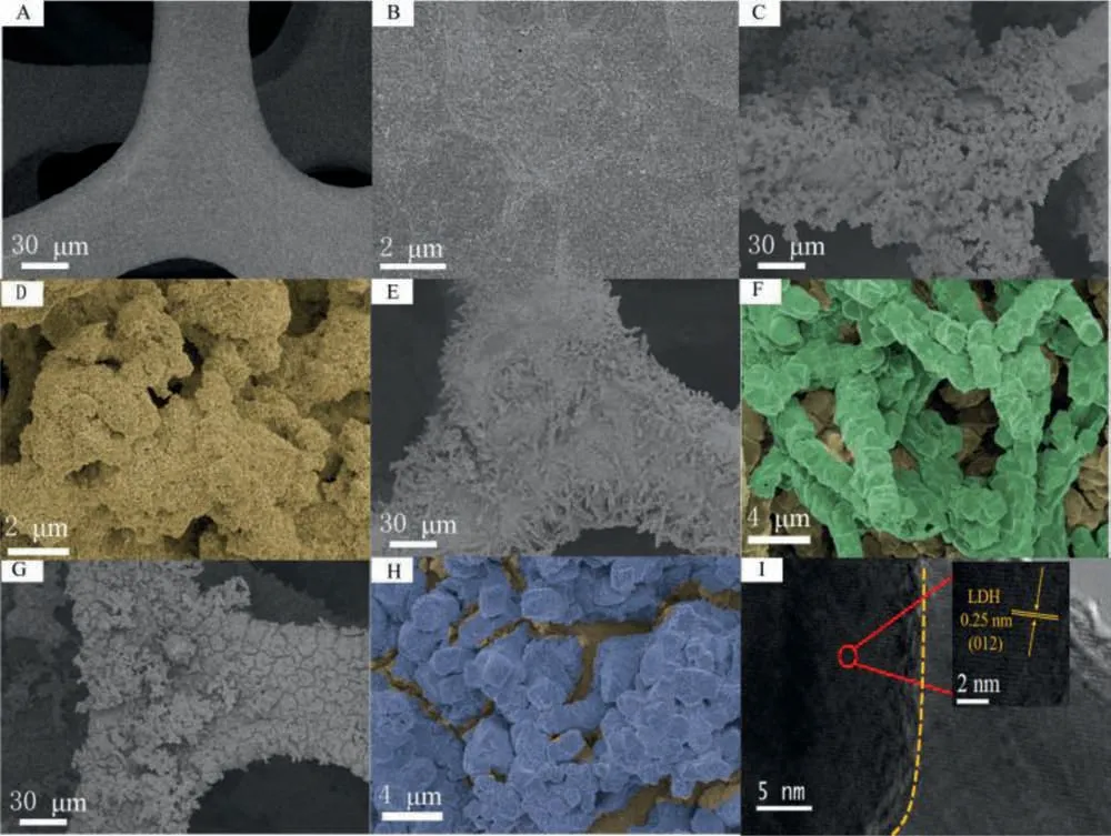
Fig.1.SEM images of NF (A, B), MIL-101 (C, D) and MIL-101@OX-MOF (E, F).SEM (G, H) and HR-TEM (I) images of MIL-101@NiFe-LDH.
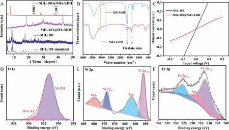
Fig.2.(A) XRD patterns of MIL-101@NiFe-LDH, MIL-101@OX-MOF, MIL-101 as well as simulated pattern of MIL-101.(B) IR patterns of OX-MOF and NiFe-LDH.(C) Input voltage-output current characteristic curves of MIL-101 and MIL-101@NiFe-LDH electrodes.The red dotted line is added as linear reference.(D-F) XPS spectra of O, Ni and Fe, respectively.
Input voltage-output current characteristic curves are tested to judge the formation of heterojunction between MIL-101 and NiFe-LDH.As demonstrated in Fig.2C, MIL-101 electrode shows a linear relationship between the output current and input voltage, indicating that the contact type between MIL-101 and NF substrate is ohmic contact.Conversely, there is a nonlinear relationship between the output current and input voltage of the MIL-101@NiFe-LDH electrode, indicating that the interface contact type between MIL-101 and NiFe-LDH is a non-ohmic contact.That is to say, MIL-101 and NiFe-LDH in the MIL-101@NiFe-LDH electrode are closely integrated to form heterojunction [31].
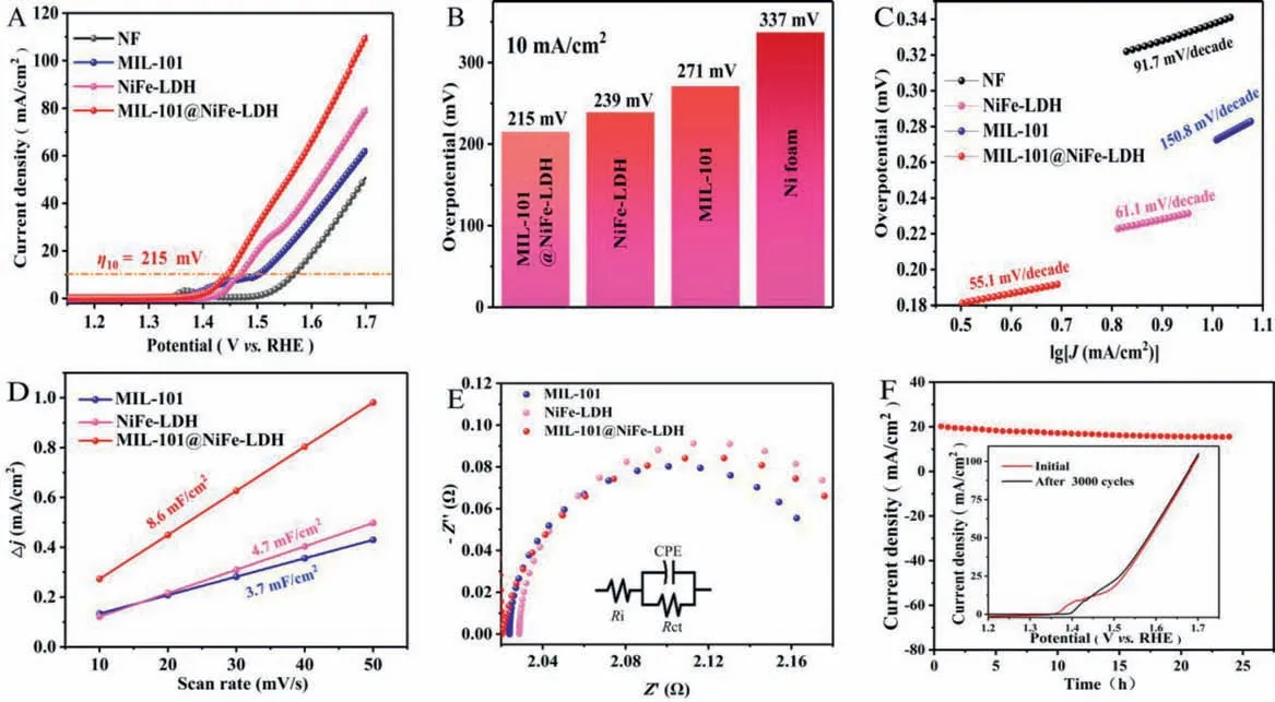
Fig.3.(A) LSV curves NF, MIL-101, NiFe-LDH, MIL-101@NiFe-LDH and their overpotentials at 10 mA/cm2 (B), Tafel plots (C).(D) Linear relationship between the capacitive current and scan rate.(E) Electrochemical impedance spectroscopy of various electrodes.The inset image is the simulative equivalent circuit.(F) I-t curve of MIL-101@NiFe-LDH.The inset image is the comparison of LSV curve before and after 3000 cycles test.
XPS spectra are measured to further analyze material composition.As shown in Fig.S4 (Supporting information), XPS survey spectrum shows that MIL-101@NiFe-LDH contains elements such as C, O, Fe and Ni.The O 1s spectrum of MIL-101@NiFe-LDH shows two peaks at 533.4 and 531.4 eV, which can be respectively assigned to the adsorbed water at the surface and hydroxide of the carboxylate ion (Fig.2D).As can be observed in the Ni 2p spectrum(Fig.2E), the signals of the two peaks at 873.8 and 856.1 eV are in agreement with 2p1/2and 2p3/2of Ni2+accompanied by satellite peaks (denoted as “Sat.”) [32].In Fig.2F, Fe 2p1/2and Fe 2p3/2peaks with the respective binding energies of 725.7 and 712.1 eV are characteristic of Fe3+in NiFe-LDH [33].
To compare OER activity of the catalysts, the alkali treating time was optimized firstly.It is found that the obtained NiFe-LDH with a treating time of 75 min has the best OER activity (Fig.S5 in Supporting information).Unless otherwise indicated, all the NiFe-LDH and MIL-101@NiFe-LDH is treated in alkali solution for 75 min.As shown in Fig.3A, NF has the biggest onset potential.MIL-101 and NiFe-LDH have slightly smaller onset potentials.MIL-101@NiFe-LDH composite electrode has the minimum onset potential of 1.4 V.This demonstrates that the strategy of combining MIL-101 and NiFe-LDH to achieve high OER activity is successful.The MIL-101@NiFe-LDH electrode only requires an overpotential of 215 mV to drive 10 mA/cm2of OER, which is less than that of NiFe-LDH (239 mV), MIL-101 (271 mV) and NF (337 mV) electrodes(Fig.3B).The results show that the OER activity of MIL-101@NiFe-LDH is superior to other advanced catalysts that have been reported (Table S1 in Supporting information).The results showed that MIL-101@NiFe-LDH has the highest catalytic activity, indicating that the rich phase interface of MIL-101@NiFe-LDH has a positive effect on the catalytic activity.In addition, MIL-101@NiFe-LDH has the smallest Tafel slope (55.1 mV/dec) compared with NiFe-LDH (61.1 mV/dec), MIL-101 (150.8 mV/dec) and NF (91.7 mV/dec),indicating quick surface kinetics of MIL-101@NiFe-LDH (Fig.3C).
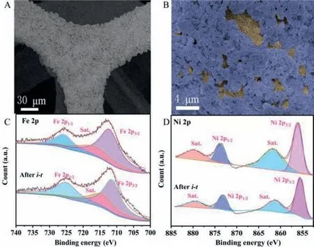
Fig.4.(A, B) SEM images of MIL-101@NiFe-LDH after i-t-test.(C-D) The XPS spectra of MIL-101@NiFe-LDH before and after i-t-test.
The true active reaction area of the OER catalyst is usually hardly measured precisely.Here, the electrochemical active surface area (ECSA), which is directly proportional with the electrochemical double layer capacitance (Cdl), is used to estimate active reaction area.Cyclic voltammetry experiments (1.125∼1.225 Vvs.RHE)were performed at different scan rates to obtainCdl(Fig.S6 in Supporting information).As can be seen from Fig.3D, theCdlvalue of MIL-101@NiFe-LDH (8.6 mF/cm2) is significantly larger than that of NiFe-LDH (4.7 mF/cm2) and MIL-101 (3.7 mF/cm2).This means that the MIL-101@NiFe-LDH heterostructure with double-layer structure provides a rich active reaction area for surface-catalyzed reactions,which partly explains the remarkably high-level activity of the MIL-101@NiFe-LDH heterostructure for OER.MIL-101 (Rct= 0.16Ω), NiFe-LDH (Rct= 0.18Ω) and MIL-101@NiFe-LDH (Rct= 0.17Ω) exhibit identical charge transfer resistance (Rct) (Fig.3E), pointing to the fact that these electrocatalysts have almost the same electron transfer behavior among electrolyte to electrode interface.That is, different OER performance of these electrodes does not origin from electron transfer character.As can be seen in Fig.3F, MIL-101@NiFe-LDH exhibits good stability during 24 h test at 1.47 Vvs.RHE.Also, the good stability of MIL-101@NiFe-LDH is illustrated by the fact that its OER activity performs as before after 3000 cycles(inset in Fig.3F).
As shown in Figs.4A and B, the overall appearance of MIL-101@NiFe-LDH is not changed after the stability test.It still keeps the double-layer structure, indicating excellent stability property of this electrode.It can be seen from the comparison of XPS spectra(Figs.4C and D) before and afteri-t-test that the binding energy of Fe 2p and Ni 2p basically keep unchanged.All these results prove the excellent stability of MIL-101@NiFe-LDH during long-time water splitting process.
In conclusion, MIL-101@NiFe-LDH is fabricated under the guideline of “MOF on MOF” concept and the following alkali treating.OX-MOF isin situsuccessfully converted to NiFe-LDH on MIL-101 to form MIL-101@NiFe-LDH by the treatment of KOH solution.MIL-101@NiFe-LDH shows an OER onset potential of 1.4 V and an overpotential of 215 mV to drive 10 mA/cm2of OER, which is less than that of NiFe-LDH, MIL-101 and NF.The excellent OER performance could be ascribed to rich phase interface in MIL-101@NiFe-LDH, which provides more active reaction area derived from the high specific surface area of MOF.Due to thein situgrowth,MIL-101@NiFe-LDH also exhibits good stability during long time OER test.This work provides a new strategy for constructing of MOF/LDH heterostructures, which can be applied to the construction of other catalyst materials possessing excellent electrochemical performance.
Declaration of competing interest
The authors declare no conflict of interest.
Acknowledgments
This work was financially supported by the National Natural Science Foundation of China (No.21808189), the National Natural Science Foundation of Gansu (No.20JR5RA523), and the Young Teachers’Research Ability Improvement Project of Northwest Normal University (NWNU-LKQN2020–01).
Supplementary materials
Supplementary material associated with this article can be found, in the online version, at doi:10.1016/j.cclet.2021.11.028.
 Chinese Chemical Letters2022年8期
- Chinese Chemical Letters的其它文章
- Adsorptive removal of PPCPs from aqueous solution using carbon-based composites: A review
- A review on hollow fiber membrane module towards high separation efficiency: Process modeling in fouling perspective
- Recent advances in DNA glycosylase assays
- Chiral pillar[n]arenes: Conformation inversion, material preparation and applications
- Recent progress in carbon-based materials boosting electrochemical water splitting
- Working principle and application of photocatalytic optical fibers for the degradation and conversion of gaseous pollutants