
Insightful understanding of three-phase interface behaviors in 1T-2H MoS2/CFP electrode for hydrogen evolution improvement
2022-09-16 05:24JimuCoJingZhouMingxueLiJunyuChenYufengZhngXioweiLiu
Chinese Chemical Letters 2022年8期
Jimu Co, Jing Zhou, Mingxue Li, Junyu Chen, Yufeng Zhng,b,c, Xiowei Liu,b,c
a School of Astronautics, Harbin Institute of Technology, Harbin 150001, China
b MEMS Center, Harbin Institute of Technology, Harbin 150001, China
c Key Laboratory of Micro-systems and Micro-structures Manufacturing, Ministry of Education, Harbin 150001, China
ABSTRACT Hydrogen evolution reaction (HER) catalytic electrodes under actual working conditions show interesting mass transfer behaviors at solid (electrode)/liquid (electrolyte)/gas (hydrogen) three-phase interfaces.These behaviors are essential for forming a continuous and effective physical contact region between the electrolyte and the electrode and require further detailed understanding.Here, a case study on 1T-2H phase molybdenum disulfide (MoS2)/carbon fiber paper (CFP) catalytic electrodes is performed.Rapid gas-liquid mass transfer at the interface for enhancing the working area stability and capillarity for increasing the electrode working area is found.The real scenario, wherein the energy utilization efficiency of the as-prepared non-noble metal catalytic electrode exceeds that of the noble metal catalytic electrode,is disclosed.Specifically, a fluid dynamics model is developed to investigate the behavior mechanism of hydrogen bubbles from generation to desorption on the catalytic electrode surface with different hydrophilic and hydrophobic properties.These new insights and theoretical evidence on the non-negligible three-phase interface behaviors will identify opportunities and motivate future research in high-efficiency,stability, and low-cost HER catalytic electrode development.
Keywords:Hydrogen evolution reaction Three-phase interface behavior Catalytic electrode Fluid dynamics 1T-2H MoS2
Hydrogen is an environmentally friendly, climatically clean, and renewable energy source throughout its conversion chain from production to employment [1,2].The electrolytic water splitting has been considered a highly sustainable pathway to producing hydrogen as an ideal future energy carrier [3].However, the hydrogen evolution reaction (HER) necessitates an effective catalytic electrode, such as the noble metal platinum (Pt) [4,5].Its high prices and resource scarcity hinder the upscaling of hydrogen production[6].Thus, it is urgent to remove these restrictions to enable hydrogen favorite by future energies [7].
With the goal of searching for alternatives to precious metal catalytic electrodes, considerable efforts have been made to investigating non-noble metal catalysts [8,9], namely metal sulfides[10,11], metal selenides [12], metal carbides [13], metal nitrides[14], metal phosphides [15], and heteroatom-doped nanocarbon[16].In particular, molybdenum disulfide (MoS2) is a cheap, geographically ubiquitous compound with layered structures connect up by weak van der Waals forces in the form of stacked S-Mo-S layers [17–19].Density functional theory (DFT) calculations show that the edge of 2H phase MoS2has a high chemisorption capacity for hydrogen due to the synergistic effect of the Mo-S site, which is similar to the adsorption capacity of Pt for hydrogen [17,20,21].However, all the factors that low active site density, poor reactivity,poor conductivity, and inefficient electrical contact between electrode and electrolyte may limit the catalytic activity of MoS2.In general, for the MoS2-based materials, two principles are used in getting a better catalytic performance: one is to raise the relative amount of the metallic 1T-phase MoS2,thus improve the entire active site density [22]; another principle is to engineer various highly reactive MoS2nanostructures onto conductive substrates.Although many methods improve their HER catalytic activity, the gap between MoS2-based and Pt-based catalytic electrodes still needs to be narrowed.
Besides, up to date, no literature reports detailed the mechanism underlying the influence of surface mass transfer behavior of MoS2-based catalytic electrodes on catalytic efficiency.Indeed,because electrochemical reactions occur mainly at the solid (electrode)/liquid (electrolyte)/gas (hydrogen) interface, with gas evolution, even with a terrific catalytic electrode, the electrode surface under the electrolyte is easy to be attached by bubbles.It easily results in impeding electrolyte diffusion, causing more Ohmic drops, and creating electrode surface dead areas, ultimately the mass transfer is blocked, and the performance is destroyed [23,24].In industrial production, although the forced electrolyte convection or heating can induce ultra-gravity [25], which can promote bubble separation to a certain extent, the cost is still too high.Hence,a matter of concern is removing bubbles on the surface of the catalytic electrode naturally and easily.Nevertheless, in the process of electrochemical reaction, the connection between solid, liquid,and gas is often ignored [26], although the field of electrochemistry has been established as early as the 19thcentury, and the subject of electrode surface engineering has a long history.Specifically,on the microscale, the influence mechanism of the solid/liquid/gas three-phase interface behavior, in other words, the gas-liquid mass transfer at the solid phase surface, on the HER efficiency, is not yet clearly understood.
In this work, a catalytic electrode of carbon fiber paper (CFP)with 1T-2H MoS2nanosheets (as a uniform “cloak”) is fabricated,and deep insight into three-phase interface behaviors in the HER process is presented.Herein, two phenomena are found in threephase interface behaviors: rapid gas-liquid mass transfer at the catalytic electrode interface can enhance the reaction stability; the other is that the behavior of capillarity can increase the working area of the catalytic electrode.Furthermore, a real scene of the prepared MoS2-based non-noble metal catalytic electrode could substitute the Pt-based catalytic electrode promisingly by unique three-interface behaviors is disclosed.Besides, some fascinating issues are also discussed, such as the potential factors of the coexistence of the 1T and 2H phase of MoS2, the source of the excellent hydrophilicity of the prepared MoS2-based catalytic electrode surface, and the relationship between the hydrophilicity of the electrode surface and the gas-liquid mass transfer behavior at the three-phase interface.The investigation results further support the perspective that the behavior of the three-phase mass transfer is one of the non-negligible factors in the HER process under buoyancy and static pressure environments.Our work provides new insight and theoretical evidence for developing high-efficiency, stability, and low-cost HER catalytic electrodes.
In recent years, the special structure of catalytic materials, such as hollow, layered, uniformly distributed conductive network and hydrophilic surface structure, has been studied to improve the activity of the HER catalytic electrode [27–29].Inspired by these structural studies, a 1T-2H MoS2/CFP catalytic electrode was prepared, and the physicochemical mechanism of improving HER effi-ciency was discussed with it as a typical case.The synthesis procedure of the 1T-2H MoS2/CFP catalytic electrode is schematically shown in Fig.1a.Nitric acid treatment was performed to functionalize the CFP surface and thus make it more accessible to the aqueous precursor solution (Fig.S3 in Supporting information).
The surface of the nitric acid-treated CFP effectively generates oxygen-containing groups, as shown in Fig.S4 (Supporting information).As a result, the CFP is in close contact with the precursor solution during the reaction due to its improved surface hydrophilicity.When the aqueous precursor solution contacts the acid-treated CFP, NH4+would adsorb on the CFP surface, which has oxygen-containing functional groups through electrostatic interaction [30], while the negatively charged MoO42–and CFP can be bridged together by a positively charged NH4+[31].Meanwhile,the MoS2nanosheets produced by S and MoO42–ions were accumulated on the surface of the CFP [32].The NH4+hydrolyzed from starting materials and its bridging during sample synthesis might play a vital role in forming the intercalated structure [33].
According to the scanning electron microscope (SEM) pictures,the CFP substrate has macroporous features (Fig.S5 in Supporting information), and the surface of the prepared sample was evenly covered by MoS2nanosheets (Fig.1b).It can be seen from the high-magnification SEM photos that the MoS2nanosheets covered the whole carbon fiber with high density (Fig.1c).From the energy dispersive spectroscopic (EDS) mapping of C, Mo, and S, the MoS2nanosheets distribute uniformly and densely (Fig.1d).In Fig.1e,the crystal structures of the MoS2/CFP catalytic electrode were characterized by X-ray diffraction (XRD).Compared to the (002)peak of the original MoS2, new peaks appear at approximately 9.3°and 18.4° due to expansion that is arising from the insertion of cations or water [34], which can be indexed at the (002) and the(004) base planes of the 1T phase MoS2[35].And the (002) reflection of graphite carbon leads to the peak at about 26.1°.The Raman spectra were performed further observed the prepared catalytic electrode structure (Fig.1f).TheE1gpeak at 282 cm–1is closely correlated with MoS2that adopts distorted octahedral coordination [36].On the other hand, intense peaks centered at 146,235, and 334 cm–1are attributed to the 1T phase crystal structure(with typical peaks ofJ1,J2,J3) [37].The results show that there is 1T-MoS2in the prepared electrode.XPS results also confirmed the presence of both 1T- and 2H-phase MoS2in the prepared electrode, and the proportion of the 1T-phase is large (Figs.S7a and b in Supporting information).Interestingly, uneven NH4+was also found in 1T-2H MoS2/CFP (Figs.S7c-f in Supporting information).
Moreover, high-resolution transmission electron microscopy(HRTEM) was used for polymorph identification and microstructural characterizations in the synthesized MoS2nanosheets.Fig.2a shows that the van der Waals gap of 0.89 mm of the sample is significantly enlarged compared with the 0.61 nm of the original 2HMoS2[38], which is well compatible with the XRD analysis results.These results may be ascribed to the insertion of NH4+ions into the MoS2layer.Besides, the diagonal edge structure in the atomic scale confirms the octahedral coordinated 1T phase MoS2(inset of Fig.2a) [39–41].Remarkably, two different lattice matrices were identified in the basal plane, as shown in Fig.2b.The blue and red regions, respectively, mark the 1T and 2H phase domains.At the same time, we further distinguished the microstructures between 2H- and 1T-MoS2.The intensity profile recorded with the yellow rectangles reveals that the variations in the signal intensity of both the 2H- and 1T-MoS2demonstrate a noticeable difference.The atomic number of the S atom is much lower than that of Mo, and they are uniformly distributed around the Mo sites in 1T-MoS2, which results in sharp contrast in the signal intensity.In 2H-MoS2, the S-site signal increases significantly due to the two S atoms, which overlapped along the direction of the electron beam.Also, S-Mo-S in 2H-MoS2has a trigonal prism structure, while it has an octahedral structure in 1T-MoS2.These findings, according to the variations of the signal strength (Fig.S8 in Supporting information).Models are listed in Fig.2b to distinguish the coexistence of the 1T-2H heterogeneous intuitively.Moreover, the lattice fringe of the sample was further investigated (Fig.S9 in Supporting information).Interestingly, there are still a few regions that have different interlayer by intensity line scans through the MoS2layer (Fig.2c).To explain the non-uniform interlayer distance, we built a corresponding model.Fig.2d shows the optimized NH4+inserted model, in which the interlayer distance along the c direction expanded clearly.This result is consistent with that observed in HRTEM images.Detailed calculations are shown in Fig.S10 (Supporting information).It is demonstrated that the lack of NH4+might cause a difference in the sample interlayer distance.In addition, rare cases were found in the sample, in which the spacing between adjacent layers changed, as shown in Fig.2e.By modeling the unsaturated NH4+embedding in layers, it is found that the optimization results agree with the HRTEM outcomes (Fig.2f and Fig.S11).It is worth noting that previous studies showed that guest ion intercalation dominates the formation of 1T phase MoS2[42,43].Presumably, the coexistence structure of the 1T and 2H phases is probably caused by uneven NH4+ions intercalation.Besides, SEM images from several additional experiments showed the effects of the addition of different amounts of sodium molybdate and thiourea during the hydrothermal reaction with the same CFP substrates and DI water, which are respectively named as MC-1,MC-2, MC-3, MC-4, and MC-5 (Table S1 and Fig.S12 in Supporting information).
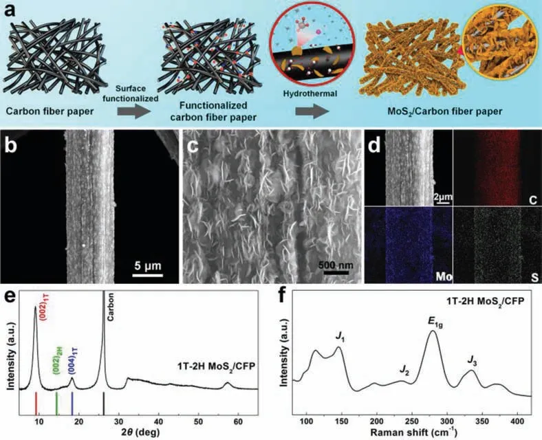
Fig.1.(a) Synthesis procedure diagram of the MoS2/CFP catalytic electrode, including surface functionalization and following hydrothermal reactions.(b, c) Low- and highmagnification SEM images of the prepared electrode.(d) EDS elemental mappings including C, Mo, and S.(e, f) XRD and Raman spectra of the prepared MoS2/CFP catalytic electrode.
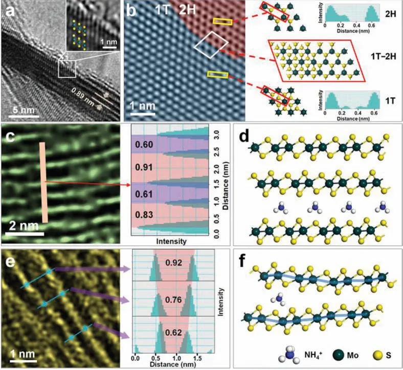
Fig.2.(a) The TEM side view of a 1T-2H MoS2 nanosheet.Insert is the magnified view from the selected area.(b) The TEM picture of the surface of the 1T-2H MoS2 nanosheet and the corresponding models and the intensity distribution of the selected region were obtained.(c) Side-view TEM image and layer spacing of a rare region of the MoS2 nanosheet in the sample.(d) Ammonia-ions intercalate the optimized structure of the models of layered MoS2.(e) Side-view TEM image and layer spacing of a particular case in a MoS2 nanosheet with a change in the adjacent layer spacing.(f) The optimized structure of the unsaturated ammonium-ions insertion model between two MoS2 layers.
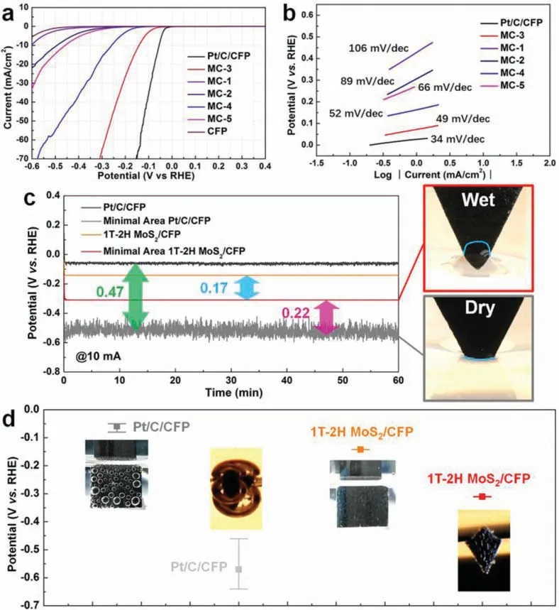
Fig.3.(a, b) The polarization curve data and the Tafel slope diagram of various catalytic electrodes.(c) A long-term stability test result of Pt/C/CFP and 1T-2H MoS2/CFP(MC-3) electrodes and their (d) error bars of the potential and potential oscillation interval, under large (1 cm2) and tiny (0.5 mm2) contact working areas.
In determining the suitability of the 1T-2H MoS2/CFP catalytic electrode in water splitting, the linear sweep voltammetry (LSV)with three-electrode configuration was used to evaluate the electrocatalytic performance of all materials in an H2SO4electrolyte solution (0.5 mol/L).The polarization curves of the prepared 1T-2H MoS2/CFP catalytic electrode compared to those of a Pt/C/CFP catalytic electrode (the preparation method is described in Supporting information) are presented in Fig.3a.The onset overpotential of the 1T-2H MoS2/CFP (MC-3) catalytic electrode isca.40 mV, which approaches the Pt/C/CFP catalytic electrode (ca.0 mV).The HER catalytic activity of CFP can be negligible in comparison to the activities of these samples.From a comparative study on the required applied overpotential to produce a current density of 10 mA/cm2, the applied overpotentials of the 1T-2H MoS2/CFP(MC-3) and Pt/C/CFP catalytic electrodes are 141 mV and 56 mV,respectively.The Tafel slope is well known to be one of the inherent parameters for evaluating the HER rate-determining steps.In Fig.3b, the Tafel slope of the 1T-2H MoS2/CFP (MC-3) electrode (49 mV/dec) is nearby that of the Pt/C/CFP electrode (34 mV/dec).According to the classic theory (Eqs.S1-S3 in Supporting information), the mechanism of Volmer-Heyrovsky is used by the 1T-2H MoS2/CFP (MC-3) catalytic electrode in HER [44,45].The long-term stability evaluation of the 1T-2H MoS2/CFP (MC-3) sample was treated under 2000 continuous cycles.Relative to those recorded previously, the obtainedI-Vcurves remained almost unchanged (Fig.S13 in Supporting information).Besides, the effects of different concentrations of raw materials (thiourea and sodium molybdate) in the precursor solution on the HER performance of the catalytic electrodes have been investigated (details in Supporting information).Although the activity of sample MC-3 is the best among the prepared 1T-2H MoS2/CFP electrodes, the activity of MC-3 is still quite away from that of noble metal Pt-based catalytic electrodes (such as Pt/C/CFP catalytic electrode).
Here, we systematically investigated the three-phase interface behavior driven by the surface properties of the HER catalytic electrode.At the same time, the stability and energy utilization efficiency differences caused by the different three-phase interface behavior between the prepared non-noble metal electrode and the noble metal catalytic electrode were analyzed.We tested the surface hydrophilicity of the catalytic electrodes in terms of water static contact angles (Fig.S14 in Supporting information).The results show that 1T-2H MoS2/CFP (MC-3) has superhydrophilic properties, while Pt/C/CFP has superhydrophobic properties.On this basis, the 1T-2H MoS2/CFP (MC-3) sample but also the Pt/C/CFP electrode was tested by the galvanostatic electrolysis at 10 mA/cm2over 60 min, to their long-term HER electrochemical stability measurement (Fig.3c).Meanwhile, Fig.3d shows the potential of various catalytic electrodes and the corresponding oscillation intervals.One interesting observation is that the 1T-2H MoS2/CFP (MC-3) catalytic electrode performed steadily (with a relatively smooth curve at a potential of 140 mV due to the rapid detachment of as-formed hydrogen bubbles before they grew too large).The large fluctuation of the Pt/C/CFP catalytic electrode indicates that the electrode surface works under unstable gas/liquid two-phase transport.The unstable mass transfer behavior can be attributed to the strong adhesion between the bubbles and the hydrophobic surface of the electrode.Despite this finding, the energy utilization efficiency of the Pt/C/CFP catalytic electrode is still superior to the 1T-2H MoS2/CFP (MC-3) catalytic electrode.
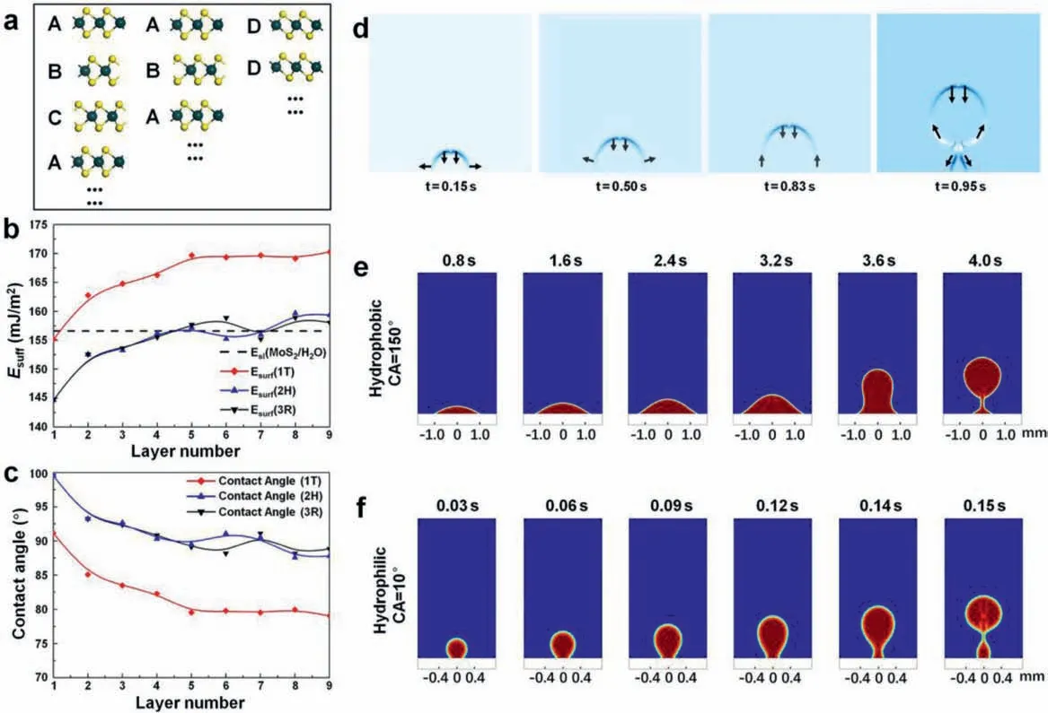
Fig.4.(a) Geometries of layered MoS2 in different phases.The ABC, AB, and DD stacking models represent the 3R, 2H, and 1T phases.Diagrams of (b) surface energy and(c) water contact angle with the number of 1T, 2H, 3R MoS2 layers.(d) Tensor distribution during the bubble generation process.The processes of bubble generation during one complete period at the (e) hydrophobic interface (contact angle of 150 degrees) and the (f) superhydrophilic interface (contact angle of 10 degrees).
In the galvanostatic test at 10 mA, we also tried to contact the electrolyte with the catalytic electrode’s tiny part (the contact area is about 0.5 mm2).The adhesion behaviors of the gas bubbles on different electrodes used for the HER were further observed.A large bubble appeared on the surface of the Pt/C/CFP catalytic electrode.The distinct difference is that the bubbles on the 1T-2H MoS2/CFP (MC-3) electrode surface separated away naturally as soon as they formed (Fig.3d and part 1 of Movie S1 in Supporting information).The 1T-2H MoS2/CFP (MC-3) catalytic electrode performed steadily with a smooth potential curve at a potential of 310 mV.In contrast, by functioning under unstable surface gas/liquid mass transport, the potential curve of the Pt/C/CFP catalytic electrode fluctuated clearly (Figs.3c and d).It is worthwhile to note that the potential of the Pt/C/CFP catalytic electrode (approximately 530 mV) is higher than the value of the 1T-2H MoS2/CFP (MC-3) catalytic electrode.It can be attributed to the attenuation of the working area caused by the inherent hydrophobicity of the Pt/C catalyst (Fig.3c).Also, hydrogen bubbles can form “gas pockets” in the pores of Pt/C/CFP, there could lead to loss of vast internal active sites, making the electrode potential had to be increased by 470 mV to maintain the working current at 10 mA.Interestingly, the 1T-2H MoS2/CFP (MC-3) catalytic electrode has a water absorption characteristic (part 2 of Movie S1).This characteristic makes the 1T-2H MoS2/CFP (MC-3) catalytic electrode work with a capillary effect during operation.This effect can be understood as a mass transfer process in which the electrolyte is flowing to the “dry area” of the catalytic electrode.The unique three-phase behavior not only enlarges the real work area of the catalytic electrode but also gives an extensive “wet area” that could even participate in the test (Fig.3c and part 3 of Movie S1).Therefore, the electric potential of the 1T-2H MoS2/CFP(MC-3) catalytic electrode went up by only 170 mV.These results further confirm that the three-phase interface behavior dominated by the hydrophilic surface of the catalytic electrode can improve the energy utilization efficiency and stability of the hydrogen evolution.
The hydrophilicity of MoS2nanosheets is studied in detail to determining the reasons for the formation of excellent hydrophilicity on the 1T-2H MoS2/CFP catalytic electrode surface.Studies on the 2H, 1T, and 3R polymorphs of low-dimensional materials have been increasing [46].Our work presents the calculation data of all three MoS2phases.Different phases of MoS2have different spatial structures.Fig.4a shows the polymorphs of MoS2.The stacking order of the 3R phase and the 2H phase MoS2layer array is ABC and AB, respectively, while in 1T-MoS2, each layer is the same.In the ABC stacking sequence, the arrangement repeats every three layers with a slight stagger of the neighboring layers in the a-axis direction of the lattice.Similar characteristics were observed in the AB stacking, but the structure repeats every two layers.Herein, we constructed models of layered MoS2of the three phases from a monolayer to nine layers (all shown in Fig.S15 in Supporting information).Afterward, the geometries of all of the layered MoS2models were optimized [47], and the total optimized energies were determined.The surface energy of the MoS2with layer number ofn(Esur(n)) can calculate by using the following expression (Eq.1):

wherenrepresents the number of MoS2layers,Enis the overall energy of the optimized layered MoS2model (exact values are shown in Table S2 in Supporting information).Ebis the gross energy of the bulk MoS2,which has no vacuum layer and represents situations with no surface, which is essential for the accuracy of theEsurresults (Table S3 in Supporting information presents the detailedEbresults).Nis the specific value of the number of atoms in the layered MoS2model to that in the corresponding bulk MoS2model.S is the surface cell area [48].
As the function of layer number, the surface energy is presented in Fig.4b (exact values see Table S4 in Supporting information).For all polymorphs of MoS2, the surface energy increases withnwhennis smaller than 5.However, oncenis greater than 5, the surface energy begins to converge, with only slight increases or decreases in the energy asncontinues to increase.It indicates that the surface characteristics of layered MoS2with more than 5 layers are similar.Besides, the surface energy of MoS2with 1T phase is usually higher than that of the other two phases, which is caused by the different coordination geometries in 1T-MoS2.In the 1T phase,one Mo center is octahedrally coordinated by six S atoms and prismatically coordinated in the 2H and 3R phases (Fig.S1 in Supporting information).This distinct structure enables the surface of 1TMoS2more active for covalent functionalization than the 2H and 3R counterparts.It further leads to higher surface energy in the 1T phase.In addition, the water contact angle is measured to evaluate the hydrophilicity and is calculated by the following expression(Eq.2) [49]:
whereEsandElare the solid and the liquid surface energy, respectively.Eslis the solid-liquid interface energy.To calculate the water contact angleθ, the values ofEl,EsandEslmust be ascertained.Elis the surface energy of water with a chosen value of 72 mJ/m2[50].Esis the surface energy of the layered MoS2.We considerEslto be a constant (156.589 mJ/m2) since the type of solid and liquid are fixed (particulars of selecting the relevant final value are in the Supporting Information section).In Fig.4b, the line of dashes represents the value ofEsl; whenEsis above this line, the contact angle is an acute angle, which indicates relatively good hydrophilicity.Fig.4c presents the theoretical values of the water contact angle when calculated according to Eq.2, and the exact values are presented in Table S5 (Supporting information).Much like the surface energy sequels, the contact angle changes only slightly under the condition that the layer number is larger than 5, which implies that an additional layer for MoS2materials contributes little to the hydrophilicity after the number of layers exceeds 5.The results show that 1T-MoS2has a smaller water contact angle than 2H and 3R MoS2, which indicates that 1T-MoS2has better hydrophilicity.On the other hand, the hydrophilicity of the material itself can be greatly increased by the formation of rough nanostructured interfaces [51,52].Therefore, in the prepared 1T-2H MoS2/CFP catalytic electrode, the 1T phase MoS2is dominant with a porous structure and rough interfaces, which explains the excellent hydrophilicity.
Further, studying the fluid tensor distribution similar to the HER environment is used to analyze the influence of the three-phase interface behavior on the prepared electrode surface, reaction stability, and energy utilization efficiency.As shown in Fig.4d, the arrows describe the direction of the tensor, and the color represents the magnitude of the tensor.At the beginning of the bubble generation, a small amount of hydrogen gathers and adheres to the surface of the catalytic electrodes due to the surface adsorption force.The bubble spreads rapidly along the radial direction but slowly in the vertical direction; thus, the bubble sticks on the catalytic electrode surface in a flat form.It is the so-called budding stage.As the bubbles grow, the direction of the bubble top tensor remains downward due to hydraulic pressure.Still, the direction of the bubble bottom tensor varies from lateral to upward due to the joint effect of the interfacial absorption force and the floating force.This arrangement is the spreading stage.As hydrogen is produced continuously and the bubble volume increases, the interfacial adsorption force effect decreases relative to the buoyancy.Growth in the radial direction slows, and vertical growth begins accelerating.The bubble is gradually drawn out.This arrangement is the stretching stage.As the bubble length increases to a particular value, the middle of the bubble starts shrinking since the uplift force at the top and the adsorption force at the catalytic electrode surface act in opposite directions.This arrangement is the shrinking stage.As a result, the shrinking tensor accelerates the flotation of the bubble toward the air region.In contrast, the adsorption force accelerates hydrogen gathering at and detaches from the catalytic electrode surface.The remaining hydrogen will reattach to the catalytic electrode surface, forming the next bubble.Thus, the influence of the surface adsorption force throughout the whole process of hydrogen bubble formation can be seen.The bubble morphology formed at the hydrophilic and hydrophobic surfaces was further studied through the time-dependent nephogram of the fluid distribution, which matches the corresponding surfaces of the 1T-2H MoS2/CFP (MC-3) and Pt/C/CFP catalytic electrodes (Figs.4e and f).The radial-spreading stage lasts longer on the hydrophobic surface, and more hydrogen concentrates on the surface before fully forming a bubble.In sharp contrast, the bubble radius on the superhydrophilic surface is much smaller, while the bubble generation rate is higher than that on the hydrophobic interface (Movie S2 in Supporting information).The results of fluid dynamics simulations indicate that compared with the hydrophobic surface, the hydrophilic surface has a weak adsorption capacity on the bubble surface, which is beneficial to the release of hydrogen and the reduction of the contact area between the gas and the catalytic electrode surface.In other words, as a benefit from the hydrophilic characteristic, the surface of the 1T-2H MoS2/CFP catalytic electrode in HER will exhibit a rapid gas-liquid mass transfer behavior.This three-phase interfacial mass transfer behavior is beneficial for the electrode to maintain a stable working area and increase the generation rate of the hydrogen bubbles [53].Besides, a simple model (Fig.S16 in Supporting information) was proposed to illustrate the synergistic effect of the prepared sample (MC-3) during the HER process.
In summary, a case study of the 1T-2H MoS2/CFP catalytic electrode was conducted.The results show that the catalytic electrode has good hydrophilicity, which can accelerate the gas-liquid mass transfer efficiency between the solid-liquid-gas three-phase interface in the hydrogen evolution process at the micro-scale, thus providing a stable working area.In a very small area contact of electrode and electrolyte during the HER, the 1T-2H MoS2/CFP catalytic electrode is accompanied by capillary behavior, which promotes the energy utilization efficiency of the prepared electrode to be superior to that of the Pt/C/CFP catalytic electrode.The MoS2-based electrode promises to replace the Pt-based catalytic electrode in specific cases.Non-uniform NH4+ion intercalation could be the main factor that leads to the coexistence of the 1T and 2H phases in the MoS2.The wettability evaluation indicates that the excellent hydrophilicity of the 1T-2H MoS2/CFP catalytic electrode is mainly due to the leading role of 1T MoS2and the existence of more than 5 layers of MoS2nanosheets.The fluid dynamics simulation results show that the superhydrophilic electrode surface can boost the frequency of hydrogen production and minimize bubbles duration time.The three-phase interfacial mass transfer behavior is a non-negligible factor in the HER, which affects both the stability of the hydrogen bubble formation and energy utilization efficiency.
Declaration of competing interest
The authors declare that they have no known competing financial interests or personal relationships that could have appeared to influence the work reported in this paper.
Acknowledgments
This work was supported by the National Natural Science Foundation of China (No.62004051), the Natural Science Foundation of Heilongjiang province (No.LH2020F013), the China Postdoctoral Science Fund (No.2020M670909), and the Heilongjiang Postdoctoral Science Fund (No.LBH-Z19017).
Supplementary materials
Supplementary material associated with this article can be found, in the online version, at doi:10.1016/j.cclet.2021.11.007.
 Chinese Chemical Letters2022年8期
- Chinese Chemical Letters的其它文章
- Adsorptive removal of PPCPs from aqueous solution using carbon-based composites: A review
- A review on hollow fiber membrane module towards high separation efficiency: Process modeling in fouling perspective
- Recent advances in DNA glycosylase assays
- Chiral pillar[n]arenes: Conformation inversion, material preparation and applications
- Recent progress in carbon-based materials boosting electrochemical water splitting
- Working principle and application of photocatalytic optical fibers for the degradation and conversion of gaseous pollutants