Dry passivation of austenitic SUS 301L stainless steel against pitting corrosion in marine atmospheric environment*
Yonghong LU , Xiao LIU , Lisha WANG , Jinghong YANG ,**, Haibo XU ,**
1 Key Laboratory of Marine Chemistry Theory and Technology, Ministry of Education; College of Chemistry and Chemical Engineering, Ocean University of China, Qingdao 266100, China
2 CRRC Changchun Railway Vehicles Co., Ltd., Changchun 130062, China
Abstract Being an exclusive construction material for lightweight rail vehicles, protection from pitting corrosion in harsh marine atmospheric environment in high humidity and Cl - ion concentration is critical for austenitic SUS 301L stainless steel (SS), especially when it inevitably suff ers from mechanical damages during post disposals. Herein, an innovative dry passivation method for austenitic SUS 301L SS was established in a closed air atmosphere at low temperature and constant pressure. The process parameters were optimized, and the passivation mechanism was explained using polarization curve, electrochemical impedance spectroscopy (EIS), X-ray photoelectron spectroscopy (XPS), and contact angle measurement.The pitting corrosion susceptibility of the passive film prepared in a closed air chamber under 1.0×10 5 Pa at 80 °C for 80 min was evaluated in 3.5% NaCl solution and exhibited higher pitting potential and corrosion resistance, lower passivity-maintaining current density, and wettability when compared with conventional nitric acid treatment. Besides, dry passivation facilitated the repairing of the surface structural defect itself and the post-processing damage, similar to the accelerated aging of film. The decrease in oxygen concentration and convection-diff usion strengthened the preferential chromium oxidation to form a compact chromium-rich passive film to resist the aggression of Cl - ion.
Keyword: austenitic stainless steel; passive film; dry passivation; pitting corrosion; chloride ion
1 INTRODUCTION
Stainless steel (SS) is regarded as one of the most technologically important alloys in the industrial sector because ofits high toughness, easy-processing ability, aesthetic function, and most valuably, selfprotection against corrosion (Loto, 2015). In the air, a few nanometers thick oxide film is naturally formed on SS substrate, which is called natural or native passive film (NPF) (Gardin et al., 2018; Rahimi et al.,2019; Långberg et al., 2020). However, the NPF has defects that easily suff er from localized corrosion in the aggressive medium in the presence of chlorides(Ibrahim et al., 2009; Loto, 2013). Ma et al. (2020)investigated the surface structure and initial oxidation mechanism of Fe-18Cr-13Ni SS at nanometric and atomic scales, revealing the impact of chromium-rich oxide nuclei and locally chromium-depleted terraces on subsequent surface corrosion. Therefore, following the production of the SS sheet, acid-based chemical passivation treatments are often applied to remove the surface contaminants and acquire the compact oxide film vividly called factory-produced passive film(FPF) via a tedious procedure of pickling, oxidation,neutralization, rinsing, and even long-time aging.Noh et al. (2000) and Salvago et al. (1994) confirmed that the chemical passivation or pickling treatment could largely improve the pitting resistance of SS.
With a low carbon and nitrogen content, austenitic SUS 301L SS is the exclusive construction material for lightweight rail vehicles due to its great ductility,strong strength, and good welding performance, for example meeting high requirements for uniformity and flatness of outer panel as well as strength and rigidity of framework. However, in real applications,the FPF present on the surface inevitably suff ers from mechanical damages during manufacturing,assembling, or welding disposals, thereby making it susceptible to pitting corrosion in the subsequent process of storage and transportation in the marine atmosphere with high humidity and Cl-ion concentration (Loto, 2013; Liu et al., 2018). Loto(2015) reviewed that the damage caused by scratches to the protective film results in an anodic reaction on the metal surface; hence, the protective surrounding acts as the cathode. Consequently, it accelerates the pitting corrosion due to large cathodic area and small anodic area.
Considering the passivation method, the chemical or electrochemical treatments relevant to the liquid environment are called wet passivation or wet oxidation methods, and the resulted oxide layer is called wet-method passive film (WPF) (Sun et al.,2019). After nearly 100 years of development,industrial passivation is still dominated by nitric acidbased chemical processes along with the practice ofimpregnating, spraying, or paste coating. This unavoidably leads to a huge amount of acid-containing wastewater during the pickling and rinsing procedure(Liu et al., 2018; Sun et al., 2019). Moreover, Cho et al. (2000) observed that wet processing is not suitable for fabricating chromium oxide film needed in some applications due to high water retention in the film. In addition, the long-term stability of the passive film via the wet method was uncertain, and its self-repair ability was regarded as to be temporary (Carroll and Howley, 1990; Crolet, 1997). Nowadays, with the increasing demand for environmental protection and anticorrosive endurance in the marine atmosphere,there is an urgent need to develop green and effi cient SUS 301L SS passivation technology to replace the wet oxidation method.
It is well known that SS alloys can be oxidized in the air or mixed gas atmosphere (Allen et al., 1988;Ohmi et al., 1993; Gui et al., 2017) or under high vacuum (Greyling and Roux, 1984; Langevoort et al.,1987; Cho et al., 2001), and the process is called dry passivation, thermal passivation or dry oxidation, and the oxide layer formed is called dry-method passive film (DPF). However, some DPFs exhibit weak or ordinary self-protection ability, such as NPF, while others frequently involve complicated controls for temperature, pressure, or atmosphere. For example, a complete chromium oxide passivation technology was developed in a mixture of 10% hydrogen, (1-10)×10-6oxygen, and argon balance gas at 500 °C for 1 h (Ohmi et al., 1993). Cho et al. (2000) prepared a smooth Cr2O3oxide film at 450 °C with oxygen pressure lower than 1.33×10⁻⁶Pa. These disadvantages largely limit the use of dry passivation. Alternatively,we resort to a simple control method to prepare the DPF in an enclosed air atmosphere under 1.0×10⁵Pa and at a temperature below 150 °C, which exhibited marvelous corrosion resistance. Considering its apparent merits oflow requirements for temperature,pressure, and atmosphere, low cost, and ecofriendliness, the dry passivation method is especially suitable for the treatment oflarge SS parts such as vehicle body which are always restricted by the volume of passivation tank, film homogeneity, and severe environmental pollution, and is worthy of meticulous investigation.
This work aimed to determine suitable operating conditions for dry passivation of austenitic SUS 301L SS in detail by systematically evaluating the pitting corrosion susceptibility in 3.5% NaCl, simulating the influence of Cl-ion in the marine atmosphere compared with wet passivation, and discussing the preliminary passivation mechanism. The results reported here are expected to provide new insight into the viable industrial route for the formation of the anticorrosive passive film, which has been restricted by conventional wet methods for a long time.
2 MATERIAL AND METHOD
2.1 Material and sample preparation
The commercial SUS 301L sheet with a thickness of 1 mm was procured from Shanghai Baogang Stainless Steel Co., Ltd. The chemical composition(wt.%) of the sample was a follows: Cr 16.00-18.00,Ni 6.00-8.00, Mn<2.00, Si<1.00, N<0.20, P<0.045,S<0.030, C<0.030, and the balanced Fe. The sheet was cut into 20 mm×20 mm specimen and marked as the FPF sample. Several FPF specimens were polished with 300-grit waterproof abrasive paper to regain the fresh surface and rinsed with distilled water, followed by drying with filter paper. Later they were treated separately and named accordingly as follows: NPF was the sample naturally exposed to laboratory air for up to 24 h. WPF was the one immersed in 25% nitric acid passivation solution at room temperature (RT,25 °C) for 30 min and then rinsed repeatedly with distilled water till to neutralization. DPF samples were obtained by keeping the fresh samples into a preheated tube furnace (80 °C and 140±1 °C) with air vent open, followed by heating for 20-120 min with air vent open or closed, and finally cooled down to RT. These samples were marked as DPF-T-t-ON or DPF-T-t-OFF-Pi, whereTandtstand for the heating temperature (°C) and time (min), ON or OFF represents air ventilating state, i.e., the inlet/outlet valves of tube furnace were open or closed to permit or stop the natural convection of cold/hot air, andPirepresents an absolute pressureP0(1.0×10⁵Pa),P1(0.6×10⁵Pa), andP2(0.2×10⁵Pa) by pumping air out,orP3(~1.3×10⁵Pa) by introducing 0.4-L pure oxygen.
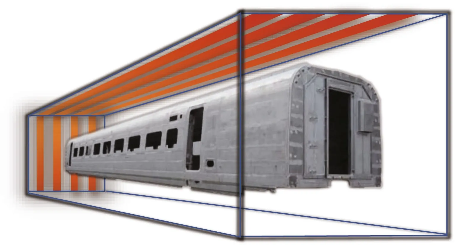
Fig.1 Scheme of dry passivation of the stainless steel vehicle body in closed industrial air chamber under 1.0×10 5 Pa at 80 °C for 80 min
To compare the repassivation eff ect, the FPF samples subjected to wet or dry disposal were marked as FPF-WPF and FPF-DPF. Additionally, before repassivation, the FPF surface was manually scratched using a nail along the two diagonal lines to form a cross with a width of ~ 0.5 mm and marked as FPF-X samples and then passivized by wet or dry disposal to obtain the FPF-X-WPF and FPF-X-DPF samples.The wet repassivation procedure via nitric acid was the same as the above, and the dry repassivation was carried out at 80 °C in a closed air chamber under 1.0×10⁵Pa for 80 min.
To simulate the dry passivation of the whole vehicle body in the industrial air chamber as shown in Fig.1, three large pieces of SUS 301L SS sheets of 450 mm×300 mm, representative of a typical 3D location of the vehicle body panel, were put obliquely(A sheet), vertically (B sheet), and horizontally(C sheet), respectively, inside an ordinary constant temperature drying oven (FXB101-1, Shanghai Shuli Instrument Co., Ltd., China) instead of the tube furnace with the better sealing condition. The air vent at the top of the oven was plugged with asbestos cloth,and the three FPF samples were heated at 80±1 °C for 80 min. After that, a total of six pieces of 20 mm×20 mm FPF-DPF specimens were cut off from the three sheets for corrosion evaluation, i.e., A1and A2from A sheet, B1and B2from B sheet, and C1and C2from C sheet.
2.2 Electrochemical measurement
SS sample was assembled as the working electrode(1-cm2surface area) in the Flat Cell K0235 threeelectrode cell (AMETEK Princeton Applied Research,USA), a platinum electrode as the counter electrode,and a saturated calomel electrode (SCE) as the reference electrode. All potentials were relative to SCE. 3.5% NaCl was used for the accelerated test of pitting corrosion due to the high susceptibility of SS to Cl-ion, as reported in the literature (Ibrahim et al.,2009; Loto, 2015). Polarization curve measurements were carried out at 1-mV/s scan rate using an EG&G PAR Model 273A Potentiostat/Galvanostat, from the open circuit potential (OCP) to the potential corresponding to a current density of not more than 100 μA/cm2. The electrochemical impedance spectroscopy (EIS) was carried out at 0.0 V, a typical passivation region, with ±10 mV potential amplitude and a frequency range of 0.01-100 kHz, using an EG&G PAR Model 2263 Potentiostat/Galvanostat.
2.3 Surface characterization
The surface of a few samples was examined using argon ion sputtering and X-ray photoelectron spectroscopy (XPS) to obtain compositional depth profiles of the passive film. XPS was carried out using ESCALAB250 energy spectrometer (Thermo VG,UK), Al Kα as the excitation source (l5 kV, 10 mA)under the cavity pressure of 5.5×10⁻⁶Pa. The thickness of the passive layer was determined using a raster 2 000-eV argon ion beam for a sputtering time of 0-105 s. The etching speed estimated via etching of Ta2O5samples was 7 nm/min. The contact angle was measured by DSA-100 optical contact angle measuring instrument (KRüSS, Germany). Briefly, a drop of 3-μL deionized water from a microsyringe was dropped on the SS surface and the camera system was controlled to capture the image of the droplet attached to the surface film. After determining the baseline, the software automatically calculated the contact angle of the SS surface by taking 10 readings to obtain the average value.
3 RESULT AND DISCUSSION
3.1 Dry passivation
The oxide film formed on the SS surface usually consists of diff erent iron and chromium oxides depending on the alloy composition and oxidizing conditions (such as oxidizing atmosphere, time, and temperature). The SS samples were kept in a tube furnace already heated to a preset temperature with the air vent open. The air vent of the furnace was sealed after putting the sample. The change in air content could be obtained from Eq.1:

wherenis the molar number of air,Vis the volume of furnace cavity (~2 L),Pis the air pressure,Ris the constant equal to 8.314, andTis the heating temperature. According to Eq.1, the air content is inversely proportional to the temperature. Before or after sealing the air vent, the pressure inside the furnace was a normal pressure of 1.0×10⁵Pa. With the rise in heating temperature, the air and oxygen content inside the furnace was decreased by 22.7%(80 °C) and 33.9% (140 °C), respectively, from the normal temperature (0 °C), which constituted a basic environmental condition for dry passivation.
According to the transfer rate and oxygen concentrationCO2, we devised several gas conditions in the heating furnace. The inlet/outlet valve of the tube furnace was opened or closed after preheating the furnace to 140 °C and keeping the temperature constant for 30 min (P0=1.0×10⁵Pa,CO2=12.4 mmol/L). In the case of a sealed furnace, a part of air was pumped out (P1=0.6×10⁵Pa,CO2=7.4 mmol/L andP2=0.2×10⁵Pa,CO2=2.5 mmol/L), or 0.4-L pure oxygen was introduced (P3=~1.3×10⁵Pa,CO2=21.3 mmol/L)followed by drying for 80 min to obtain DPF-140-80-ON, DPF-140-80-OFF-P0, DPF-140-80-OFF-P1,DPF-140-80-OFF-P2, and DPF-140-80-OFF-P3,respectively. The oxygen convective transfer rate was ranked from high to low as DPF-140-80-ON > DPF-140-80-OFF-P0, and the oxygen concentration was in the following order: DPF-140-80-OFF-P3> DPF-140-80-OFF-P0> DPF-140-80-OFF-P1> DPF-140-80-OFF-P2.
The pitting corrosion susceptibility of the passive film depends on the two parameters of the polarization curve: the breakdown potentialEb, also known as pitting potential, which corresponds to the turning point of the potential from passivation to activation and is defined as the potential at which the current density monotonically increases to ca. 10 μA/cm2(Li et al., 2019) and the another is the passivitymaintaining current densityip, necessary to maintain the stability of the passive film and a reflection ofits self-recovery ability (Okamoto, 1973). In general,both highEband lowipare required for a better passivation eff ect.
The potentiodynamic polarization curves of the five samples prepared at 140 °C for 80 min revealing the influences of oxygen concentration and transfer rate on the passivation eff ect, are shown in Fig.2a.EachE~islope on the curves coincided while moving towardEb, indicating that alliphad the same increasing tendency, and the passive films had a similar selfrepairing ability. However, theirEbvalues were diff erent. On comparing DPF-140-80-OFF-P0with DPF-140-80-ON, it was observed that under diff erent air ventilating states, the former had a much higherEb(about 150 mV more), indicative of a favorable eff ect of the enclosed chamber from weakened air convection-diff usion.
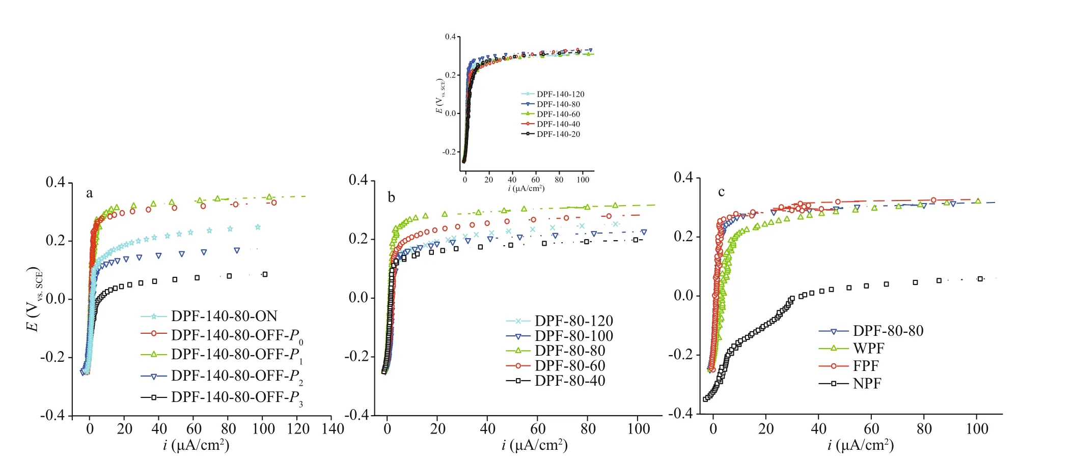
Fig.2 Polarization curves of SUS 301L SS in 3.5% NaCl
Once 40% air was pumped out of the closed furnace, DPF-140-80-OFF-P1(P1=0.6×10⁵Pa,CO2=7.4 mmol/L) hadEbequal to 280 mV, similar to that of DPF-140-80-OFF-P0(P0=1.0×10⁵Pa,CO2=12.4 mmol/L); however, after a reduction of 80%air, theEbof DPF-140-80-OFF-P2(P2=0.2×10⁵Pa,CO2=2.5 mmol/L) was greatly decreased by ca.170 mV, even lower than that of DPF-140-80-ON.Conversely, when the oxygen concentration was raised from 12.4 mmol/L to 21.3 mmol/L, the DPF-140-80-OFF-P3(P3=~1.3×10⁵Pa,CO2=21.3 mmol/L)a. dry passivation at 140 °C for 80 min in open chamber in the case of DPF-140-80-ON (P0=1.0×10⁵Pa,CO2=12.4 mmol/L) or closed chamber for DPF-140-80-OFF-P0(P0=1.0×10⁵Pa,CO2=12.4 mmol/L), DPF-140-80-OFF-P1(P1=0.6×10⁵Pa,CO2=7.4 mmol/L), DPF-140-80-OFF-P2(P2=0.2×10⁵Pa,CO2=2.5 mmol/L), and DPF-140-80-OFF-P3(P3=~1.3×10⁵Pa,CO2=21.3 mmol/L); b. dry passivation at 80 °C (inset at 140 °C) with diff erent heating times;c. DPF-80-80 (dry-method passive film generated in the closed chamber at 80 °C for 80 min), WPF (wet-method passive film by 25% nitric acid disposal),FPF (factory-produced passive film), and NPF (native passive film).had a huge drop inEb, more than 270 mV as expected.Hence, it could be inferred that both slow oxygen transfer rate and an appropriate oxygen deficiency were beneficial to the dry passivation. In addition, a closed air chamber and suitable oxygen concentration depending on the heating temperature were highly necessary and eff ective to control the passivation.
Considering the heating temperature, passivation at a high temperature not only consumes a lot of power but causes diffi culty in equipment cost and operation control; meanwhile, it is always restricted by the temperature tolerance limit of auxiliary nonmetallic parts including plastic, rubber, or composite material. Therefore, a lower temperature of 80 °C and a practical heating time of 20-120 min was tested. It is worth mentioning that a closed air chamber under a pressure of 1.0×10⁵Pa was also highly beneficial.
Polarization curves of DPF generated at 80 °C with diff erent heating times are shown in Fig.2b. Nearly the same changes inipand large diff erences inEbvalues were observed. TheEbof DPF-80-80 reached a maximum of 0.25 V, whereas that of DPF-80-60,DPF-80-100, and DPF-80-120 were equal to 0.20 V,0.15 V, and 0.15 V, respectively, indicating an unfavorable eff ect oflonger heating time. At 140 °C(inset of Fig.2b), the DPF-140-20 also showed a higher value ofip, and the diff erence betweenEbvalues of DPF-140-20 and DPF-140-120 was less than 30 mV. Additionally, theEbvalue of DPF-140-80 was close to that of DPF-80-80, and they both had low values ofipnot more than 5 μA/cm2. This suggested that a passive film was quickly formed within 20 min,and it exhibited the best anti-corrosion ability for longer exposure of up to 80 min. Since a compact passive film with a constantly lowipvalue could be easily formed at lower temperatures, and considering the above results, a low heating temperature of 80 °C was preferred. Moreover, based on these comparisons,a heating time of 80 min was preferred.
Subsequently, the polarization curves of diff erent SS passive films, including NPF, FPF, and WPF formed by nitric acid treatment and DPF-80-80 (in a closed tube furnace at 80 °C for 80 min) were compared in Fig.2c. The NPF displayed the lowestEband rapidly increasedip, which was an indication of the worst anti-corrosion property as expected. DPF-80-80 hadEb(0.25 V) andip(less than 5 μA/cm2)values similar to FPF; thus, confirming an excellent pitting corrosion protection by dry passivation, even comparable to FPF with long-time aging. The aging after passivation was found to largely increase the pitting corrosion resistance (Wallinder et al., 1998).Whereas the WPF exhibited an increasing value ofipup to >10 μA/cm2and anEbof ca. 0.20 V, better than NPF but inferior to DPF and FPF.
3.2 Dry repassivation
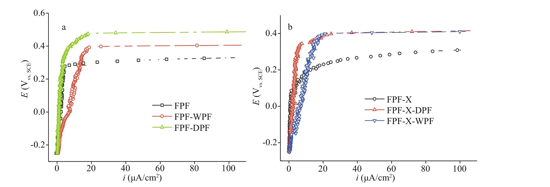
Fig.3 Polarization curves of FPF, FPF-DPF (dry repassivation in a closed chamber at 80 °C for 80 min on FPF), and FPFWPF (a) and FPF-X (scratched FPF), FPF-X-DPF, and FPF-X-WPF in 3.5% NaCl (b)
SS repassivation is the important surface treatment to repair the passive film. The polarization curves of the FPF passive films after undergoing dry repassivation in a closed tube furnace at 80 °C for 80 min (FPF-DPF) and nitric acid repassivation FPFWPF are shown and compared with the original FPF in Fig.3a. FPF-DPF showed a low increasing rate ofipand a much higherEb(about 150 mV higher) in comparison to FPF. However, theipof FPF-WPF kept on rising rapidly and the passive film eventually broke down at 0.40 V. These results confirmed an excellent pitting corrosion protection of FPF-DPF by dry repassivation and might be regarded as accelerated aging for FPF, which in turn resulted in an improved film quality by reducing the weak points and increasing the film compactness (Wallinder et al.,1998; Wang et al., 2019). However, a rapid increase inipby wet processing was ascribed to the preferential iron dissolution in acidic media, which did not only lead to a significant chromium enrichment in the oxide layer but also deteriorated the film compactness(Gardin et al., 2018).
Furthermore, deep scratches were made artificially on FPF (FPF-X) to simulate the damages resulted from post-processing, followed by dry and nitric acid repassivation. The polarization curves of FPF-X,FPF-X-DPF, and FPF-X-WPF are compared in Fig.3b. In the case of the severely damaged FPF-X,both dry and wet methods could greatly increase theEbby more than 150 mV. However, rapidly increasedipin FPF-X-WPF indicated an inferior repairing eff ect in comparison to dry repassivation due to worse film compactness. Additionally, compared with FPF, theEbvalue of FPF-X-DPF was increased by about 80 mV, while that of FPF-DPF by 150 mV, hence manifesting the importance of film compactness.
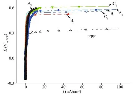
Fig.4 Polarization curves of FPF and FPF-DPF (A 1, A 2, B 1,B 2, C 1, and C 2) prepared in an ordinary drying oven in 3.5% NaCl
To verify the feasibility and operational flexibility of the industrial process and the homogeneity of passive film for large SS parts, the polarization curves of six FPF-DPF samples, which were cut from large samples placed in a sealed ordinary drying oven and treated at 80 °C for 80 min were compared with FPF and are shown in Fig.4. Six samples maintained identically smallipand highEbvalues in the range of 0.50-0.57 V, consistent with the eff ect of dry repassivation in a tube furnace as shown in Fig.3a.The results revealed that an ordinary heating condition could conveniently replace the well-sealed tube furnace to obtain good reproducing results as long as the uniformity of air convection and temperature in the closed chamber is guaranteed. Meanwhile, it is worth noting that there is no restriction on the dimensions of steel elements protected in accordance with the developed methodology as long as what dimension of heating chamber can be provided. Thus,an enlarged heating chamber could be easily constructed for bulky components to acquire the uniform protection eff ect as illustrated in Fig.1,convincingly manifesting a promising prospect for the industrial application.
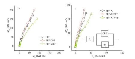
Fig.5 Nyquist impedance spectra of FPF, FPF-DPF, and FPF-WPF (a), FPF-X, FPF-X-DPF, and FPF-X-WPF at 0.0 V (vs.SCE) (b)
Additionally, the Nyquist impedance curves of FPF, FPF-DPF, FPF-WPF, and the scratched FPF-X,FPF-X-DPF, and FPF-X-WPF were evaluated by EIS as shown in Fig.5a-b. The equivalent circuit shown in the inset of Fig.5b was used for the quantitative evaluation of the spectra, resulting in a good fitting as listed in Table 1, whereRsrepresents solution resistance, and CPE is a constant phase element. The admittanceYand impedanceZwere expressed as Eqs.2 & 3:
Y=Ym(jω)n, (2)
Z=(1/Ym)(jω)-n, (3)whereYmis the magnitude of CPE,ωis the angular frequency, andnis the exponential term relating to the roughness of the electrode surface. Whenn=1,CPE is equivalent to the capacitance.
Polarization resistanceRpstrongly depends on the corrosion resistance of the passive film in the environment. Regardless of the scratches, the impedances of FPF-DPF and FPF-X-DPF were the highest, whereas those of FPF-WPF and FPF-X-WPF were the lowest, even lower than FPF, as per the results ofipin Fig.3. In the equivalent circuit, CPE was utilized instead of a capacitance because the measured capacitance is often not ideal; hence the fitting results are mentioned in terms of bothYmandn(Lu et al., 2010). The capacitive response of samples could indicate how the thickness of the passive film changes during the treatments (Wallinder et al., 1998).Besides, after dry repassivation,Rpincreased, whileYmdecreased, and higher resistance probably indicated a thicker or more compact film. Moreover, after nitric acid repassivation, the value ofndeviated more from the ideal capacitance ofn=1, indicating a deterioration in the film compactness.
In summary, dry passivation generated DPF on the fresh surface of SS, whose anticorrosive ability was comparable to FPF. Moreover, dry repassivation carried out on FPF (i.e., FPF-DPF) increased the filmcompactness or thickness as well as the repair of damages, similar to an accelerated aging process. The prepared passive films had high resistance and breakdown potential, and low passivity-maintaining current density, superior to those obtained by the conventional wet method.
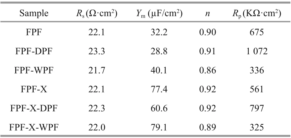
Table 1 Impedance fitting parameters of FPF, FPF-DPF,FPF-WPF, FPF-X, FPF-X-DPF, and FPF-X-WPF
3.3 Discussion on the mechanism
The growth rate of the thickness of the oxide film depends on the inward oxygen diff usion or outward metal migration, and the dissolution and formation of the film maintain a delicate balance to keep a steady passivation state. The surface element compositions of FPF, FPF-DPF, and FPF-WFP were examined by XPS in combination with the argon-ion etching, and the elemental percentage curves of chromium, iron,and nickel as a function of sputtering time are shown in Fig.6. However, the elements present in trace amounts were omitted. The three samples showed a similar trend of a decrease in chromium and an increase in iron content and a constant nickel content from film surface to the metal substrate. This confirmed the typical passivation characteristic of chromium enrichment in the surface oxide and agreed with the results of Olefjord and Wegrelius (1990),who observed a very low nickel content in the film.

Fig.6 Surface element compositions of FPF (a), FPF-DPF (b), and FPF-WPF (c) analyzed by XPS
At the surface, a higher chromium level in FPFWPF (52 at.%) than FPF and FPF-DPF (40 at.%) was observed, and it became constant after 15 s, whereas the chromium level of FPF and FPF-DPF was constant after 45 s. The film thickness was reduced by about 7 nm in an etching time of 60 s, and therefore the approximate film thickness was estimated (Ohmi et al., 1993). An etching time of 45 s for FPF and FPFDPF resulted in a thickness of no less than 5 nm. FPFDPF showed no apparent thickness increment than FPF, alternatively indicating the formation of a compact passive film due to the compatibility between FPF and DPF.
Dry passivation carried out in the air under 1.0×10⁵Pa at 80 °C showed a weak oxidation power.Therefore, the mechanism for chromium oxide enrichment in the passive film could be explained thermodynamically. At such a low temperature, the diff usion rates of chromium and iron not only in the bulk alloy but also in the natural oxide layer were found to be too slow, so that they could be ignored(Cho et al., 2001). Thus, the oxidation rate depends on oxygen concentration and its diff usion for the formation of the passive film. Chromium (III) oxide has the highest negative free energy of formation in all likely oxidation products (Samsonov, 1982). Thus,it is understandable that the iron oxidation is inhibited and the preferential chromium oxidation can be realized by controlling the appropriate atmospheric condition of oxygen.
Besides, with the increase in heating time, the majority of chromium is oxidized at the surface, and the iron takes the place of chromium to occupy the dominant oxidation position resulting in the deterioration of corrosion resistance of the passive film. With the development of complete chromium oxide (Cr2O3) passivation technology, the researchers observed that the 1-h treatment gave the thickest chromium oxide passive film, but the treatment for 1 h >t>2 h increased the amount ofiron oxide on the surface (Ohmi et al., 1993).
However, an etching for 15 s resulted in a thickness of not more than 2 nm in the case of FPF-WFP, which was even thinner than FPF. According to the study reported in the literature (Noh et al., 2000), the simultaneous dissolution ofiron/iron oxides in acid solution and enrichment of chromium/chromium oxide on the surface inevitably led to the reconstruction of the passive film on FPF. A large amount of chromium on FPF-WPF surface guarantees the highEb. However, as a side eff ect, the acid corrosion attenuates the thickness and compactness of the original FPF, and a thinner and porous passive film is fragile in harsh Cl-ion solution which is probably the reason of highipand low resistance. It has been asserted that the positive eff ect of nitric acid treatment was only temporary, and it might prevent early failures, but did not change the long-term stability(Carroll and Howley, 1990; Crolet, 1997).Furthermore, Cho et al. (2000) stated that the water might remain inside the film and perhaps could be a possible hazard of pitting corrosion in the wet method.Whereas in the case of FPF-DPF, dry repassivation impossibly dissolves the metal and surface composition, and film thickness is seldom changed,thereby indicating the formation of a compact passive film and a beneficial eff ect of a possible repair to structural defects.

Fig.7 Surface contact angle of FPF (a), FPF-WPF (b), and FPF-DPF (c)
Surface contact angles of FPF, FPF-WPF, and FPFDPF were subsequently tested (Fig.7). The contact angle of FPF-DPF was 111°, while that of FPF-WPF and FPF were only 87° and 72°, respectively, implying a decrease in the wettability due to dry repassivation.Cho et al. (2000) studied the oxygen-induced structural changes in SS surface and concluded that the oxygen pressures lower than critical pressure favored the formation of a smooth Cr2O3oxide film.In other words, less oxygen and a low diff usion rate might be good for the surface hydrophobicity of the passive film. Weak wettability resists the penetration of corrosive substances, which are often hydrophilic such as Cl-ion, especially in the long service life.Therefore, the largest contact angle of FPF-DPF showed the best anti-corrosion performance, and it might be attributed to the compactness of the passive film.
Based on the influences of passivation temperature, oxygen concentration, and transfer rate on DPF preparation, the following explanations could be made for the results obtained: the increase in temperature promotes the oxidation rate of the metal surface. However, at the same time, the oxygen concentration declines owing to the heat expansion during preheat stage, and the oxygen transfer rate slows down due to the enclosure of the air vent. Therefore, a balanced oxidation rate involving oxygen and various metal elements aff ects the compactness and thickness of the passive film. Considering the convenience ofindustrial application, the suitable process parameters for dry passivation we proposed include a closed air chamber under a pressure of 1.0×10⁵Pa at 80 °C for 80 min, and the correlation between heating time and passivation temperature needs further optimization in future.
A thick and compact film, high chromium/iron ratio, and good hydrophobicity are considered favorable parameters for corrosion resistance. The shortcoming of dry passivation method we proposed lies in the thinner thickness of passive film due to the low heating temperature, compared with dry method at high temperature and electrochemical wet method with controllable film thickness. But compared with industrial nitric acid passivation, its merits oflow cost and eco-friendliness are indisputable.
4 CONCLUSION
In summary, we presented a novel method for the dry passivation of SUS 301L SS and evaluated the pitting corrosion susceptibility in 3.5% NaCl to simulate the influence of Cl-ion in the marine atmosphere. We systematically analyzed the parameters of the dry passivation process and established a closed heating system under 1.0×10⁵Pa at 80 °C for 80 min to reduce oxygen concentration and hindrance in air convection as an easy control for industrial application.
Compared with conventional nitric acid treatment,the dry-method passive films showed higher pitting potential and surface resistance, lower passivitymaintaining current density, and wettability. Its excellent performance against pitting corrosion resembled the accelerated aging of film. Besides, its dual eff ect of repairing the original structural defects and post-processing damages on the surface was acknowledged. The decrease in oxygen concentration and convection-diff usion in the dry passivation process strengthened the preferential chromium oxidation to form a compact chromium-rich passive film, and a balanced oxidation rate involving oxygen and various metal elements aff ects the compactness and thickness of the passive film. In contrast, the preferential iron dissolution in the pickling procedure that probably happens in wet processing inevitably led to a significant chromium enrichment in the oxide layer, thus deteriorating the film compactness.
Based on its apparent merits oflow cost, ecofriendliness, and low requirements for temperature,pressure, and atmosphere, the dry passivation method is especially suitable for the treatment oflarge austenitic SUS 301L SS vehicle body to resist the pitting corrosion in the process of storage and transportation in the marine atmosphere with high humidity and Cl-ion concentration. However, the replacement of wet passivation which has been industrialized for nearly 100 years by obviously advantaged dry passivation still needs gradual understanding and the development of corresponding assembly technology in industry.
5 DATA AVAILABILITY STATEMENT
The data that support the findings of this study are available from the corresponding author upon reasonable request.
6 ACKNOWLEDGMENT
The authors gratefully acknowledge Renxing SUN and Yunxin ZHANG for their tentative experiments,Siyi CHEN for language revising and Haipeng ZHANG and Xin LI for graph drawing. Yunxin ZHANG is an undergraduate student from Ocean University of China, and all others are graduate students from Ocean University of China.
 Journal of Oceanology and Limnology2022年4期
- Journal of Oceanology and Limnology的其它文章
- Validation and error analysis of wave-modified ocean surface currents in the northwestern Pacific Ocean*
- The energy conversion rates from eddies and mean flow into internal lee waves in the global ocean*
- Observation of physical oceanography at the Y3 seamount(Yap Arc) in winter 2014*
- Decadal variation and trend of the upper layer salinity in the South China Sea from 1960 to 2010*
- Observations of turbulent mixing and vertical diff usive salt flux in the Changjiang Diluted Water*
- Experimental research on oil film thickness and its microwave scattering during emulsification*
