An innovative constraining ring rolling process for manufacturing conical rings with thin sterna and high ribs
Duanyang TIAN, Xinghui HAN,*, Lin HUA, Xuan HU
a Hubei Key Laboratory of Advanced Technology for Automotive Components, Wuhan University of Technology, Wuhan 430070 China
b School of Automotive Engineering, Wuhan University of Technology, Wuhan 430070, China
KEYWORDS Conical rings with thin sterna and high ribs;Deformation characteristics;FE simulation;Metal flow;Ring rolling
Abstract Conical rings with thin sterna and high ribs (CRTSHR) are key bearing-load parts of aerospace equipment,which are required to be manufactured with high performance and efficiency.Traditional ring rolling is the most preferred method for manufacturing high-performance ring parts,but it can hardly achieve the forming of CRTSHR due to the extreme geometry of CRTSHR.To solve this difficulty, an innovative constraining ring rolling process (CRR) is proposed in this paper to manufacture CRTSHR.To evaluate the proposed CRR and reveal its deformation behaviors,a thermomechanical coupled FE model for CRR of CRTSHR is established.Then,the experiment for CRR of CRTSHR is performed on a modified ring rolling machine, which proves that CRR of CRTSHR is feasible and the established FE model is reliable. Based on the reliable FE model,the metal flow mode in deformed CRTSHR is analyzed,and the deformation characteristics such as the stress state, strain distribution and the evolution of power parameters in CRR of CRTSHR are revealed.Finally,the influences of key parameters such as the friction factor between ring and molds,the diameter of idle roll and the feed velocity of idle roll on CRR of CRTSHR are investigated by FE simulation.
1. Intr oduction
Conical rings with thin sterna and high ribs (CRTSHR) presented in Fig.1 are critical structural parts of aerospace equipment, and they have wide application on airplane fuselage,satellite body and rocket shell et al due to high strength-toweight ratio. Just for complicated geometry (rib height>10 mm, sterna thickness ≤3 mm), CRTSHR are mainly manufactured by the cutting technology now. However, the cutting technology would cause massive material waste, long processing time and weakened performance.To meet the manufacturing requirement of new-generation aerospace equipment, it is urgently required to manufacture CRTSHR with high performance and high efficiency, which is a knotty issue aerospace industry confronts.
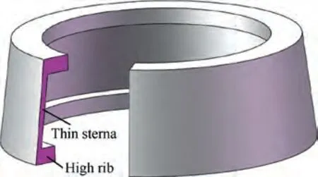
Fig. 1 Geometry of CRTSHR.
Traditional ring rolling (TRR) is an advanced incremental local forming process for manufacturing high-performance ring parts, during which ring produce the deformation of wall thickness decrement and diameter increment by the joint pressing of driven roll, idle roll and guide rolls,as shown in Fig. 2. Due to high processing performance and high processing precision, TRR has been widely applied to manufacture critical load-bearing ring parts of aerospace equipment, such as supporting frame,end frame and transition ring.To date,scholars have conducted many researches on analytical modeling,process simulation and microstructure characterization for TRR of rings.
Through analytical modeling, Berti et al put forward the conditions of two pairs of rolls successfully biting into ring for ring smoothly rotating during TRR.Quagliato et al.established a mathematical model to calculate the strain distribution in rolled ring during TRR. To make deformation in thickness and height directions more uniform during TRR,Qian et al.found the penetrating conditions of deformation region by mechanical modeling. To make ring diameter stably enlarge, Hua et al.found the critical condition of ring instability during TRR by mechanical modeling. Using the upper bound method,Parvizi and Abriniaestablished a mechanical model for accurately predicting the rolling force during TRR.By mathematical modeling, Li et al.determined the proper feeding strategy of idle roll during TRR of profiled ring so as to improve the forming precision of profiled ring.
Through the FE simulation, Yea et al.revealed the change rules of rolling force in TRR of plain rings and Tshaped rings. Zhou et al.investigated the influence of roll dimension on the deformation behaviors in hot TRR of large ring using a 3D thermo-mechanical coupling FE model. Lohmar et al.found that constraint rolls influence ring temperature in hot TRR of IN718 ring, and this effect can be eliminated by reasonably shortening rolling time and transferring time.Liang et al.achieved an intellective numerical simulation for controlling the real-time temperature of ring during hot TRR. Hua et al.investigated the material flow laws in cold TRR of L-profiled ring and found the conditions of stable rolling. For improving the forming precision of T-shaped rings, Kang et al.obtained the preferred ring blank for TRR by simulation. Based on the FE simulation, Oh et al.found some macro defects like folding and cavity underfilling during TRR of L-section ring and analyzed the cause of these defects.
Through characterizing the microstructure of rolled rings,Guo et al.investigated the improving mechanism of the mechanical property of 2219 Al-Cu Al alloy ring processed by warm and hot TRR. He et al.systematically investigated the microstructure evolution mechanism in warm and hot TRR of 2219 Al-Cu Al alloy ring. Guo et al.investigated the minimum amount of grain refinement in hot TRR of GCr15 steel bearing.Tang et al.analyzed the evolution rules of microstructure in TRR of IN718 ring using a microstructure prediction model.Ryttberg et al.revealed the evolution laws of microstructure in cold TRR of 100Cr6 steel ring.Yu et al.characterized the microstructure and performance of Magnesium alloy ring formed by hot TRR. Via microstructure characterization,Zeng et al.revealed the variation mechanism of the mechanical property of Magnesium alloy ring formed by hot TRR.
Summarily, the existing investigations mainly concentrated on TRR of plain rings and profiled rings, and no research on TRR of CRTSHR is reported.In fact,TRR is not suitable for manufacturing CRTSHR. Because ring diameter enlargement is not adequately constrained during TRR of CRTSHR, the plastic instability easily occurs to induce the poor roundness of CRTSHR, and ring diameter enlargement greatly goes against the forming of high ribs. On the other hand, because the speed of diameter enlargement in the height direction is inconsistent during TRR of CRTSHR, the shrinkage defect inevitably occurs at the bottom of ribs.
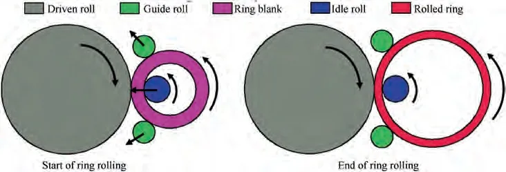
Fig. 2 Principle of traditional ring rolling.
Aimed at the above problem, an innovative constraining ring rolling process(CRR)is proposed in this paper to achieve the near-net-shape manufacturing of CRTSHR. To evaluate the proposed CRR and reveal its deformation behaviors, a thermomechanical coupled FE model for CRR of CRTSHR is established.Then,the experiment for CRR of CRTSHR is performed on a modified ring rolling machine, which proves that CRR of CRTSHR is feasible and the established FE model is reliable. Based on the reliable FE model, the metal flow mode in deformed CRTSHR is analyzed, and the deformation characteristics such as the stress state, strain distribution and the evolution of power parameters in CRR of CRTSHR are revealed.Finally,the influences of key factors such as the friction factor between ring and molds, the diameter of idle roll and the feed velocity of idle roll on CRR of CRTSHR are investigated by FE simulation.
2. Principle and advantages for CRR of CRTSHR
The principle for CRR of CRTSHR is shown in Fig. 3.In the preparation stage,the constraint roll tightly wraps the external conical surface of conical ring blank, and the end surfaces of constraint roll is coincided with the end surfaces of conical ring blank. Meanwhile, the idle roll contacts the inner conical surface of conical ring blank, and the two blocks respectively tightly press the two ends of constraint roll. In the rolling stage, the rotations of constraint roll, conical ring blank and two blocks are actively driven as well as the radial feeding of idle roll, and the rotation of idle roll is passively driven. Via the constraint roll and two blocks, the height and outer diameter of ring are fully restrained to increase, and thus the metal mainly flows radially to reduce sterna thickness and flows axially to form high transverse ribs on the internal conical surface of CRTSHR.In the finished stage,the idle roll firstly gets away from the rolled CRTSHR and other molds,and then the lower block gets away from the constraint roll. Consequently, the rolled CRTSHR can be smoothly taken out from the large end of constraint roll. Because of the unique principle, CRR has the following advantages: (1) because the constraint roll fully restrains the external conical surface of conical ring, it is pretty difficult for thin-walled ring with low stiffness to produce plastic instability. Thus, the whole rolling process is stable during CRR of thin-walled ring and the rolled ring has good roundness; (2) CRR is applicable to roll various thin-walled rings with complicated section.
3. FE modelling for CRR of CRTSHR
The approach of FE simulation is adopted in this work to verify the feasibility of CRR and investigate the deformation behaviors in CRR of CRTSHR. In the DEFROM-3D software platform, a thermomechanical coupled FE model for CRR of CRTSHR is set up, as described in Fig. 4. Since this work just concentrates on the feasibility and deformation behaviors for CRR of CRTSHR, the material of CRTSHR is not strictly limited. Hence, AA1050 aluminum is chosen as the material of CRTSHR in simulation,and its physical properties can be found in the previous literature.Considering that the strain-induced hardening for AA1050 aluminum at high temperature is not obvious, the peak stresses of AA1050 aluminum under the hot deformation condition can be used to predict the flow stresses in CRR of CRTSHR.The constitutive model of AA1050 aluminum is expressed as.˙ε=8095.53σexp -0.00819T
( ) (1)where σ refers to the peak stress, ˙ε refers to the strain rate and T refers to the absolute deformation temperature.Considering that the elastic deformation is far smaller than the plastic deformation in CRR of CRTSHR, the elastic deformation can be ignored and the rigid-plastic material model is adopted.All molds are defined as rigid bodies,and conical ring blank is defined as rigid-plastic body.In view of the research on the hot forming of Al alloy,the constant shear friction model is adopted and the friction factor between conical ring blank and molds is set as 0.3. Besides, the heat transferring coefficient between conical ring blank and molds is 11 N/s/mm/C,and the heat emitting coefficient between the deformable/rigid body and the air is 0.02 N/s/mm/C. To guarantee the simulation accuracy, some measures are taken as follows: (1) conical ring blank is divided into 230 thousand tetrahedral grids, and the dimension of meshes is within 0.3-0.6 mm;(2)the junctions of sterna and two transverse ribs are smoothed by a circular arc with 1.5 mm in radius for avoiding the severe distortion of meshes here; (3) the automatically remeshing function is enabled to address the distorted meshes in simulation, and the volume constancy criterion for conical ring blank is adopted to avoid the volume loss in mesh reconstruction.Some parameters used for the FE simulation are listed in Table. 1.
4.Validation of the established FE model for CRR of CRTSHR
To validate the reliability of the established FE model,several groups of experiments for CRR of CRTSHR are carried out on a modified D51-350 TRR machine. Process parameters,conical ring blank and the geometric parameters of working surfaces of molds in experiments are the same as that in simulation. In experiments, the surfaces of conical ring blank are coated with the MoSlubricant so as to reduce the friction force between ring and molds. On modified D51-350 TRR machine, the great friction force and great normal stress are produced between the driven roll and constraint roll via the rotation and feed of driven roll, which makes the constraint roll passively rotate and feed. Meanwhile, the idle roll doesn’t feed but just passively rotates under the action of friction force. When the constraint roll feeds for its target amount,the constraint roll stops feeding but keeps rotating for one circle at least to guarantee the roundness of the inner conical surface of CRTSHR.
Fig.5 shows that with the increase of thickness reduction in experiments,two transverse ribs on the inner conical surface of deformed CRTSHR gradually grow while the outer diameter and axial height of deformed CRTSHR keep unchanged.Fig. 6 shows the comparison of the height of two ribs on the deformed CRTSHR between simulation results and experimental results. The simulation results are in good accordance with the experimental results and the maximum error among them is 5.8%. The generated error may be ascribed to some factors,such as the different friction conditions between simulation and experiment and the elastic deformation of molds produced in experiments. Fig. 7 shows the comparison of the axial section shape of rolled CRTSHR between simulation results and experimental results. It can be observed from Fig. 7 that the axial section shape of rolled CRTSHR in simulation is basically the same as that in experiment. The above analysis demonstrates that the established FE model is reliable.Moreover, the sterna of CRTSHR is successfully rolled from 6 mm to 3 mm and rib height reaches 11.2 mm,and the rolled CRTSHR has good roundness. In contrast to TRR of CRTSHR,CRR of CRTSHR shows the following advantages:(1)the rolled CRTSHR can obtain better surface quality(good roundness and no shrinkage occurring); (2) thin-walled rings with high ribs can be stably rolled. This illustrates that CRR has great potential in manufacturing high-performance CRTSHR.

Fig. 3 Principle for CRR of CRTSHR.

Fig. 4 Established FE model for CRR of CRTSHR.
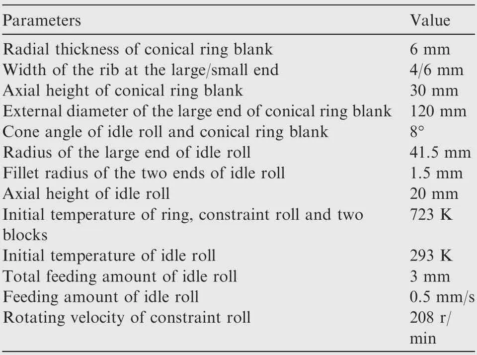
Table 1 Some parameters used for the FE simulation.
5. Results and discussion
5.1. Metal flow rules during CRR of CRTSHR
5.1.1. Metal flow rules along the axial direction
It should be noted that in this section the widths of two ribs are identical and they are 5 mm in simulation, and the other parameters are given in Table. 1. Fig. 8 shows the metal flow rules along the axial direction during CRR of CRTSHR, in which the orange zone denotes the axial section of deformed CRTSHR and the green arrows denote the axial flow velocity of the metal. As exhibited in Fig. 8, there exists two deformation zones in the sterna where the metal flow velocities are exactly opposite,and the interface between these two deformation zones is the axial divided-flow plane(labeled with the blue dotted lines).During CRR of CRTSHR,the axial divided-flow plane just slightly fluctuates around the middle plane (the distances from the middle plane to the two ends of deformed CRTSHR are identical), which makes the volume ratio of the metal flowing toward the two ends continuously variate.The slight fluctuation of the axial divided-flow plane illustrates that there exists mutual competition and restraint between the two ribs in their growth process.As shown in Fig.9,although the growth of the rib at the small end is still faster than that of the rib at the large end, the maximum height difference between the two ribs is less than 1.1 mm during CRR of CRTSHR, which means that the two ribs almost synchronously grow in CRR of CRTSHR.

Fig. 5 Deformed CRTSHR when thickness reduction is different in experiments.
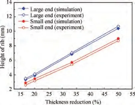
Fig.6 Comparison of height of two transverse ribs on deformed CRTSHR between simulation results and experimental results.
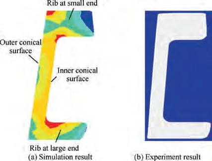
Fig. 7 Comparison of axial section shape of rolled CRTSHR between simulation results and experimental results.
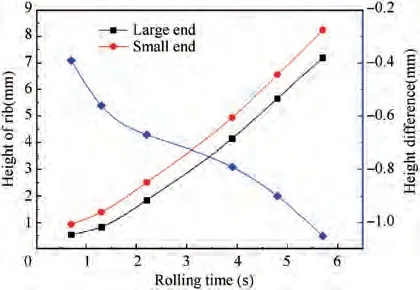
Fig. 9 Height variation of two ribs during CRR of CRTSHR.
It is well known that the axial divided-flow plane is influenced by the difference between the axial flow resistances at the two ends,i.e.,the axial divided-flow plane would be closer to the end where the axial flow resistance is larger.In order to reveal the variation mechanism of the axial divided-flow plane during CRR of CRTSHR,the variation rules of the axial flow resistances at the two ends should be clarified. The axial flow resistance at the small end is expressed by the axial stress at the midpoint of the interface I, and the axial flow resistance at the large end is expressed by the axial stress at the midpoint of the interface II(the interfaces I and II in the axial section are shown in Fig. 9). As shown in Fig. 10, in the initial rolling stage, the axial flow resistance at the large end is greater than that at the small end,because the metal flow velocity variation at the corner of the large end is greater than that at the small end. Therefore, the axial divided-flow plane is below the middle plane and closer to the large end, resulting in that more metal flows toward the small end. On the other hand, the diameter of the small end is smaller than that of the large end, so it is required that more metal flows toward the large end to guarantee that the two ribs grow into the same height.For the above two causes, the growth of the rib at the small end is slightly faster than that of the rib at the large end in the initial rolling stage, but the height difference between the two ribs is very small and the two ribs almost synchronously grow. With the growth of two ribs, the back pressures at the two ends naturally generated from the growth of ribs gradually increase. The back pressures at the two ends are proportional to rib height and inversely proportional to the contact length between the sterna and idle roll. Notably, the contact length between the sterna and the large end of idle roll is larger than that between the sterna and the small end of idle roll while the

Fig. 8 Variation of axial section shape of deformed CRTSHR during CRR.

Fig. 10 Variation of axial flow resistances at interfaces I and II during CRR of CRTSHR.
heights of two ribs are almost identical. Thus, the back pressure at the small end is larger than that at the large end, and the difference between the back pressures at the two ends gradually increases.However,the metal flow resistance at the large end is still larger than that at the small end,and the difference between them gradually decreases. This is because that the axial flow resistance at the two ends is the sum of back pressure and axial flow resistance merely induced by the two corners,and the difference between the axial flow resistances merely induced by the two corners remains unchanged and its value is larger than the difference between the back pressures at the two ends. As the difference between the axial flow resistances at the two ends decreases, the axial divided-flow plane gradually moves upward. Therefore, the amount of the metal flowing toward the small end is gradually reduced while the rib at the small end still grows faster than the rib at the large end, due to the diameter difference between the two ends.However, with the further decrease of the difference between the metal flow resistances at the two ends, the axial dividedflow plane begins to move downward after the idle roll feeds for about 1.2 mm,which may be induced by the weaken sensitivity of the axial divided-flow plane to the variation of the difference between the metal flow resistances at the two ends.Consequently, the height difference between the two ribs continuously enlarges slightly.
5.1.2. Metal flow rules along the tangential direction
To investigate the metal flow behavior along the tangential direction during CRR of CRTSHR, section A-A is selected along the middle plane of deformed CRTSHR and the velocity field distribution of deformation zone is presented in Fig.11.It is shown that under the action of idle roll and constraint roll,the metal in the deformation zone also tangentially flows toward the non-deformation zones (including the entrance zone and the exit zone). Due to special contact mode between the idle roll and deformed CRTSHR,the metal in the deformation zone mainly flows toward the entrance zone, which leads to local metal accumulation at the entrance zone as shown in Fig. 12. It can be seen from Fig. 12 that in the stable rolling stage (2.1-5.1 s), the degree of metal accumulation gradually increases as the idle roll radially feeds. This is because that the resistances of metal flowing axially at the two ends remarkedly increase with the growth of two ribs while the resistance of metal flowing tangentially basically remains unchanged,which causes that the amount of the metal flowing tangentially increases and the amount of the metal flowing axially decreases.However,in the finishing stage,the amount of metal accumulation gradually decreases with the feed of idle roll.This is because that the idle roll feeds no longer in the finishing stage, and the accumulated metal gradually flows toward the two ribs.
5.1.3. Displacement history of the metal at different positions
To qualitatively reveal the metal flow behaviors at different positions during CRR of CRTSHR, three critical tracking points A, B and C, respectively located at the large end, the middle plane and the small end of the axial section of conical ring blank as shown in Fig. 13(a), are selected to acquire their displacements along the axial direction (AD), the tangential direction(TD)and the radial direction(RD).Fig.13(b)shows that during CRR of CRTSHR the radial displacement of the metal at the two ribs is far greater than that of the metal at the sterna, and the displacement directions of them are just inverse, owing to the special contact mode of idle roll and deformed CRTSHR. Fig. 13(c) shows that the tangential displacement of the metal at the two ribs is almost zero, because the metal at the two ribs mainly flows radially to increase rib height. However, the tangential displacement of the metal at the sterna markedly increases with the feed of idle roll,because the great friction force between the idle roll and deformed CRTSHR drags metal to tangentially flow. Fig. 13(d) shows that the axial displacement of the metal around the middle plane is far smaller than its tangential displacement, because at this position the resistance of metal flowing axially is far larger than that of metal flowing tangentially.Moreover,the axial displacement of the metal at the two ends is almost zero,due to the axial constraint of two blocks.In summary,during CRR of CRTSHR, the metal at the two ends mainly flows radially to make ribs grow,and the metal at the sterna mainly flows along the tangential and axial directions to produce tangential and axial strains.
5.2. Deformation characteristics during CRR of CRTSHR
5.2.1. Stress distribution at the deformation zone
Fig.14 shows the distribution rules of three-directional stresses at the deformation zone in the axial section of deformed CRTSHR when the idle roll feeds for 2 mm. It is found that the compressive stresses in the radial, tangential and axial directions are unevenly distributed at the deformation zone.At the sterna, the absolute value of three-directional stresses mainly presents a decreasing tendency from the internal surface to the outer surface or from the middle plane to the two ends. This is because that on one hand, the contact area between the idle roll and sterna is smaller than that between the constraint roll and sterna,resulting in the increase of stresses from the outer surface to internal surface. On the other hand, the metal flow resistance at the middle plane is larger than that at the two ends, resulting in the decrease of stresses from the middle plane to the two ends. At the two ribs, the absolute value of three-directional stresses mainly presents a decreasing tendency in the radial direction from the bottom to the top of two ribs, because the metal flow resistance gradually decreases along this direction.Besides,the absolute value of three-directional stresses mainly gradually decreases in the axial direction from the side nearing the idle roll to the side nearing the blocks, because the contact area between the idle roll and rib is smaller than that between the block and rib.Consequently, the metal nearing the idle roll at the two ribs firstly reaches the yield condition and produce plastic deformation, and thus the growth of the side of two ribs nearing the idle roll is relatively fast,resulting in the varied inner diameter of two ribs in the axial direction as shown in Fig.14.Notably,the distribution of stresses at the region above the middle plane is not the same as the distribution of stresses at the region below the middle plane.This is because in one aspect,the varied diameter of the sterna in the axial direction causes that the distribution of stresses at the two sides of the middle plane is not symmetrical. In another aspect, the variation degree of metal flow velocity at the two corners is different, leading to the different distribution of stresses at the two corners.
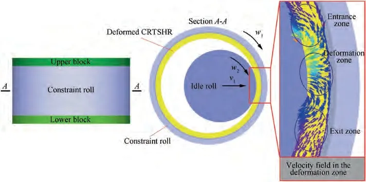
Fig. 11 Velocity field on section A-A in CRR of CRTSHR.
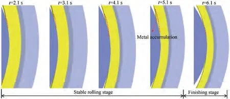
Fig. 12 Local metal accumulation induced by metal tangentially flowing in section A-A during CRR of CRTSHR.
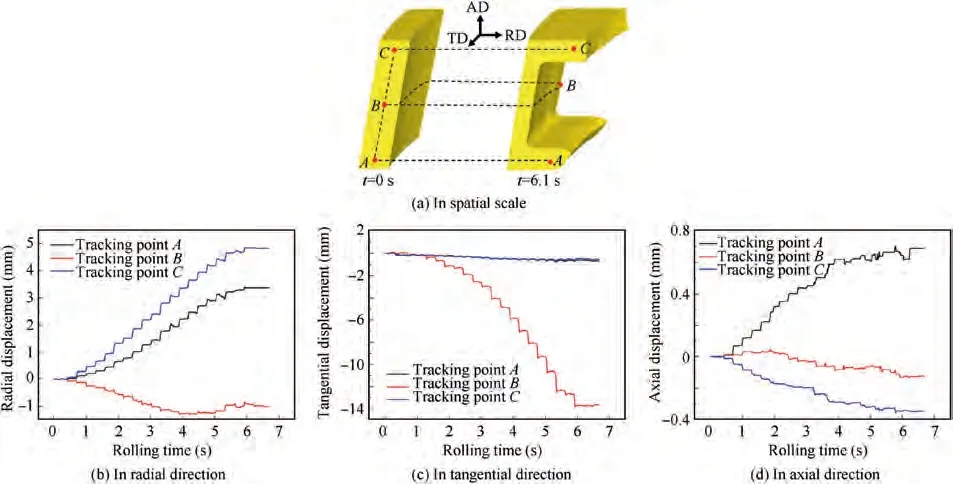
Fig. 13 Displacement histories of tracking points at different positions during CRR of CRTSHR.
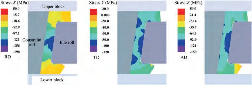
Fig. 14 Stress distribution at deformation zone in axial section of deformed CRTSHR.
5.2.2. Evolution characteristics of plastic deformation zone
Figs. 15 and 16 respectively show the distribution of effective plastic strain in the entire deformed CRTSHR and its axial section. It is illustrated that in the initial rolling stage (0-0.45 s),conical ring blank gradually bites into the gap between the constraint roll and idle roll,and the metal around the contact zone between the sterna and idle roll firstly produce plastic deformation, because the contact stress gradually decreases from the internal surface to the outer surface of the sterna.With the feed of idle roll, the rolling process gradually enters the stable state, and the plastic deformation zone gradually extends along the radial and circumferential directions. When the rolling time reaches 0.8 s,the entire thickness at the contact zone between the sterna and idle roll is nearly in the plastic deformation status, while the two corners are not completely in the plastic deformation status and there exists nondeformation zone as shown in Fig. 16. Meanwhile, the height of two ribs gradually increases with the feed of idle roll, and thus the back pressure at the two ends rapidly increases,which makes the metal flow resistances at the two ends rapidly increases. Therefore, the stresses in the non-deformation zone also rapidly increases and the metal here gradually reaches plastic deformation status, resulting in that the area of nondeformation zone gradually decreases. When the rolling time reaches 4.0 s, the plastic deformation zone has basically penetrated the entire deformed CRTSHR and non-deformation zone disappears. Overall, the effective plastic strain distribution in the circumferential direction is relatively homogenous while it is extremely inhomogeneous in the radial and axial directions.
5.2.3. Strain evolution history during CRR of CRTSHR
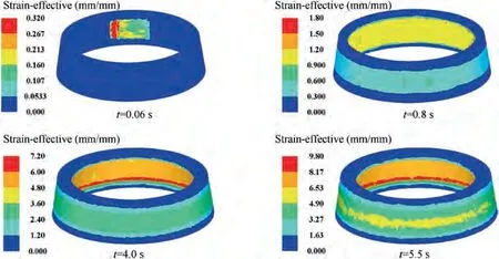
Fig. 15 Effective plastic strain distribution in entire deformed CRTSHR at different rolling time.

Fig. 16 Effective plastic strain distribution in axial section of deformed CRTSHR at different rolling time.
To investigate the evolution histories of strains at different positions during CRR of CRTSHR, three critical tracking points A,B and C as shown in Fig.13(a)are selected to acquire their strains along three principal directions. Fig. 17 shows that three-directional strains in the deformed CRTSHR increase stepwise,because CRR of CRTSHR is an incremental local forming process. Fig. 17(a) shows that during CRR the radial tensile strain is produced at the two ribs while the radial compressive strain is produced at the sterna. Fig. 17(b) shows that the tangential tensile strain is produced at the sterna while the two ribs just produce small compressive strain in the tangential direction. Fig. 17(c) shows that the axial tensile strain is produced at the sterna while the axial compressive strain is produced at the two ribs.It can be also seen from Fig.17 that three-directional strains increase stepwise at tracking points A and C before the rolling time reaches 3.7 s,and only the radial strain continuously increases while the tangential and axial strains keep unchanged after the rolling time reaches 3.7 s. It is because that tracking points A and C still locate at the two corners where three-directional strains are produced before the rolling time reaches 3.7 s.However,after the rolling time reaches 3.7 s,tracking points A and C have moved to the two ribs where only the radial shear deformation is produced.From the basic deformation rules described above, it can be concluded that during CRR of CRTSHR, the sterna mainly produces radial compressive strain, tangential tensile strain and axial tensile strain.The two corners mainly produce radial tensile strain and axial compressive strain,and the two ribs just produce radial shear deformation.
5.3. Distribution rules of strains in the deformed CRTSHR
Due to the nonlinearity of geometry and material,the distribution and evolution of stresses in the deformed CRTSHR are complicated during CRR, which makes the deformed CRTSHR produce inhomogeneous deformation. To reveal the deformation rules in the rolled CRTSHR, several critical feature points are selected to obtain the distribution rules of strains in the rolled CRTSHR, as shown in Fig. 18.
5.3.1. Distribution rules of strains at the large end
Fig. 19(a) shows that at the large end of rolled CRTSHR, the effective plastic strain gradually increases in the radial direction from the outer surface of the sterna to the interface between the sterna and the rib of the large end (the interface is drawn with the dotted line in Fig.19),because the stress concentration in the vicinity of this interface makes the effective plastic strain at the corner of the large end (the region in the left of the dotted line in Fig.19)gradually increase with reducing the distance from this interface. However, the effective plastic strain gradually decreases in the radial direction from this interface to the circumferential surface of the rib at the large end, because the circumferential surface of the rib at the large end has the smallest metal flow resistance and thus the deformation here is the smallest. Moreover, the effective plastic strain at the rib of the large end(the region in the right of the dotted line in Fig. 19) gradually increases in the axial direction from the side contacting the lower block to the side contacting the idle roll,because the side contacting the idle roll more early enters the plastic deformation status as discussed in Section 5.2.Fig.19(b)and(c)show that the axial and tangential strains at the rib of the large end have the same distribution rules with the effective plastic strain in the radial direction.Fig. 19(d) shows that the radial strain at the rib of the large end firstly increases and then decreases in the radial direction from the interface to the circumferential surface of the rib at the large end. However, the distributions of three-directional strains at the corner of the large end are irregular in the axial and radial directions,which may be caused by the complicated stress state at this position.

Fig. 17 Evolution histories of strains in CRR of CRTSHR.
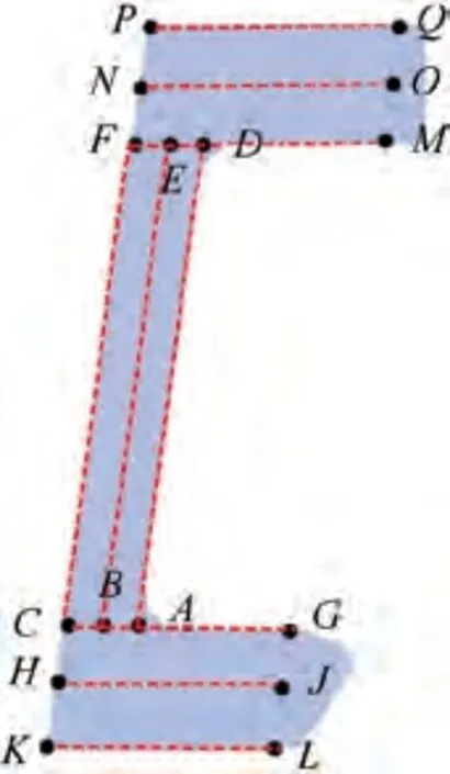
Fig. 18 Selection of feature points in axial section of rolled CRTSHR.
5.3.2. Distribution rules of strains at the sterna
Fig. 20(a) shows that at the sterna of rolled CRTSHR, the effective plastic strain gradually decreases in the radial direction from the internal surface to the outer surface of the sterna,because the metal nearing the internal surface more early enters the plastic deformation status. Besides, at the region nearing the outer surface of the sterna, the effective plastic strain firstly increases in the axial direction from the rib at the large end to the middle plane(the dotted line in Fig.20 represents the middle plane),and then it gradually decreases from the middle plane to the rib at the small end. It is because that during CRR of CRTSHR the metal at the two sides of the middle plane respectively flows upward and flows downward,and thus the deformation at the middle plane is the largest.However, on the internal surface of the sterna, the effective plastic strain around the two ends is the largest, because these positions show stress concentration and produce severe deformation. As shown in Fig. 20(b)-(d), the tangential tensile strain, radial compressive strain and axial compressive strain are produced at the two ends of the sterna,because these positions are close to the two corners where metal flow is complicated. Fig. 20(b) shows that the radial strain gradually increases in the radial direction from the outer surface to the internal surface of the sterna, which has been reflected in Fig.16.Apart from the two ends of the sterna,the radial strain basically slightly decreases in the axial direction from the region nearing the large end to the region nearing the small end,because the varied diameter of the sterna induces different deformation state in the axial direction. Fig. 20(c) and (d)shows that apart from the two ends of the sterna, as the distance from the middle plane decreases, the tangential strain gradually decreases while the axial strain gradually increases in the axial direction.
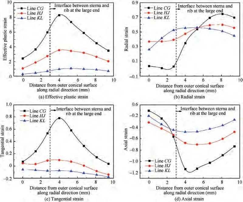
Fig. 19 Distribution rules of strains at large end of rolled CRTSHR.
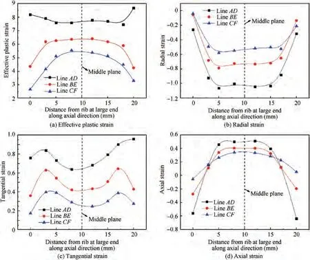
Fig. 20 Distribution rules of strains at sterna of rolled CRTSHR.
5.3.3. Distribution rules of strains at the small end
Fig. 21(a)shows that at the small end of rolled CRTSHR, the effective plastic strain at the region nearing the end contacting the idle roll gradually increases in the radial direction from the outer surface of the sterna to the interface between the sterna and the rib of the small end (the interface is drawn with the dotted line in Fig. 21), and then it gradually decreases from this interface to the circumferential surface of the rib at the small end. It is because that the stress concentration around this interface causes that the effective plastic strain is the largest at the corner of the small end(the left region of the dotted line in Fig.21).However,the effective plastic strain at the top side of the rib exhibits a decreasing trend in the radial direction from the outer surface of the sterna to the circumferential surface of the rib at the small end, which may be caused by the complicated metal flow at the corner of the small end. Moreover, the effective plastic strain at the small end gradually increases in the axial direction from the side contacting the upper block to the side contacting the idle roll,because the side contacting the idle roll more early enters the plastic deformation status. Fig. 21(b) and (c) show that the axial strain and tangential strain at the rib of the small end (the right region of the dotted line in Fig. 21) have the same distribution rules with the effective plastic strain in the radial and axial directions. Fig. 21(d) shows that the radial strain at the side contacting the upper block gradually decreases in the radial direction from the outer surface of the sterna to the circumferential surface of the rib at the small end. However, the radial strain at the side contacting the idle roll gradually increases in the radial direction from the outer surface of the sterna to the circumferential surface of the rib at the small end, while the radial strain at the medium of the rib just slightly fluctuates and basically remains unchanged in the radial direction.Notably,the distribution of three-directional strains at the corner of the small end is irregular in the axial and radial directions,which may be attributed to the complicated stress state at this position.
5.4. Evolution characteristics of power parameters
Fig.22 shows that the evolution histories of power parameters during CRR of CRTSHR.As shown in Fig.22(a),in the initial rolling stage (0 s to 0.45 s), the radial rolling force rapidly increases, owing to conical ring blank rapidly biting into the gap between the constraint roll and idle roll.In the stable rolling stage (0.45 s to 5.2 s), the radial rolling force slowly increases, which can be attributed to two aspects. On one hand,both temperature reduction and deformation accumulation make material yield strength slightly increase during CRR of CRTSHR. On the other hand, the height of two ribs gradually increases with the feed of idle roll,and thus the axial flow resistances at the two ends increase, which makes the stresses at the deformation zone increase. In the final rolling stage(5.2 s to 6.5 s), the idle roll stops feeding radially and the area of deformation zone rapidly decreases, resulting in that the radial rolling force rapidly decreases. Fig. 22(b) shows that the variation rules of the rolling torque and radial rolling force are basically uniform, because the rolling torque is positively related with the rolling force.
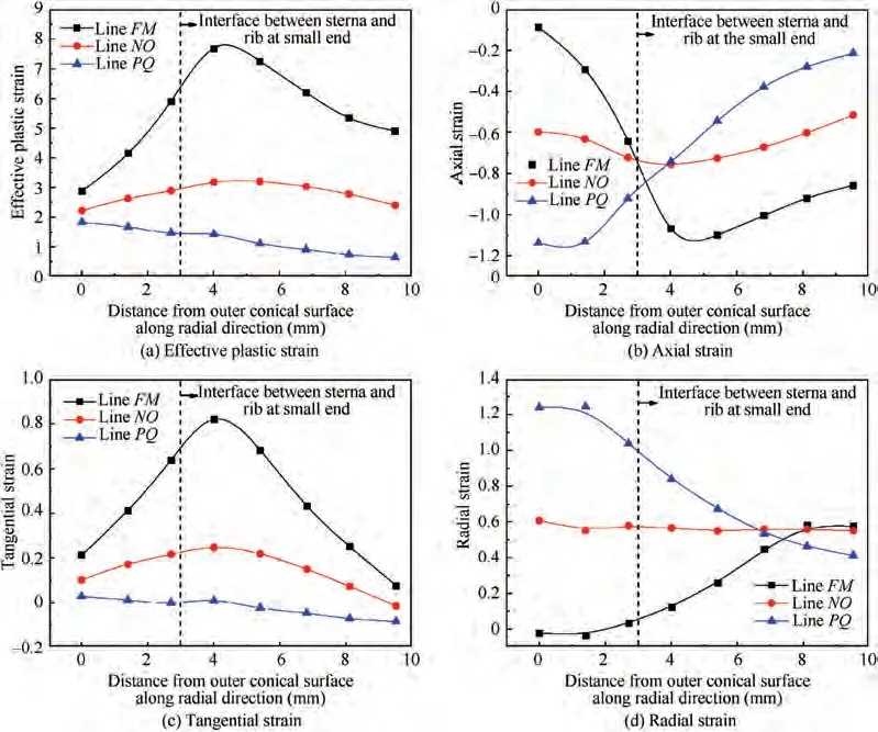
Fig. 21 Distribution rules of strains at small end of rolled CRTSHR.
Fig.22(c)shows that there exists axial forming force on the idle roll,and the direction of the integrated axial forming force on the idle roll is toward the large end.This is because that the area of deformation zone above the middle plane is smaller than that below the middle plane,and thus the axial flow resistance induced by the metal above the middle plane flowing upward is smaller than that induced by the metal below the middle plane flowing downward. Consequently, the evolution rules of the axial forming force on the idle roll is similar to that of the radial rolling force. However, the axial forming forces on the two blocks mainly firstly increase rapidly,then basically keep unchanged and finally rapidly decrease, as shown in Fig.22(c).It is because that in the stable rolling stage,the contact area between the sterna and block is rapidly reduced with the feed of idle roll and meanwhile the axial stresses on the two blocks rapidly increase with the growth of two ribs,which may lead to that the axial forming forces on the two blocks don’t increase with time but basically keep unchanged. The axial forming force on the upper block is larger than that on the lower block in the forming stage of 4.2-5.2 s, while the axial forming on the upper block is smaller than that on the lower block in the other forming stage. This is because that the growth competition of the two ribs induces the variation of the axial flow resistances at the two ends. Moreover, the axial forming forces on the two blocks are far larger than that on the idle roll, because the directions of the axial forming forces on the idle roll respectively induced by metal flowing upward and metal flowing downward are inverse and the difference between them is small. The radial rolling force on the idle roll is smaller than the axial forces on the two blocks in the forming stage of 0.45-2.5 s,while the radial rolling force on the idle roll is larger than the axial forming forces on the two blocks in the forming stage of 2.5-6.0 s,which can be attributed to complicated metal flow.
5.5. Effects of key parameters on CRR of CRTSHR
As discussed above, the complicated metal flow mode during CRR of CRTSHR induces inhomogeneous deformation and the irregular evolution of power parameters, which may be influenced by key parameters such as the friction coefficient,the diameter of idle roll and the feed velocity of idle roll. Via the established FE model, the effects of these parameters on the height of two ribs, inhomogeneous deformation degree and maximum rolling force when CRR of CRTSHR is finished are investigated. In this section, the widths of two ribs are 5 mm and key parameters are assigned different values according to Table.1 in simulation.Herein,based on Eq.(2)the standard deviation of effective plastic strain (SDE) can be calculated to evaluate the inhomogeneous deformation degree of rolled CRTSHR, and the larger value of SDE means that the deformation is more inhomogeneous.

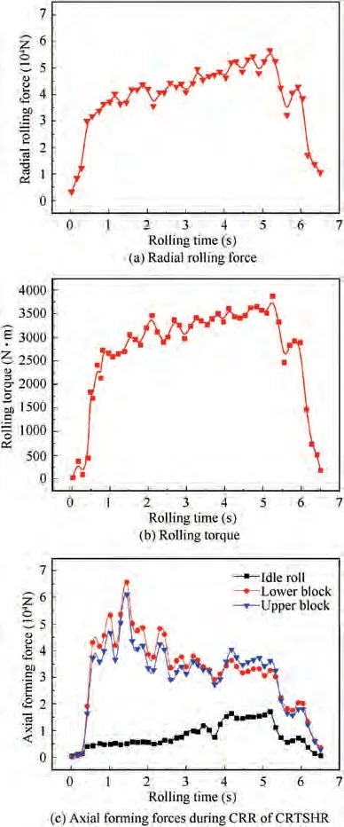
Fig. 22 Evolution histories of power parameters.

5.5.1. Effect of the friction factor on CRR of CRTSHR
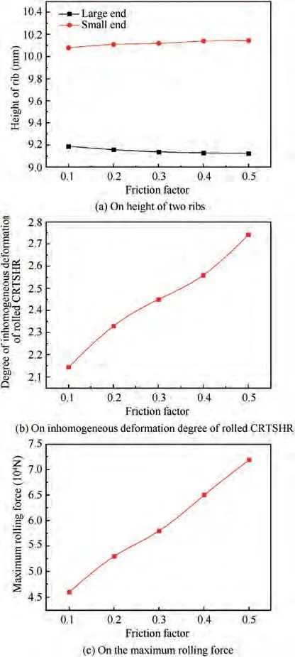
Fig. 23 Effects of friction factor on CRR of CRTSHR.
Fig. 23(a) shows that with the increase of the friction factor between conical ring blank and molds, the height of the rib at the large end slightly decreases while the height of the rib at the small end slightly increases, which illustrates that the height difference of two ribs gradually increases. This is because that the friction resistance generated from the relative slip between conical ring blank and molds in CRR of CRTSHR is positively related with the friction factor,and thus the difference between the metal flow resistances at the two corners gradually increases with the increase of the friction factor. This also means that with the increase of the friction factor, the metal flow resistance at the corner of the large end becomes larger in contrast to that at the corner of the small end and the axial divided-flow plane is closer to the large end. Consequently, more metal flows toward the small end,resulting in the enlarged height difference of two ribs.Fig. 23(b) shows that the inhomogeneous deformation degree gradually increases with the increase of the friction factor. It is because that increasing the friction factor reduces the penetration speed of plastic deformation zone in the radial direction, resulting in larger inhomogeneous deformation degree.Fig. 23(c) shows that the maximum rolling force almost linearly increases with the increase of the friction factor. It is because that with the increase of the friction factor, the metal flow resistance gradually increases, leading to the increased rolling force.
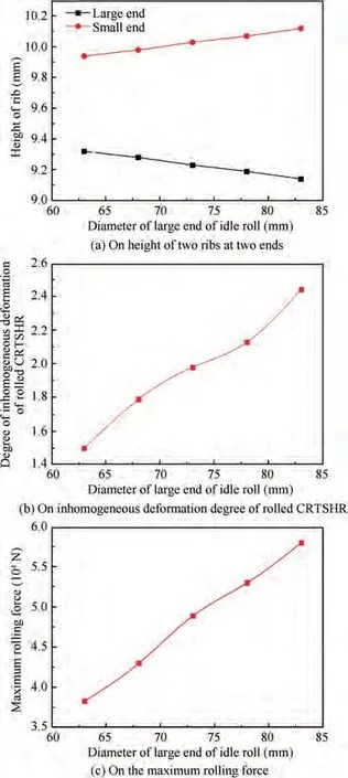
Fig. 24 Effects of diameter of large end of idle roll on CRR of CRTSHR.
5.5.2. Effect of the diameter of idle roll on CRR of CRTSHR
Fig. 24(a) shows that with the increase of the diameter of idle roll, the height of the rib at the large end gradually decreases while the height of the rib at the small end gradually increases.This is because that increasing the diameter of idle roll makes the contact arc length between the end of sterna and idle roll increases. However, only the radial shear deformation is produced at the two ends and the back pressure generated from the growth of two ribs is inversely related with the contact arc length between the end of sterna and idle roll. Thus, with the increase of contact arc length, the back pressures at the two ends gradually decreases and the difference between them also gradually decreases. Notably, the axial flow resistance at the two ends is the sum of the back pressure and the axial flow resistance merely induced by the two corners, and the difference between the axial flow resistances merely induced by the two corners remains unchanged and its value is larger than the difference between the back pressures at the two ends.Therefore, the difference between the axial flow resistances at the two ends increases and the axial divided-flow plane gradually approaches to the large end with increasing the diameter of idle roll. Consequently, more metal flows toward the small end, leading to the enlarged height difference of two ribs.Fig. 24(b) shows that the inhomogeneous deformation degree gradually increases with the increase of the diameter of idle roll, which is mainly caused by the variation of the axial divided-flow plane.Fig.24(c)shows that the maximum rolling force almost linearly increases with the increase of the diameter of idle roll.This is because that the area of plastic deformation zone gradually increases with increasing the diameter of idle roll, leading to the increased rolling force.
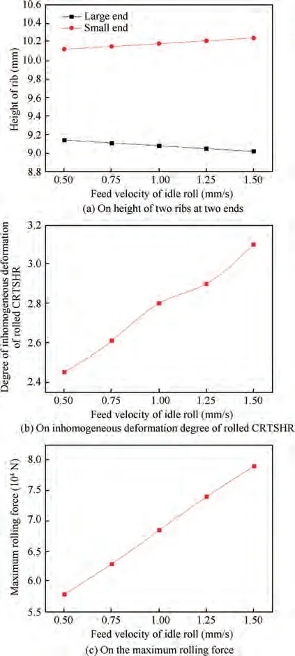
Fig.25 Effects of feed velocity of idle roll on CRR of CRTSHR.
5.5.3.Effect of the feed velocity of idle roll on CRR of CRTSHR
Fig. 25(a) shows that with the increase of the feed velocity of idle roll, the height of the rib at the large end gradually decreases while the height of the rib at the small end gradually increases. This is because that the contact arc length between the end of sterna and idle roll gradually increases with increasing the feed velocity of idle roll, resulting in that the axial divided-flow plane is closer to the large end. Fig. 25(b) shows that the inhomogeneous deformation degree gradually increases with the increase of the feed velocity of idle roll,which is mainly caused by the variation of the axial dividedflow plane. Fig. 25(c) shows that the maximum rolling force almost linearly increases with the increase of the feed velocity of idle roll, which can be attributed to two aspects. On one hand,the area of plastic deformation zone gradually increases with increasing the feed velocity of idle roll, leading to the increased rolling force.On the other hand,the strain rate obviously increases with increasing the feed velocity of idle roll,and thus the yield strength of ring material is enhanced, leading to the increased rolling force.
6. Conclusions
An innovative constraining ring rolling process (CRR) is proposed in this work to realize the near-net-shape forming of conical rings with thin sterna and high ribs (CRTSHR) used on aerospace equipment. Through the FE simulation and experiment, CRR of CRTSHR is proven to be feasible and the deformation behaviors in CRR of CRTSHR are investigated comprehensively. This research obtained the following findings:
(1) Through the proposed CRR,CRTSHR can obtain good forming quality,and the sterna of CRTSHR can be successfully rolled to 3 mm and the height of transverse ribs can reach 11.2 mm. It illustrates that CRR has great potential for manufacturing thin-walled rings with high ribs.
(2) During CRR of CRTSHR, the axial divided-flow plane in the axial section of deformed CRTSHR slightly fluctuates around the middle plane and the metal flow is complicated, leading to that the two ribs compete and restrain each other in their growth process. Besides,the metal at the sterna of CRTSHR mainly flows along the circumferential and axial directions,and the metal at the two ribs mainly flows along the radial direction.Consequently,the sterna produce compressive deformation in the radial direction and tensile deformation in the circumferential and axial directions while the two ribs just produce shear deformation in the radial direction.
(3) During CRR of CRTSHR, the deformation zone not only expands radially from the inner surface to the outer surface of the sterna but also expands axially from the middle plane to the two ends of the sterna. Consequently, the inner surfaces of two ribs are uneven, and the strains are regularly distributed at the sterna and two ribs while they are irregularly distributed at the junctions of the sterna and two ribs.
(4) The radial rolling force and axial forming force on the idle roll firstly increase rapidly, then slowly increase and finally decrease rapidly during CRR of CRTSHR.The axial forming forces on the two blocks mainly firstly increase rapidly, then basically keep unchanged and finally decrease rapidly. Because of the complicated metal flow mode, the radial rolling force on the idle roll is smaller than the axial forces on the two blocks in the forming stage of 0.45 s ~2.5 s while the radial rolling force of the idle roll is larger than the axial forces on the two blocks in the forming stage of 2.5 s ~6.0 s.The axial forming forces on the two blocks are far larger than that on the idle roll.
(5) The friction factor between ring and molds has influence on CRR of CRTSHR as well as the diameter and feed velocity of idle roll. With the increase of these parameters,the height difference of two ribs gradually increases as well as the inhomogeneous deformation degree and the maximum rolling force.
The authors declare that they have no known competing financial interests or personal relationships that could have appeared to influence the work reported in this paper.
The authors would like to thank the National Natural Science Foundation of China (No. U2037204), the Natural Science Foundation of Hubei Province (No. 2019CFA041), the National Key Research and Development Program of China(No.2019YFB1704502)and the Fundamental Research Funds for the Central Universities(No.2019-YB-016)for the support given to this research.
 Chinese Journal of Aeronautics2022年8期
- Chinese Journal of Aeronautics的其它文章
- Active, compact, wideband, receiving filtenna with power adaptation for space-limited wireless platforms
- Deployment of SMP Miura-ori sheet and its application: Aerodynamic drag and RCS reduction
- Beam tracking method based on reconfigurable intelligent surface for obstructed communication
- An alternative method to reduce process-induced deformation of CFRP by introducing prestresses
- Novel orbit-attitude combination mode for solar power satellites to reduce mass and fuel
- Synthetic damage effect assessment through evidential reasoning approach and neural fuzzy inference: Application in ship target
