Active, compact, wideband, receiving filtenna with power adaptation for space-limited wireless platforms
LI Dotong , YU Yqing , TANG Ming-Chun ,*, LI Djing , MU Dongmei ,LI Mei
a School of Microelectronics and Communication Engineering, Chongqing University, Chongqing 400044, China
b Institute of Wireless Mobile Information Technology, School of Electronic Engineering of Beijing University, Posts and Telecommunications, Beijing 100876, China
KeywordsActive filtenna;Amplifier;Compact;Power adaptation;VGA;Wideband
Abstract An active, compact, wideband, receiving filtenna with power adaptation for spacelimited wireless platforms is presented.By organically combining a filtering antenna and a Variable Gain Amplifier(VGA),the proposed co-designed active filtenna is achieved.Its power adaptation is empowered by controlling gain of the VGA unit.A demonstrated prototype with a compact overall size is fabricated,assembled and measured.Good performances are achieved.Furthermore, in any condition,the proposed active filtenna displays outstanding impedance matching(|S11|<-10 dB)and high passband skirt selectivity at upper and lower stopbands (Selectivity ≥170 dB/GHz).
1. Introduction
With the prosperous development of wireless communication systems,the antennas and filters in front-end of the communication system are indispensable componentsThe filtennas,multi-functional components combined with filters and radiators, have been developed, which can reduce the overall size and transmission losses between the filter and antenna.Recently, multifarious of filtennas have been reported to meet the limited space requirement at the wireless stages and to treat with the troublesome electromagnetic environments, because of their attractive out-of-band rejection performances.Among them, the active filtennas hold the radiation performance improvement and multi-function advantages than the passive ones. Consequently, various active filtennas have been reported.However, the reconfigurable filtennas cannot improve the radiation power densityand efficient filtennas has no functional reconfigurability.
Generally, in various space-limited, multi-system wireless platforms/scenarios,e.g.,submarines,tunnels,etc.,the signal strengths are weak and/or unstable,and the out-of-band interferences are strong.Therefore,both the high and adaptive gain and high-level stopband rejection to assure reliable signal sending in the working frequency band and prevent interferences from other communication systems are desired for communication systems.The above demands could be met by one radiator itself if it could possess the performances of efficient inband, excellent stopband suppression and dynamical power adaptation. Moreover, it correspondingly diminishes the design complexity and budget of the whole system. Therefore,it is anticipated to develop one active compact filtering antenna possessing both enhanced gain and dynamical power reconfigurability to solve the above cases.
A compact gain-agile filtenna with novel method to effectively combine the amplification function has been proposed in Ref. 9, but the analysis and operating mechanism in detail were not given.Based on the work of Ref.9,an extended active compact,wideband,power adaptive receiving filtenna for spacelimited wireless platforms is developed in this paper.In the Section 2,a passive planar filtenna,together with its corresponding equivalent circuit model and a Variable Gain Amplifier(VGA)circuit are,respectively introduced to prepare for designing the active filtenna.As described in Section 3,the active filtenna configuration is provided and its design parameters are detailed.The Simulation and measurement results are detailed in Section 4. The measured results demonstrate that, in the working frequency band of 860-1070 MHz, the active filtering antenna can obtain an average active gain ranging from 21.34 to-19.77 dBi.Finally,conclusions are drawn in Section 5.
2. Computation scheme design of compact passive filtenna and VGA circuit
2.1. Compact passive filtenna
Fig. 1 depicts the configuration of the compact passive filtenna,it consists of a square radiation patch and a capacitively coupled folded feeding strip composed of the T-shaped and the π-shaped strips associated using a metallic column,as shown in Figs. 1(a) and (b). The proposed passive filtenna consists of three square substrate layers that are labeled as Layer_1,Layer_2 and Layer_3, respectively. All substrates are Rogers RO4350with relative dielectric constant ε=3.66,loss tangent tan δ = 0.004 and dielectric thickness 1.524 mm. The air gaps between the layers are equal.
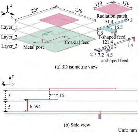
Fig. 1 Proposed passive filtenna configuration and its design parameters.
The Fig. 2(a) exhibits the corresponding equivalent circuit model of the proposed passive filtenna. The presence of the T-shaped section and the capacitive coupling between it and the square radiation patch can be equivalent to a series circuit of the inductor Land the capacitor C,which is labeled as ①.Similarly, the presence of the π-shaped section and the capacitive coupling between it and the square radiation patch can be equivalent to a series circuit of the inductor Land the capacitor C,which is labeled as ②.Moreover,the feeding resonator(i.e., the capacitively coupled folded feeding strip), and the square radiation patch can be modeled by the parallel LCand RLCcircuits, which are respectively marked as③and ④.The coupling between the two resonators is mainly contributed by the overlapped sections between the feeding strip and the radiation patch, which is similar to the parallelcoupled lines, and thus can be modeled by a J (admittance)inverter.
The|S|and|S|of the equivalent circuit,plotted in Fig.2(b), which match well with the return loss and the normalized realized gain value of the passive filtenna. It can be clearly observed that the passive filtenna operates in the range from 0.9 to 1.02 GHz. The bandwidth of the filtenna can be improved by adjusting the positions of the two transmission poles ③and ④. There are two Transmission Zeros (TZs)located at 0.495 and 1.335 GHz leading the high passband skirt selectivity values of 142 and 136 dB/GHz in the upper and lower stopbands, respectively.The selectivity of the passive filtenna can be improved by adjusting the positions of the two TZs. Moreover, the radiation efficiency is over 90%.
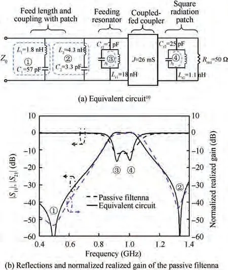
Fig. 2 Equivalent circuit and responses of the proposed passive filtenna.
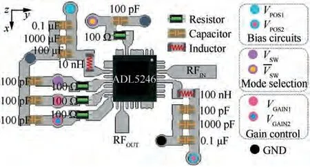
Fig. 3 Layout of the VGA circuit.
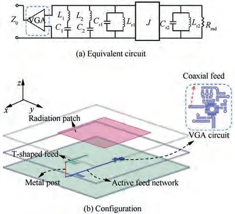
Fig. 4 Equivalent circuit and configuration of the proposed active filtenna.
2.2. VGA circuit
As a demonstration, the ADL5246 chip, a 50 Ohm internally matched RF amplifier which can provide high linearity performance over the 45 dB gain dynamic range was chosen to design the active VGA circuit.Fig.3 demonstrates the built VGA unit with a working frequency from 0.6 to 3 GHz. To achieve a wide gain variation range, the VGA high gain mode, accomplished by the collaboration of the logic low level Vand logic high level Vin the amplifier, is selected. In addition,the output gain value can be controlled by Vand Vports.Vand Vprovide bias voltages for the VGA circuit. The Radio Frequency (RF) chocks inductors and the capacitors are utilized.
3. Design the compact active filtenna with power adaptation
In this Section,the compact passive filtenna and the VGA circuit, which is to empower power adaptation of the filtenna,will be organically integrated as a single module to realize an active filtenna,which contains three functions,namely,receiving signal, selecting signal, and amplifying signal. It is worth mentioning that the integrating can reduce the insertion loss without increasing the overall size, thereby improving the transmission efficiency and intelligence of the receiving system.
Similar to the passive one in Fig.1,the geometry of the proposed active filtenna plotted in the bottom of the Fig.4 is composed of three layers of substrates. In the design, the active feeding network is located on the upper surface of Layer_3.In addition, the top of the Fig. 4 shows the corresponding equivalent circuit model of the active filtenna. It is worth noting that, compared with a passive filtenna cascaded with a VGA, the proposed active filtenna, which is implemented by integrating three discrete devices into a new compact codesign device utilizing a spatial three-dimensional structure,can not only greatly reduce the overall structure size, but also eliminate the connection losses between devices.
Furthermore, the configuration of the proposed active filtenna is simple and with a compact overall size, which is electrically smaller than most of recent reported passive patch filtennas.In detail,a comparison of the important specifications with recently reported planar filtennas is carried out and the results are summarized in Table 1.
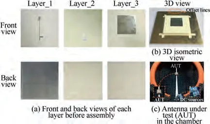
Fig. 5 Fabricated active filtenna with power adaption.

Table 1 Comparison of proposed filtenna with reported ones.
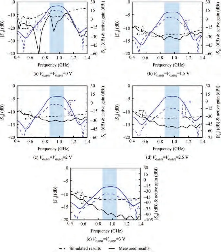
Fig.6 Simulated|S11|and|S21|of the equivalent circuit(dashed lines)and the measured|S11|and the active gain values of the proposed active filtenna (solid lines) at different voltage values of the VGAIN1 and VGAIN2 ports.
4. Simulation and measurement results
The active filtenna was designed, fabricated, assembled, and measured, and the photographs of the fabricated prototypes are shown in Fig. 5. The far-field radiation performance of the active filtenna was measured with a SG128 multi-probe antenna measurement system. The Antenna Under Test(AUT) in the measurement chamber is shown in Fig. 5(c)along with two regulated dc power supplies providing the requisite 0-5 V to turn on and adjust the VGA circuit. And the measurement results are demonstrated in Figs. 6 and 7.
First, the dashed lines in Fig. 6 are the simulated Sparameters of the equivalent circuit in Fig. 4. The solid lines in Fig.6 are the measured|S|and the active gains of the fabricated active filtenna at the selected five voltage values. The tested results of the active filtenna in all five cases, which are very consistent with the simulated results of its equivalent circuit, are well matched throughout the measured frequency band, as shown in Figs. 6(a)-(e). It is worth expounding that the |S| of the active filtenna is different from the |S| (in Fig.2)of the passive filtenna.As the|S|of the active filtenna only characterizes its ability to operate well within its operating band, its out-of-band rejection characteristics are reflected in the measured active gain results in corresponding five cases,as shown by the solid blue lines in Figs. 6(a)-(e). As a consequence, the simulated |S| shown in Fig. 6 is only the transmission coefficients of the VGA and filtering structure,without considering the realized gain response of the filtenna.In contrast, the measured active gain values for the active filtenna are determined by both the transmission coefficients of VGA and filtering structure, and the radiation characteristic of antenna. Therefore, there exist reasonable differences between the simulated |S| and measured active gain values in Fig. 6.
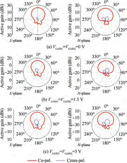
Fig. 7 Measured active gain patterns of the proposed filtenna working at 980 MHz with three different dc voltages.
With the voltage values of VGA altering from 0 V to 3 V,the corresponding average active gain value of the active filtenna range changes from 21.34 to -19.77 dBi within the pass-band 0.86-1.07 GHz.Thus,they further demonstrate that the VGA circuit has little influence on the operating bandwidth even though it has a large impact on their active gain values.In all cases,the active filtenna has good out-of-band rejection and the selectivity values of the upper and lower bands are higher than 170 dB/GHz. As anticipated, the measured active gain response is in accordance with the simulated |S| response.In summary,the proposed active filtenna holds the capabilities of dynamically adapting the receiving power that can improve the in-band active gains and the out-of-band rejection levels.Because of the high out-of-band rejection characteristic, the interference signals outside the passband, i.e., the other signal source can be suppressed deeply.
Fig. 7 plots the measured active gain patterns of the active filtenna with three specified different dc voltages.Note that,in all cases, the active filtenna shows high unidirectional radiations with measured Front-To-Back Ratios (FTBR) of 20 dB. Furthermore, low cross-polarization levels of 20 dB lower than the co-polarization levels in both E- and Hplanes are achieved, which indicate high polarization purity.It should be mentioned that the VGA circuit does not affect the radiation characteristics because the uniform and stable gain patterns in all cases are obtained.
5. Conclusions
An active, compact, wideband, receiving filtenna with power adaptation for space-limited wireless platforms was introduced in this paper. In the passband, the active filtenna shows excellent impedance matching; in the out-of-band, the high-level selectivity and stopband suppression are also achieved in all cases, which can significantly improve the anti-interference characteristic of the receiving system. Furthermore, by organically integrating a VGA circuit into the feeding strip of the passive filtenna, the active filtenna with power adaption characteristic and flat broadside average active gain range from 21.34 to -19.77 dBi is realized. Consequently, the antiinterference capability of the proposed active filtenna can be significantly enhanced. Due to the superiorities of compact volume, attractive band-pass filtering performance, and dynamical power adaption, there are many potential applications in various space-limited, multi-system wireless platforms with strong out-of-band interference and weak and/or unstable signal strengths.
The authors declare that they have no known competing financial interests or personal relationships that could have appeared to influence the work reported in this paper.
This study was co-supported by the National Natural Science Foundation of China(Nos.61801059 and 62031006),the Open Project of State Key Laboratory of Millimeter Waves, China(No. K202016) and the Chongqing Natural Science Foundation, China (Nos. cstc2019jcyj-msxmX0350 and cstc2019jcyjjqX0004).
