Beam tracking method based on reconfigurable intelligent surface for obstructed communication
Hongyao LI, Jianxiang XI, Ming HE, Xicong WANG
School of Missile Engineering, Rocket Force University of Engineering, Xi’an 710025, China
KEYWORDS Beam tracking;Obstacle;Phase shift;Reconfigurable intelligent surface;Unmanned aerial vehicle
Abstract This paper proposes a new reconfigurable intelligent surface based three-dimensional beam tracking method to solve the beam tracking problems for the unmanned aerial vehicle with obstacles in communication channels. The proposed beam tracking method can not only regulate the reconfigurable intelligent surfaces to achieve the beam tracking of the obstructed communications, but also optimize the transmission efficiency of the communication. Firstly, a reconfigurable intelligent surface is proposed,which can correlate the transmission signals by adjusting the phaseshift matrix. Meanwhile, a new communication channel is constructed according to the reconfigurable intelligent surface, which consists of two parts. The first one is the channel between the unmanned aerial vehicle and the reconfigurable intelligent surface,the other is the channel between the reconfigurable intelligent surface and the ground base station. Note that the transmission performance of the communications can be optimized by adjusting the phase shift of each uniform linear array on the reconfigurable intelligent surface. Then, a new beam tracking method for the unmanned aerial vehicle with obstructed communications is proposed on the basis of the reconfigurable intelligent surface.By proposing the mixed genetic algorithm,the estimation accuracy of the azimuth and elevation angles is improved to enhance the performance of the beam tracking.Finally,the simulations are provided to verify the effectiveness of the proposed three-dimensional beam tracking method with reconfigurable intelligent surface.
1. Introduction
In recent years,due to the fast development of the control and communication technologies, the Unmanned Aerial Vehicle(UAV) and UAV swarms have aroused many attentions from researchers,which is applied extensively in the rescue operation,the aerial imaging,the formation based on consensus,and the wireless communications,etc.Most of the above-mentioned applications are based on the Line-Of-Sight(LoS) transmission between the UAV and its serving Ground Base Station (GBS). It is critical to link the reliable and wide-range links between the UAV and the GBS in the coming 5G era reliably.A feasible method to implement the communication links was to backhaul quickly and integrate both UAVs and GBSs into the cellular network.Compared with the traditional communications, the new communication systems of UAV are distinct in terms of the unique channel characteristics of the UAV.As the new channel will suffer strong interference, the Three-Dimensional (3D) beamforming method was proposed to enhance the channel gain and mitigate the interference.
To improve the effect of beamforming gain,the variation of the channel from high mobility UAV has to be tracked for obtaining the accurate channel state information.In the forthcoming 5G era,the 3D beam tracking methods will draw a significant attention. Zhang et al. proposed a codebook-based beam tracking strategy for mobile millimeter-wave (mm-Wave) systems, where the temporal variation of the angle of departure was considered.Note that the proposed beam tracking method can achieve significant gains for both the slow-varying scenario and the fast-varying scenario, and the system with a pulse Doppler phased array radar was used to process multiple simultaneously received beams. Jang and Choi proposed a heuristic algorithm to minimize the multiple digital beams tracking time of the system in total.Also,Huang et al.proposed a new 3D beam tracking method based on the estimation of the angular speeds of UAV with the received pilots.
Due to the strong maneuverability of UAVs and the complicated environment, communications between the UAV and the GBS is often obstructed. And due to the significance of the communications between UAVs and GBSs, it is vital to investigate the communications of obstructed channel,and to report the significant and profound results. Choi studied the problem of obstructed communications in mm-Wave cellular system, where more unblocked GBSs and less outage probability can be realized by increasing the communication range.Note that the scale of the communication system is large and the cost is high while solving the obstructed communication problems. In Ref. 23, to exploit the directivity of the mm-Wave signal, the number and the precise location information of obstacles are needed for deploying the smart antennas at each obstacle, which leads to the high cost and low efficiency. It should be pointed out that the methods in Refs.22,23 are not suitable to solve the 3D beam tracking problem with obstructed communications. From the above analysis, it can be concluded that a low cost and high efficiency method for 3D beam tracking is significant to be investigated in the situation of the obstructed communications. To the best of our knowledge, this problem is still open and is challenging to be studied.
This paper studies the 3D beam tracking in the case of the obstructed communications. A new Reconfigurable Intelligent Surface (RIS) is constructed to achieve the 3D beam tracking of the UAV. A series of Uniform Linear Arrays (ULAs) are adopted to construct the RIS, where ULAs can receive and reflect transmission signals. According to the RIS, the obstructed channel can be described as the multiplying of two channels, that is, the channel between the UAV and the RIS, and the channel between the RIS and the GBS.Meanwhile, the phase-shift matrix of RIS is designed to adjust the reflection angles of ULAs such that the transmission channel among the sender, the transmission terminal and the receiver can realize coherent. Furthermore, a closed-loop control system is proposed for 3D beam tracking of UAVs, which can be realized by obtaining the predicted data of the azimuth and elevation angles without sending new pilots. Note that the closed-loop control system can guarantee the accuracy of the 3D beam tracking by accessing information about the UAV azimuth and elevation angles from time to time. The methods used to deal with the obstructed communications is still not comprehensively investigated and still open.
Compared with the existing related works about the 3D beam tracking, the contributions of this paper are as follows.Firstly, to solve the problem of 3D beam tracking with obstructed communications between UAV and GBS, an RIS consisted of ULAs is designed, which can re-establish new communication channels to connect with the GBS and UAV in a low-cost and high-efficiency way.It should be emphasized that the designed RIS can achieve the communications of obstructed channel by reflecting signals. However, the 3D beam tracking cannot be realized for obstructed communications in Ref. 21. The existing works in Refs. 22,23 can only solve the problems in terms of the obstructed communications with high cost and low efficiency.Secondly,compared with the traditional methods in Refs. 22,23, a phase-shift matrix is designed to describe the reflection angles of ULAs for the RIS,which can adaptively adjust to getting the coherent signal to enhance the transmission performance described by the achievable rate of the channel in total.Thirdly,compared with the Violent Search Algorithm (VSA) based beam tracking methods in Ref. 21, the estimations of the azimuth and elevation angles can be realized by the optimized mixed genetic algorithm, which can improve performance of the 3D beam tracking with the RIS-based system.
The rest of this paper is described as follows.In Section 2,a new RIS-based communication system with UAV, RIS and GBS for tracking the 3D beam is established. The proposed method is described in Section 3. In Section 4, the results of the simulations implemented by MATLAB are presented.The conclusions of this paper are focused in Section 5.

2. Problem formulation
In this section, an RIS-based system is constructed to connect the UAV and the GBS with the obstructed communications,and the transmission performance of the RIS-based system is optimized.
Due to the heavy communication traffics and complex environments, there exists the obstacles in the communication channel between the UAV and the GBS. In this case, the 3D beam tracking for the UAV cannot be achieved since the UAV information may be missing. To maintain the transmission between the UAV and the GBS and complete the beam tracking,a new RIS-based system is constructed in this paper,whose illustration is shown in Fig. 1.
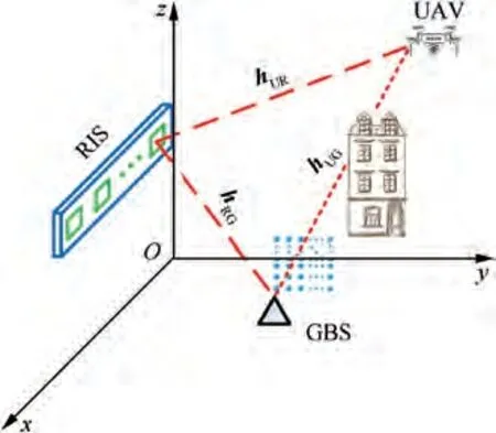
Fig. 1 RIS-based communication system.
From Fig.1,it can be found that the Uniform Planar Array(UPA) with the size of P×Q is equipped on the GBS, an omni-directional antenna is set on the UAV, and F reflecting elements called Uniform Linear Arrays (ULAs) are equipped on the RIS. Each reflecting element on the RIS can adjust the phase shift intelligently by a controller to construct a new communication channel among the GBS, the RIS and the UAV with the RIS being the medium. Note that there exists the low-power extensive scatters in obstructed channel,whose influence to the beam tracking can be omitted. In this sense, the obstructed communication channel hcan be abandoned,and a new connected communication channel consisting of hand his established via the RIS.
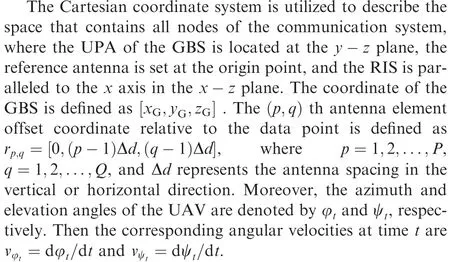
Next, a quasi-static mobility model is established for the UAV, where the velocity of the UAV is constant at each time duration of T, but may change as the time durations are altered. In the m th finite time span, m is divided into M time slots which means that m=0,1,...,M-1. In this case, the time duration is defined as MT. Each Tcan be discretized into K transmission blocks which are given by k=0,1,...,MK-1, and the length of the block is T=T/K. It is assumed that both the pilot symbols and the velocities of the UAV are unchanged since each transmission is short enough. The coordinate of the UAV is demonstrated as

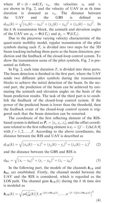
where h∈C, ρ is the path loss related to the reference distance D=1 m,λ is the carrier wavelength,d is the separation of antenna,and Φ(k )is the cosine of the arrival of angle for the signal from the UAV and the ULA at the RIS in the k th time slot.
Then, the channel between the GBS and the RIS is modeled, which can be regarded as an Rician fading model as follows:
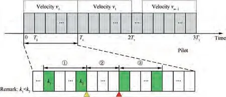
Fig. 2 Regular transmission of the pilot symbols.
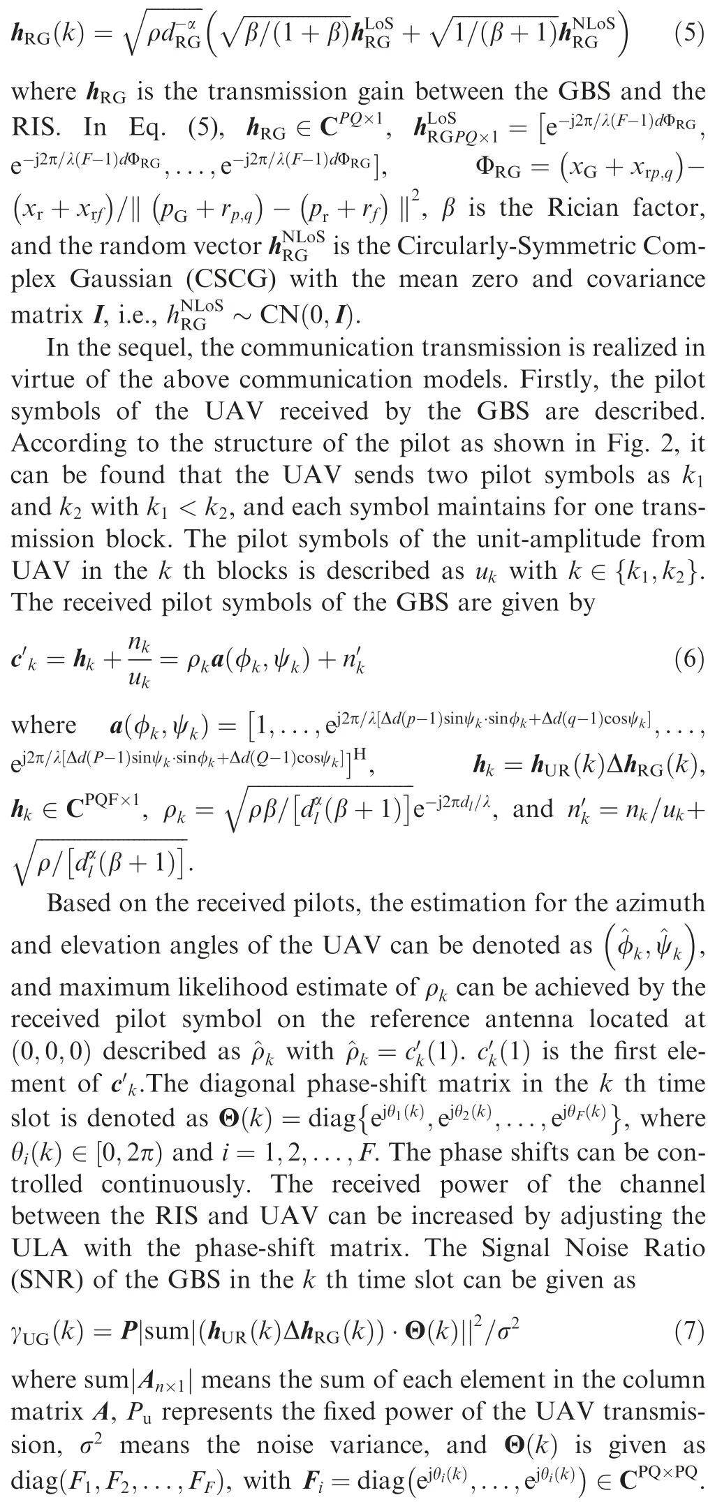
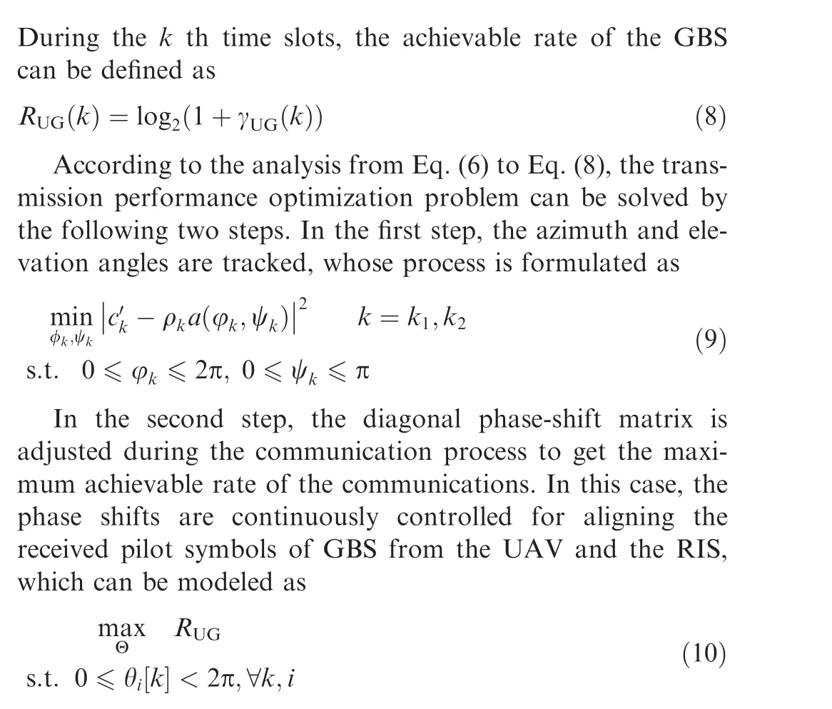
3. Algorithm for 3D beam tracking
In this section,the 3D beam tracking method is carried out for the RIS-based system, which can achieve the 3D beam tracking for the obstructed channels.To better understand the proposed method, the fundamental explanation of this beam tracking algorithm is described as follows.
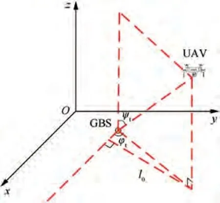
Fig. 3 Diagram of the angle relation.
3.1. Characteristics of UAV angular velocities
To describe the fundamental of the 3D beam tracking algorithm of the RIS-based system for the obstructed communications, it is significant to introduce the characteristics of UAV angular velocities.The 3D beam tracking can be achieved with the estimation of the relative angle information of the UAV,which can be iterative updated based on the beam tracking.
In this subsection, the characteristics of angular velocities are analyzed, which is the basis of explaining the principle of the algorithm. In this part, the variety are redefined, and the analysis process of v(t ) is described as follows. The diagram of the scene is shown in Fig. 3.
For one time duration like T,the UAV is flying straightly,and the velocity is
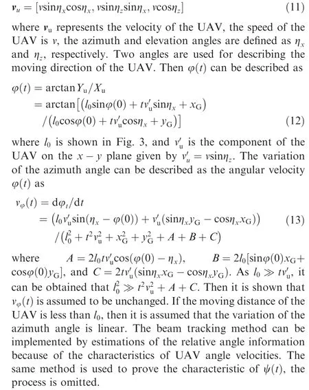
3.2. Overall algorithm
3.2.1. RIS-based 3D beam tracking algorithm
In this subsection, based on the above fundamental, the algorithm of 3D beam tracking for the RIS-based system is described as follows.
The core of realizing the 3D beam tracking is to get the estimation of the azimuth and the elevation angles of the UAV over time. In fact, the energy of the channel has an influence on the transmission of the pilot symbols to a certain degree. While the UAV is flying for a short distance,there existed the characteristics of angular velocities described above. The angular velocities for the UAV can be estimated with the received pilot symbols, then the azimuth and the elevation angles of the transmission blocks can be predicted. As the prediction of the angles is achieved,the phase-shift matrix between the RIS and the UAV can be calculated to optimize the channel transmission. Then an algorithm of the RIS-based 3D beam tracking method for obstructed communications is proposed, which can also enhance the transmission of the blocking channel between the UAV and the GBS. The algorithm steps are shown as the following Algorithm 1.
Algorithm 1. RIS-based 3D beam tracking algorithm.
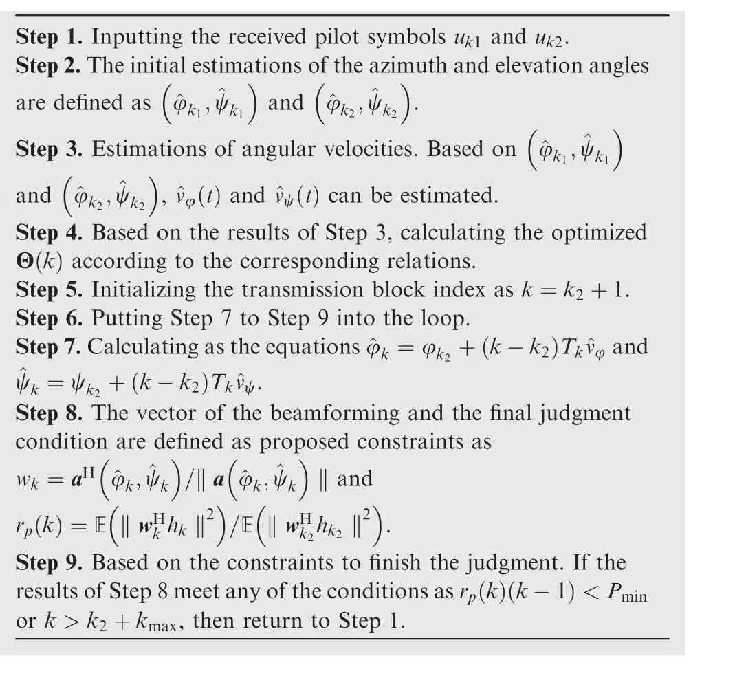
Step 1. Inputting the received pilot symbols uk1 and uk2.Step 2.The initial estimations of the azimuth and elevation angles are defined as ^φk1,^ψk1( )( )and ^φk2,^ψk2.( )Step 3. Estimations of angular velocities. Based on ^φk1,^ψk1( )and ^φk2,^ψk2, ^vφ (t ) and ^vψ (t ) can be estimated.Step 4. Based on the results of Step 3, calculating the optimized Θ(k ) according to the corresponding relations.Step 5. Initializing the transmission block index as k=k2+1.Step 6. Putting Step 7 to Step 9 into the loop.Step 7.Calculating as the equations ^φk =φk2 + k-k2( )Tk^vφ and^ψk =ψk2 + k-k2( )Tk^vψ.Step 8. The vector of the beamforming and the final judgment condition are defined as proposed constraints as wk =aH ^φk,^ψk( )( )/‖a ^φk,^ψk ‖ and rp (k )=E ‖wHk hk ‖2( )(/E ‖wHk2hk2 ‖2).Step 9. Based on the constraints to finish the judgment. If the results of Step 8 meet any of the conditions as rp (k )(k-1)<Pmin or k >k2+kmax, then return to Step 1.
3.2.2. Optimized algorithms for angles tracking
To solve the optimization problems as Eq.(9),which is related to Step 1 to Step 5 in Algorithm 1.The algorithm mentioned in this subsection is a tool to solve the optimization.According to the previous research, there are plenty of both traditional and intelligent algorithms used to address such an optimization problem. For the traditional algorithms, Violent Search Algorithm(VSA)is a simple and widely used algorithm, which can only solve simple optimization problems with low efficiency.For intelligent algorithms, Genetic Algorithm (GA)has a high usage rate, which can solve the optimization problems with complex principles in high efficiency but easy to achieve the local optimal solutions.
To search for a new method to solve the optimal solutions with high efficiency and high accuracy, new Mixed Genetic Algorithm(MGA)which combines VSA with GA is proposed.First, the improved algorithm can search the area where the optimal solution located in according to the initial solution information via VSA, and then solve the problem with GA in the located area.The global optimal solutions can be solved by optimizing iteratively in the located area. Note that the mixed algorithms used to solve such optimization problems can not only improve the efficiency of optimization process,but also get the accurate results. Furthermore, they can avoid both the drawbacks of the intelligent algorithms with falling into local optimum and the shortcomings of low efficiency for VSA.MGA is applied to search for optimal solutions with the following steps shown in Algorithm 2.
Algorithm 2. Mixed genetic algorithm.
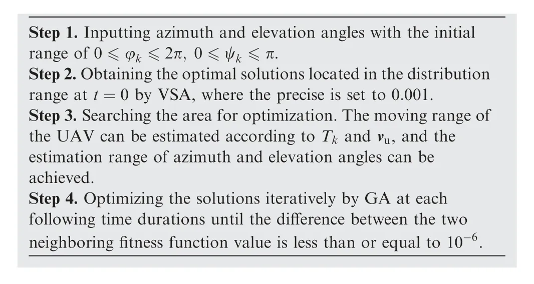
Step 1. Inputting azimuth and elevation angles with the initial range of 0 ≤φk ≤2π, 0 ≤ψk ≤π.Step 2.Obtaining the optimal solutions located in the distribution range at t=0 by VSA, where the precise is set to 0.001.Step 3.Searching the area for optimization.The moving range of the UAV can be estimated according to Tk and vu, and the estimation range of azimuth and elevation angles can be achieved.Step 4. Optimizing the solutions iteratively by GA at each following time durations until the difference between the two neighboring fitness function value is less than or equal to 10-6.
4. Simulation
4.1. 3D beam tracking results
4.1.1. Comparisons of optimization problem solving algorithms
The fishing boat was a scabby() old tub, but when you re only paying 15 dollars a person for three hours of fishing, you don t get the Queen Elizabeth II. There were several people on board, sitting on benches on each side of the deck. A few were in the cabin.
In this subsection, the algorithms are applied to optimize the accuracy of the angles tracking. The tracking results of UAV angles are the basic data used for realizing 3D beam tracking of the RIS-based system for obstructed communications.Hence, the accuracy of 3D beam tracking results can be influenced by the tracking results of the azimuth and elevation angles.The basic purpose of all algorithms is to achieve angles tracking, so it is significant for angles tracking in an accurate and efficient way.
(1) Comparisons between VSA and MGA
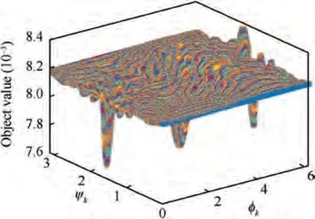
Fig. 4 Distribution range of the solution by VSA.
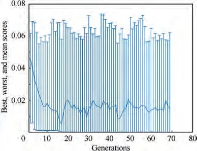
Fig. 5 Iterative optimization process of GA.
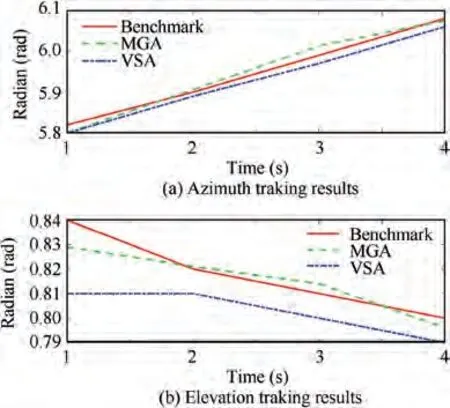
Fig. 6 Angles tracking results by MGA and VSA.
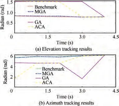
Fig. 7 Angles tracking results by intelligent algorithms.

Fig. 8 Detailed tracking results by MGA.
In this subsection, comparisons between VSA and MGA are taken as follows. Fig. 4 shows the distribution range of the solution at time 0 s via VSA, where both the distribution and the area range of the optimal solution can be roughly obtained. It can be calculated that the optimal solution is φ=4.208, ψ=0.848 at t=0 s by VSA. In this case,the result of Eq. (9) is 0.0076, and the moving range of the UAV related to T, and vcan be estimated as a circle at the radius of T·v, which can be used as the locked optimized range for the next time duration. Then optimizing solutions iteratively in the locked optimized range as well as the process for the iterative optimization in each duration time are shown in Fig.5,where the upper and lower bounds at each generation represent the maximum and minimum of the solutions,and the fitness function value at each generation formed a curve connected with the initial and the endless one.
The tracking results of azimuth and elevation angles are shown in Fig. 6, and it can be concluded that the VSA and MGA can achieve accurate tracking results for azimuth and elevation angles than by VSA. In the case of the different precise of GA and VSA, the tracking results should not be used for making comparisons. Note that the precise of GA is set to 0.001,while that of VSA is set to 0.01.Under the same conditions of hardware, the computing time of MGA is 6.341 s while that of VSA is 269.457 s.It is obvious that the efficiency of MGA is improved.
(2) Comparisons among intelligent algorithms
In this subsection, the comparisons among the proposed MGA,the single intelligent algorithms of GA,and Ant Colony Algorithm (ACA) are taken. The angles tracking results are shown in Fig. 7. For the tracking results of the elevation angles, the short dashed line represents the benchmark line,and the interleaved long and short dashed line, the solid line,and the long dashed line stands for the tracking results obtained by MGA,GA and ACA,respectively.For the tracking results of the azimuth angles, the green line stands for the benchmark line, while others are the same with the above.Firstly, the comparison between MGA and GA is taken. It can be concluded that the tracking results obtained by MGA are so close to the benchmark line that two lines are basically coincident. However, there exists large errors with the results taken by GA. According to the above analysis, MGA can achieve an accurate tracking result while GA cannot. Moreover, it can also be obtained from Fig. 7 that ACA cannot track the angles precisely. Both ACA and GA are easy to achieve the local solutions and are not stable for beam tracking. Hence, MGA is more effective than GA and ACA.
To demonstrate the accurate tracking results of MGA,more detailed results of angles tracking are shown in Fig. 8,which shows the performance for angles tracking. Therefore,accurate tracking results can be achieved by MGA, while the single intelligent algorithms cannot complete.Besides,the proposed MGA can avoid the shortcomings of the intelligent algorithms, which are easy to fall into the local optimal solutions.
Due to the flexibility of UAVs, it is required that the RIS can achieve the beam tracking in various scenes,which means that the RIS-based beam tracking method has wider practical applications. In the simulations, the following three scenes are taken into consideration.
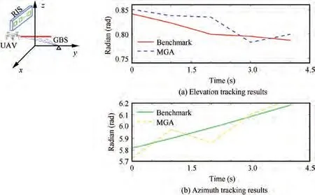
Fig. 9 Beam tracking results in straight line.
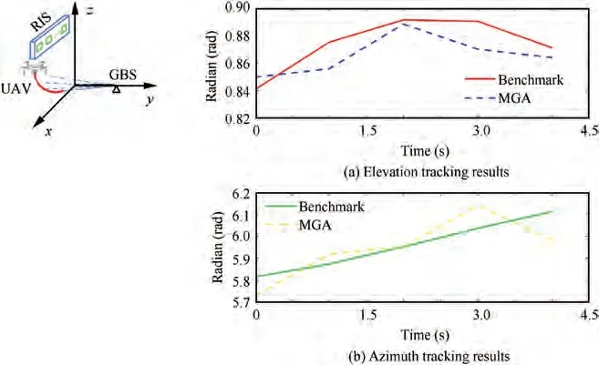
Fig. 10 Beam tracking results in circle.
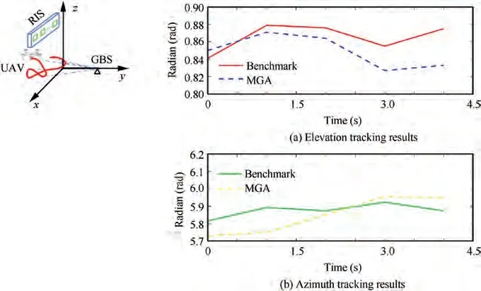
Fig. 11 Beam tracking results in random route.

Table 1 Phase-shift results.
Figs.9-11 stand for the 3D beam tracking for the UAV flying in a straight line,a circle and a random route,respectively.For the tracking results of the elevation angle,the dotted line is the beam tracking results for the obstructed channel using the RIS-based beam tracking method, while the solid line is the benchmark line. For the beam tracking results of the azimuth angle, the dotted line represents the results of the RIS-based beam tracking method, and the solid line is the benchmark.From the simulation results in Figs.9-11,it can be found that the results of the RIS-based beam tracking method have the same trend as the benchmark, and the tracking error is small,which means that the RIS-based beam tracking can be completed with an accurate result in the above three situations.In other words, although the channel between the GBS and the UAV is obstructed, the RIS-based beam tracking method can establish a new connected channel between the GBS and the UAV via the RIS, and can achieve the beam tracking.
4.2. Phase-shift results
In this subsection,the phase-shift results are shown in Table 1.To realize the coherent signals between the UAV and the RIS,the phase shift for each ULA is adjusted following the movement of the UAV as discussed in Step 4 of the proposed algorithm. In fact, the phase-shift adjustment is to realize better performance of the channel transmission. This simulation is also taken by MATLAB. Each row represents the phase shift of the ULA after the i th rotation, just as the Step 4 and Step 9 in Algorithm 1.When the results meet any conditions as Step 9,restart the calculation process.Because of the different position relations between the UAV and the RIS, the variation of each ULA is different.For each transmission block of the time duration,the phase shift will be different in order to maximize the received transmission power.
Table 1 shows the phase-shift results of each ULA are adjusting continuously. In fact, the coherent signals can be obtained by adjusting the phase shifts of the ULA. Because of the phase shifts,the RIS can play a positive role in achieving better performance of both communication transmission and 3D beam tracking of the RIS-based communication system for the obstructed channel. The RIS-based system achieve 3D beam tracking accurately in an optimized transmission.
5. Conclusions
This paper proposed an RIS-based 3D beam tracking method to solve the beam tracking problem with obstructed communications.A new RIS was constructed to realize the communications between the UAV and the GBS, and the effect of the transmission was improved by adjusting the phase shifts of the ULA on the RIS. According to the RIS-based system, a beam tracking method was proposed to track the UAV beams with obstructed communications. The RIS-based 3D beam tracking method can not only regulate the RIS to achieve the beam tracking of the obstructed communications,but also optimize the transmission efficiency of the channel. Finally, a new mixed algorithm with VSA and GA was taken to verify the feasibility of solving the optimization problems, and the simulations were carried out in different scenes for the RISbased 3D beam tracking.The future works will focus on studying the computational complexity of the proposed intelligent algorithm in this paper and searching for new methods for the beam tracking.
The authors declare that they have no known competing financial interests or personal relationships that could have appeared to influence the work reported in this paper.
This study was co-supported by the National Natural Science Foundation of China (Nos. 61867005 and 61703411).
 Chinese Journal of Aeronautics2022年8期
- Chinese Journal of Aeronautics的其它文章
- Active, compact, wideband, receiving filtenna with power adaptation for space-limited wireless platforms
- Deployment of SMP Miura-ori sheet and its application: Aerodynamic drag and RCS reduction
- An alternative method to reduce process-induced deformation of CFRP by introducing prestresses
- Novel orbit-attitude combination mode for solar power satellites to reduce mass and fuel
- Synthetic damage effect assessment through evidential reasoning approach and neural fuzzy inference: Application in ship target
- Experimental study on transfer functions of an active rotor under different flight conditions
