Experimental study on transfer functions of an active rotor under different flight conditions
Jinlong ZHOU, Linghua DONG, Weidong YANG
National Key Laboratory of Rotorcraft Aeromechanics, Nanjing University of Aeronautics and Astronautics, Nanjing 210016, China
KEYWORDS Active rotor;Helicopter;Trailing-edge flap;Transfer function;Vibration control;Wind tunnel test
Abstract Vibrations impose negative impacts on the effectiveness and public acceptance of helicopters. Active rotors with trailing-edge flaps have been proved to be an effective way to actively eliminate helicopter vibrations. For the existing control algorithm based on offline system identification,the transfer functions of an active rotor under different flight conditions are pre-requisites to implement closed-loop vibration control. In this study, a three-bladed active rotor with improved trailing-edge flaps is designed,and wind-tunnel tests are conducted to identify the transfer functions of this active rotor using frequency sweep and phase sweep methods. The experimental results demonstrate that these transfer functions are insensitive to the variation of flight speeds:the amplitude of the transfer function varies slightly, while the phase delay almost remains unchanged. In addition, this finding is validated through closed-loop vibration control tests with the active rotor.The transfer function obtained from the hover test results is also applicable to closed-loop vibration control tests under the forward flight conditions.This will dramatically simplify the implementation and operation of an active rotor.
1. Introduction
Vibration is one of the main problems faced by helicopters.Severe vibratory loads can not only degrade the comfort of crew members and passengers,but also cause serious problems such as structure fatigue.These vibrations are mainly from helicopter rotors.A helicopter rotor operating under forward flight condition will encounter a complex aerodynamic environment, including blade-vortex interaction, flow turbulence, compression for the advancing blade, and stall for the retreating blade.All of these make a rotor be the major source of vibrations for a helicopter. Therefore, it is of great value to implement vibration control techniques on helicopter rotors.
Vibration control techniques for helicopter rotors can be divided into passive vibration control and active vibration control. Some helicopters in service have been equipped with passive vibration control techniques, such as centrifugal pendulum absorbers and bifilar pendulum absorbers.However,these devices have limitations of large weight penalty and narrow working bandwidth. Due to the increasing requirements for helicopter vibration control, it is necessary to explore active vibration control techniques that can be implemented on helicopter rotors. An active rotor with Trailing-Edge Flaps (TEFs) is an effective method to actively suppress helicopter vibrations and noise.The dynamic flap deflection can affect the aerodynamic load distribution and the aeroelastic behavior of a helicopter rotor,and therefore it is capable of eliminating helicopter rotor vibrations.
Active rotors have received much attention over the last two decades, but previous studies have mainly focused on the design of actuation mechanisms or on the validation of vibration control authority, and most of them are aimed at vibrations at the blade passage frequency (it equals the rotor rotation frequency multiplied by the number of rotor blades,and rotor vibration at this frequency can propagate into fuselage through rotor hub). Numerical simulation of an active rotor was carried out by Friedmann using the comprehensive aeroelastic code AVINOR (Active Vibration and Noise Reduction).The simulation results showed that the vibratory hub loads at the blade passage frequency could be alleviated dramatically with the active deflection of the TEFs.
Experimental research is a powerful method because it can prevent neglect of some details in numerical simulation. Chopra et al. proposed different types of actuators, including the L-shaped actuator and the piezoelectric bender.Windtunnel tests were conducted to validate the performance of these actuators. Eric designed and tested an active rotor actuated by the X-Frame actuator.This active rotor was composed of an active blade with a TEF and a passive blade without a TEF.The X-Frame actuator was adopted by Boeing to actuate its full-scaled Smart Material Actuated Rotor Technology (SMART) rotor.Wind tunnel tests with the SMART rotor were carried out at NASA Ames Research Center. A 6 dB reduction in blade-vortex-interaction noise and an 80% reduction in hub loads were achieved. Two successful flight tests were accomplished by Airbus Helicopter using a BK-117 helicopter and an EC-145 helicopter respectively,and the maximum vibration reduction in forward flight conditions reached 80%.Collectively,these studies indicate that an active rotor with TEFs is a promising vibration control method for a helicopter.
In the aforementioned studies, the Continuous-Time Higher Harmonic Control (CTHHC) algorithm has been proved to be effective in closed-loop vibration control. The basic parameters of a CTHHC controller are determined by the transfer functions of an active rotor. Although there has been a considerable amount of identification methods for these transfer functions, few researchers have paid attention to the influence of flight speed on these transfer functions,since most of them focused more on the feasibility of vibration control using active rotors with TEFs or on the verification of TEF actuation mechanisms, rather than on further engineering application. Jacklin summarized five typical identification methods used for active rotors, including the weighted-leastsquare-error method, the Kalman filter method, etc.The least-square-error method was utilized in the flight tests conducted by Airbus Helicopter.Frequency sweep is another identification method that can be used for active rotors. Hall et al. identified transfer functions of the SMART rotor using the frequency sweep method, and closed-loop vibration control tests were carried out in two different flight conditions based on the corresponding identification results.Shin et al. conducted experimental research on another type of active rotor, namely the Active Twist Rotor (ATR).Wind tunnel tests of this ATR rotor demonstrated that the transfer functions of this ATR rotor only varied slightly with flight speed.It is reasonable to anticipate that a TEF rotor may also possess this characteristic;however,simulation of a TEF rotor performed by Frank reached an opposite conclusion.His study showed that the transfer functions of a TEF rotor were strongly dependent on flight speed. Therefore, wind-tunnel tests are necessary to evaluate the influence of flight speed on transfer functions of an active rotor with TEFs.
In this paper,experimental studies are carried out to assess the effect of flight speed on the transfer functions of an active helicopter rotor.A 2.4 m diameter,three-bladed active rotor is designed and tested on bench top. And then wind tunnel tests are conducted to identify the transfer functions of this active rotor at different flight speeds. Finally, closed-loop vibration control tests are performed based on the identification results to suppress the vertical vibrations of different frequencies.Wind-tunnel test results reveal that the transfer functions of this active rotor are insensitive to the variation of flight speeds.
2. Design and bench tests of active rotor with TEFs
2.1. Active rotor with TEFs
In order to evaluate the influence of flight speed experimentally, a three-bladed active rotor was designed based on a two-bladed active rotor, which has been successfully tested in an anechoic chamber to reduce in-plane noise.The new active rotor is presented in Fig. 1. The three main modifications are as follows:
Firstly, a new TEF consisting of an aluminum alloy frame and carbon fiber skins was designed as detailed in Fig.2. This composite structure reduced the mass of the TEF from 19.7 g to 12 g. The gap between a rotor blade and its TEF can decrease the aerodynamic performance of the TEF. In order to guarantee the profile of the TEF and reduce this gap, the aluminum alloy frame was manufactured using a highprecision CNC milling machine.
Secondly, flexible hinges were used to sustain the centrifugal loads of the TEF.These flexible hinges were made of composite materials, and they were characterized as high shear strength but low bending stiffness. On the other hand, the deformation of the flexible hinges resulted in not only TEF deflection, but also plunge motion that can decrease the effectiveness of the TEF. A pair of micro oil-free bearings was installed on the rotating shaft of the TEF to constrain its plunge motion. No additional lubrication was needed due to the flexible hinges and the oil-free bearings.
Finally, the number of blades increased from two to three.The dynamic and aerodynamic behavior of this three-bladed rotor with a hinge-less rotor hub is more similar to that of a real helicopter rotor compared with the original one with only two blades.And the test results obtained with this active rotor will provide more valuable guidance for the design and implementation of active rotors.
Table 1 lists the basic characteristics of this active rotor.
2.2. Bench tests of active rotor blades

Fig. 1 Active rotor with TEFs.
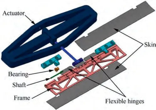
Fig. 2 Structure of TEF mechanism.
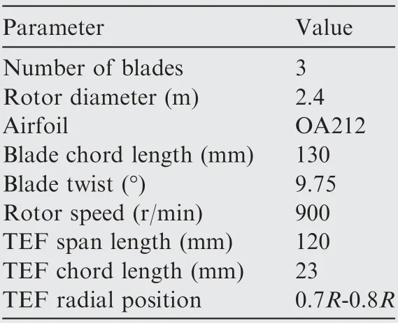
Table 1 Basic characteristics of active rotor and TEFs.
As shown in Fig. 3, bench tests were conducted with the TEF and its actuation mechanism to assess their performance. The bench tests mainly included two parts, namely the deflection angle calibration with steady-state control signals, and the transfer function identification with dynamic control signals.The deflection angle calibration tests were aimed to quantify the relationship between the control signals (before amplification) and the corresponding deflection angles of the TEF, and to explore its maximum deflection angle.The transfer function identification for the TEF and its actuation mechanism was used to assess their dynamic characteristics.
A ±4° deflection can be achieved under a non-rotating condition according to the test results (Fig. 4(a)).The transfer functions of the TEF system were also estimated in the non-rotating condition.Fig.4(b)indicates that resonance does not occur in the frequency range between 1 Hz and 90 Hz. It should be noted that the characteristics of the power amplifier was also included in these transfer functions, and as a result,the voltage in Fig.4 represented the weak voltage signal before amplification. The fundamental frequency of this active rotor was set to 15 Hz (900 r/min) in the wind-tunnel tests, and therefore, the TEF was capable of operating at frequencies up to 6 Ω (Ω is rotate speed) and even higher.
3. System identification methods and control algorithm
The block diagram of the closed-loop vibration control system is shown in Fig. 5. This system consists of the active rotor G(S), the power amplifier and the controller G(S).d(s) is vibratory loads to be reduced, y(s) is active rotor’s response to excitation signal of u(s), and z(s) is the measured vibratory loads. The power amplifier and the active rotor are integrated into the active rotor system with the transfer function G(s), and G(s) and is the system transfer function that will be identified in the following steps. In addition, the frequency response characteristics of the sensors and the corresponding signal conditioners are also integrated into G(s) for simplicity.
3.1. System identification methods
Offline identification methods are adopted for their advantages of high accuracy and reliability.The active rotor is treated as a Linear Time Invariant(LTI)system, and therefore,the relationship between the TEF control signal and the system response signal in steady state can be expressed as
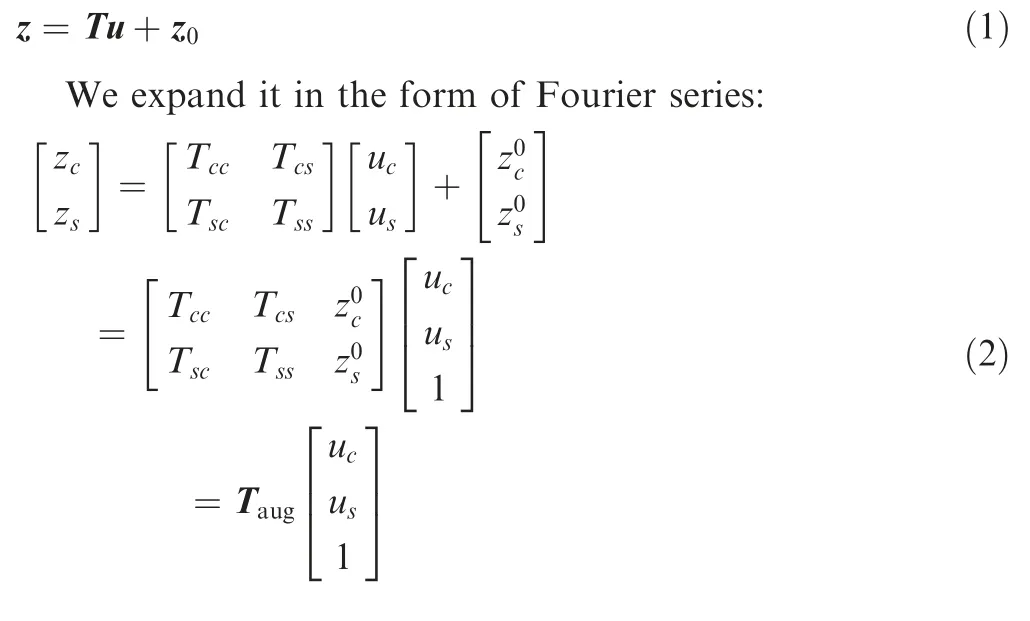
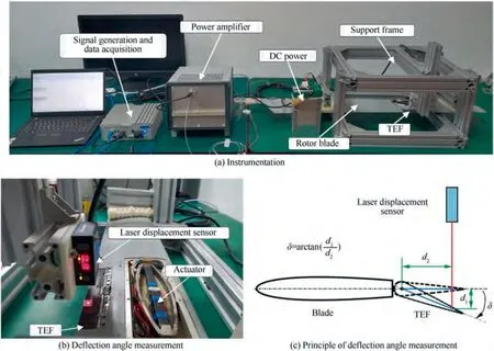
Fig. 3 Bench tests on TEF.

Fig. 4 Bench test results of TEF system.
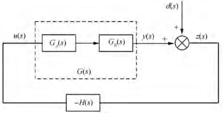
Fig. 5 Block diagram of active vibration control system.
where z is the system responses with TEF control input of u,zis the system responses with TEF control input of zero, Tand is the augmented transfer matrix. The identification error between the measured system response and predicted system response can be represented by
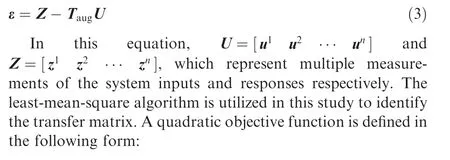
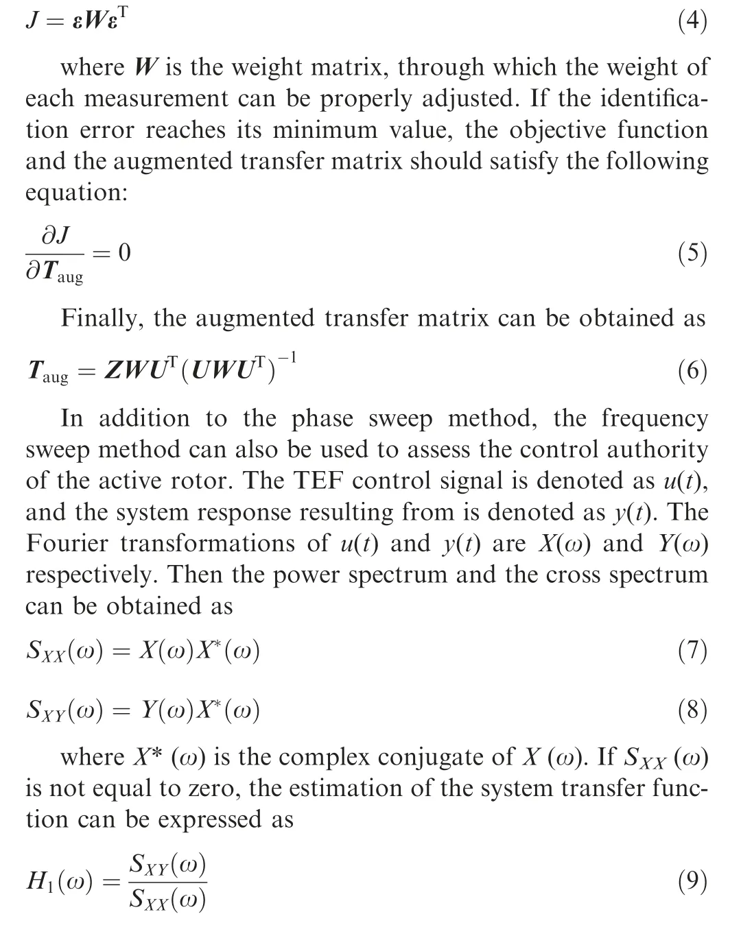
3.2. CTHHC algorithm
The effectiveness and reliability of the CTHHC algorithm for closed-loop vibration control have been validated through simulation and experiments.It works in time domain and no time/frequency transformation is needed. Therefore, it runs faster than the typical HHC controller and can respond more rapidly to the variations of helicopter vibrations.
The block diagram of CTHHC algorithm is presented in Fig. 6. Following modulation and integration, the acquired vibration signals are multiplied by the inverse of the transfer matrix. And then they are modulated again before they are added together to form the TEF control signals.All these procedures can be done in one period, which takes only 0.1 ms.Through Laplace transformation, the transfer function of the CTHHC controller is obtained as

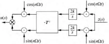
Fig. 6 Block diagram of CTHHC controller.
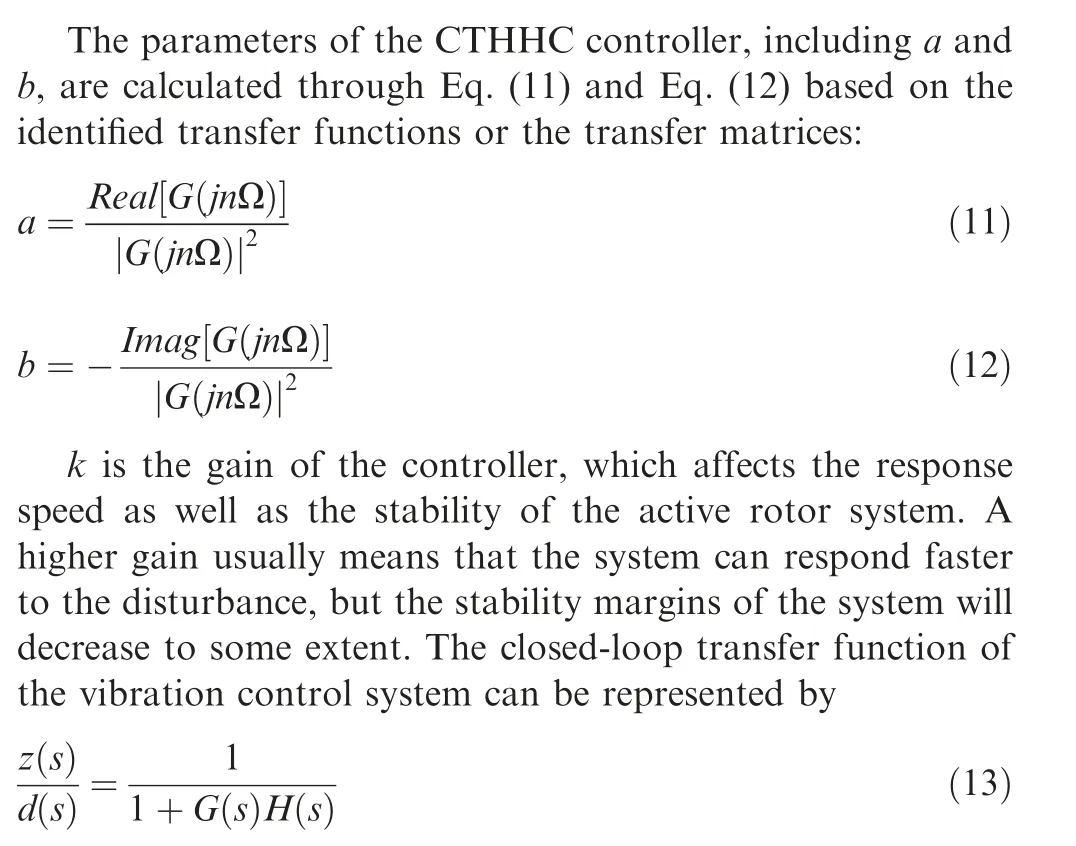
According to Eq.(13),s=jnΩ is the zero of the closed-loop vibration control system,and the loop gain at the frequency of nΩ is infinitely small. Therefore, the external disturbance will be rejected thoroughly.More details of the CTHHC algorithm can be found in Ref. 28.
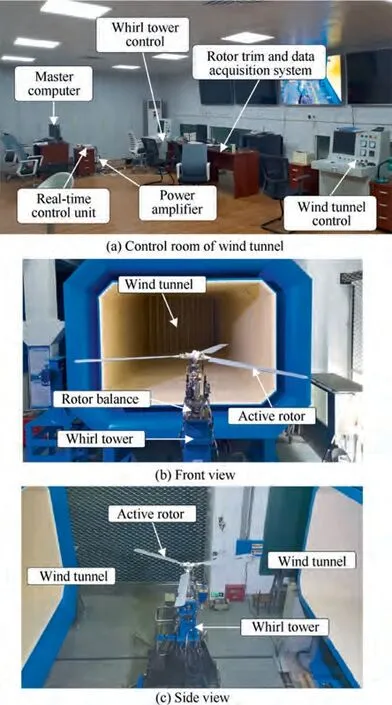
Fig. 7 Wind tunnel experiments.
4. Wind tunnel tests and discussion
4.1. Experimental states and experimental setup
Wind-tunnel tests were carried out in the open-jet tunnel of National Key Laboratory of Rotorcraft Aeromechanics in Nanjing University of Aeronautics and Astronautics. As shown in Fig. 7, the active rotor is put in the test section with a width of 3.4 m and a height of 2.4 m.This test section is capable for a scaled rotor with a maximum diameter of 2.5 m.Both hover and forward flight tests can be conducted in this test section. System identification using two different methods and closed-loop vibration control were performed at different flight speeds and harmonics. Detailed experimental states at advance ratio (a non-dimensional speed and it is defined as the ratio of forward flight speed to the rotor tip speed) of μ=0.053 are listed in Table 2 as an example.These experimental states were repeated for different flight speeds with the same rotor thrust of 17.5 kg. And the rotor was trimmed to confine its maximum mean pitching and rolling moments within 3 N·m.

Table 2 Experimental states for forward flight at advance ratio of μ = 0.053.
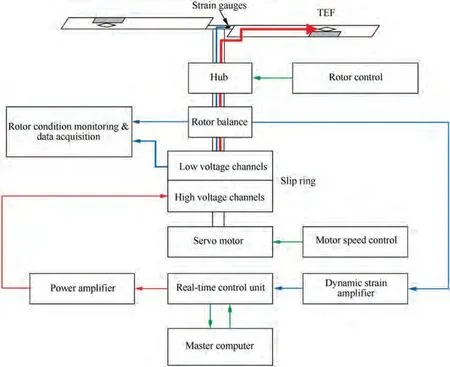
Fig. 8 Schematic diagram of equipment used in closed-loop vibration control experiments.
Fig. 8 shows the schematic diagram of the equipment used in the wind-tunnel tests.The active rotor was driven by a servo motor. Its rotational speed was set to 900 r/min with a fluctuation of about±1 r/min.A slip ring,which was used to transfer signals from the fixed frame to the rotating frame or vice versa,was mounted on the rotor shaft.A five-component rotor balance was installed under the rotor hub, which was used to measure the hub forces and moments of the active rotor. In this study, vertical force was selected as the system response in the system identification and closed-loop vibration control.Considering the safety of the whirl tower and the active rotor,accelerometers were attached on the whirl tower and accelerations at different directions were monitored.
For system identification, chirp signals or sinusoid signals were generated by a real-time control unit. The basic parameters of control signals were set through a master computer that was connected to the control unit via Ethernet. After being amplified by the power amplifiers, TEF control signals were transferred to the TEF actuators through the high voltage channels of the slip ring. Then the TEFs deflected according to the accepted control signals and the active rotor generated responses including forces and moments. These vertical force responses were measured by the rotor balance. Both the TEF control signals and the response signals were logged by the real-time control unit.
This system was also used to conduct closed-loop vibration control tests. The CTHHC algorithm was implemented in the real-time control unit. TEF control signals were calculated based on the vibration signals measured by the rotor balance.In this work, vertical forces were selected as the feedback signals. In addition, strain gauges were attached on the blade roots to monitor the root loads for safety.
4.2. Frequency sweep test results and discussion
Frequency sweep tests were conducted in different flight conditions, including hover and forward flights at advance ratios from μ = 0.053 to μ = 0.11. The TEFs were excited by chirp signals as demonstrated in Fig. 9(a). The frequency range of these chirps was from 1 Hz to 65 Hz; hence harmonics of the rotation frequency from 1 Ω to 4 Ω were covered. From Fig. 9(b), we can see that there is an obvious peak in the vertical force responses. This peak implied that one of resonant modes of this active rotor was excited by the TEFs.
Transfer functions of this active rotor at different flight speeds are shown in Fig.10.These transfer functions indicated:
Firstly, there was a resonant frequency at about 18 Hz for this active rotor. According to the bench tests on the active rotor blade, the resonance frequency of the actuation mechanism was higher than 90 Hz. Therefore, this resonant frequency did not result from the actuation mechanism. It was recognized as the first flap bending mode for this active rotor.
Secondly,the variations of the transfer function at different flight speeds were not significant.The amplitude varied slightly with the increase of the flight speed, while the phase delay almost remained unchanged.The minor variation in the amplitude is due to the increase of flow speed in forward flight conditions, which enlarges the aerodynamic loads of the TEFs.These findings were in agreement with Shin’s experimental results of an active twist rotor.
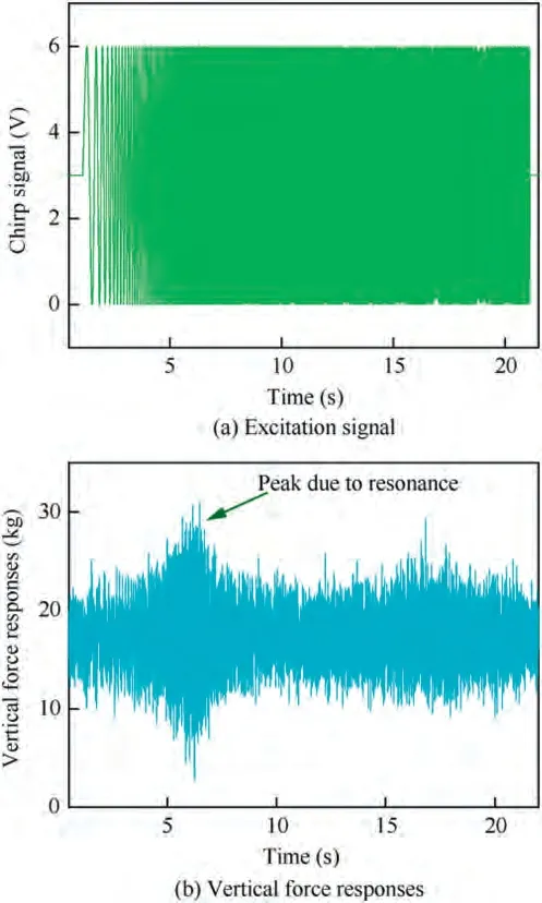
Fig.9 Time-domain signals of frequency sweep tests at advance ratio of μ = 0.053 .
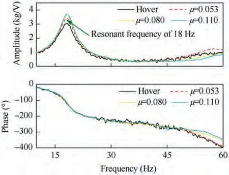
Fig. 10 Transfer functions of active rotor system at different flight speeds.
Finally, the vibration control authority of this active rotor was dominated by the servo-flap effect instead of the direct effect. For an active rotor with TEFs, there are two ways to change the aerodynamic loads of the rotor.The first one is called the direct effect, which means that TEF deflection changes the lift coefficient of the airfoil directly. The second one is called the servo-flap effect. TEF deflection results in pitch moment, which makes a flexible rotor blade twist and bend. And then the flexible deformation changes the aerodynamic loads of the rotor. The direct effect usually occurs for a rigid rotor blade,while the servo-flap effect will play a dominant role for a flexible rotor blade.And usually the servo-flap effect consumes less energy to achieve the same vibration control performance compared with the direct effect.
4.3. Phase sweep test results and discussion
Phase sweep tests were conducted to obtain the transfer matrices at individual frequencies of 1 Ω,2 Ω,3 Ω and 4 Ω.The TEF control signal for 1 Ω test with initial phase of 60°is shown in Fig. 11(a) as an example.
It can be seen from Fig.11(b)that the active rotor generates obvious responses to TEF control signals, and similar trend was also seen in tests at other flight speeds.
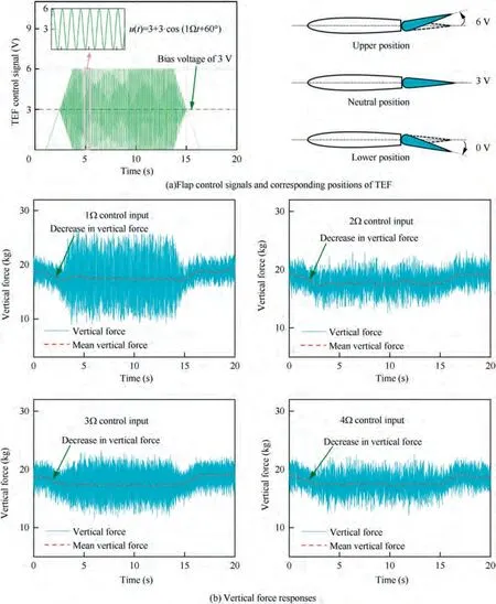
Fig. 11 Flap control signal and vertical force responses of phase sweep tests for flight speed of μ = 0.053 .
As can be seen from Fig. 9(b) and Fig. 11(b), the dynamic deflection of the TEFs did not significantly change the mean vertical forces; hence it did not influence the primary control of this active rotor. On the other hand, dramatic decrease appeared when the TEF control voltage raised from 0 V to a bias voltage of 3 V. This decrease results from the upward deflection of the TEFs. In order to achieve a balanced output,bias voltages should be applied to the piezoelectric actuators of the TEFs as shown in Fig. 11(a). When the control signal increases from 0 V to the bias voltage, the TEFs deflect upward from their initial position to the neutral position.This upward deflection decreases the lift coefficient of the airfoil,and consequently reduces the vertical force of the rotor.These variations in the vertical forces have further strengthened our confidence in the vibration control authority of this active rotor.It should also be noticed that the amplitudes of the vertical force responses for 1 Ω TEF control input were much higher than others.This is due to the fact that 1 Ω is much closer to the modal frequency of the first flap bending mode for this active rotor.
The elements of transfer matrices represent the system frequency responses at specific frequencies. The results of the phase sweep tests are shown in Fig.12 in the form of real part and imaginary part.
The central point of each hexagon in Fig.12 represents the rotor vibrations without TEF control input. The rotor vibration characteristics including phase and amplitude changed with the variation of flight speed especially for the 3 Ω vibrations,while the area of each hexagon,which reflected the control authority of the active rotor, changed less dramatically.And this is in agreement with the results of frequency sweep.
Interestingly, for tests of 1 Ω, 2 Ω and 4 Ω TEF control inputs, the origin of the coordinates was surrounded by the hexagons. This implied that vibrations at these frequencies were within the control authority of the active rotor, and they could be cancelled thoroughly under ideal conditions.Although the origin of the coordinates located outside of hexagons for 3 Ω vibrations in forward flight,there were still points on these hexagons that were much closer to the origin than the central points, which means that acceptable vibration reductions can still be achieved for these vibrations
4.4. Comparison of identification results between frequency sweep tests and phase sweep tests
The system characteristics of this active rotor were obtained in both the frequency sweep tests and the phase sweep tests. The results from these two identification methods are presented in Fig.13.And comparisons are made to validate the accuracy of the identification results.
As shown in Fig. 13,the identification results from the frequency sweep tests are in good agreement with those from the phase sweep tests.It should also be noted that flight speeds still had slight influence on the system frequency responses,and both of these two identification methods captured this phenomenon.To sum up,these comparison results offer compelling evidence for the accuracy of the system identification results.
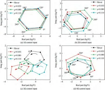
Fig. 12 System frequency responses from phase sweep tests.
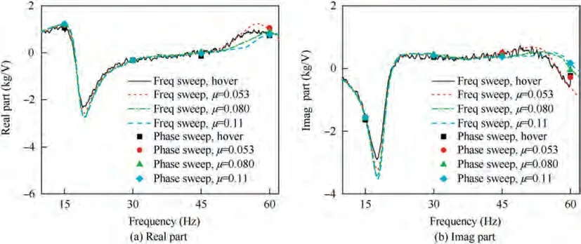
Fig. 13 Identification results from frequency sweep tests and phase sweep tests.
4.5. Closed-loop vibration control based on identification results of different flight speeds
After the system identification at different flight speeds,closedloop vibration control was performed in the wind tunnel. For the vibration control tests at each flight speed, the controller parameters were determined by the identification results obtained at the same flight speed. Fig. 14 shows the vibration reductions for the 3 Ω vertical force.
As soon as the controller was turned on, the 3 Ω vertical force decreased rapidly.As anticipated in the system identification tests, the 3 Ω vertical force was almost completely cancelled in hover condition, while only part of it was eliminated in forward flight. Even though the vibration control authority of this active rotor was not high enough to completely eliminate the 3 Ω vibrations,the active rotor as well as the CTHHC controllers still showed acceptable vibration control performance for the blade passage-frequency vibrations.
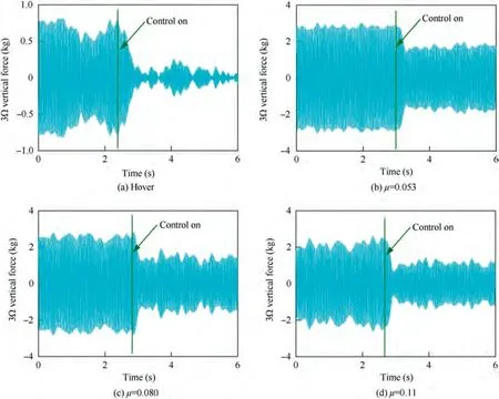
Fig. 14 Vibration reductions for 3 Ω vertical force at different flight speeds.
In order to expand the application of this active rotor,closed-loop vibration tests were also carried out for rotor vibrations at other frequencies, including 1 Ω, 2 Ω and 4 Ω.Vibration reductions for these harmonics at different flight speeds are shown in the Fig. 15.
Remarkably,rotor vibrations at these frequencies were suppressed dramatically at different flight speeds.The active rotor can be repurposed to eliminate vibrations of different frequencies without any modification of its hardware. This is an important advantage of an active rotor over traditional passive vibration control techniques.
Frequency-domain analyses were performed to assess the side effects of TEF inputs.If the active rotor alleviated the vibration at a specific frequency but enlarged vibrations at other frequencies simultaneously, it would not be an entirely practical method for rotor vibration control. Vibration control results in frequency domain are presented in Fig.16,and no significant side effect was found for this active rotor.The vibration at the target frequency was reduced dramatically,while vibrations at other frequencies remained nearly unchanged. Test results of flight speed at μ=0.053 are listed in Fig.16,and similar phenomena also appeared in the test results of other flight speeds.
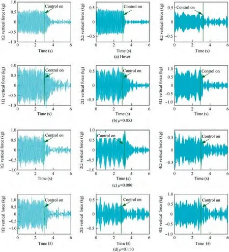
Fig. 15 Vibration reductions of non-passage-frequency vibrations at different flight speeds.
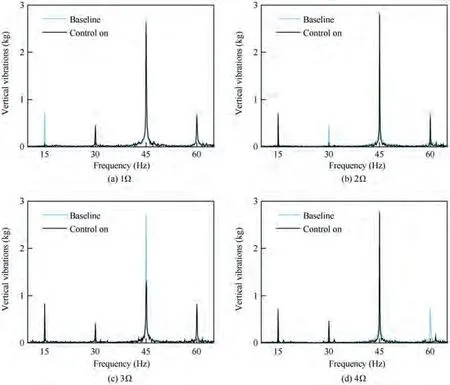
Fig. 16 Vibration reductions at flight speed of μ = 0.053.
4.6. Closed-loop vibration control tests based on identification results of hover
Given the fact that the transfer functions of this active rotor did not change dramatically at different flight speeds, closedloop vibration control tests were also conducted at these flight speeds based on the identification results obtained in hover.
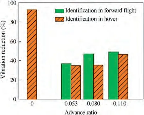
Fig.17 3 Ω vibration reductions based on different identification results.
Fig. 17 indicates that significant vibration reduction can still be achieved in this way. For tests with controller parameters determined by the identification results of forward flight,the 3 Ω vibration reductions reached 36.5%, 46.9% and 48.8% for flight speeds of μ = 0.053, μ = 0.080 and μ =0.11 respectively. For tests with controller parameters determined by the identification results of hover, the vibration reductions were 34.8%, 35.2% and 46.3% respectively.Although there was some degradation in the vibration reductions, it was still acceptable to carry out closed-loop vibration control tests in this way on account of the fact that the system identification was dramatically simplified.
5. Conclusions
Transfer functions of an active rotor are important for closedloop vibration control. An active rotor with TEFs was designed and tested in a wind tunnel. Its transfer functions were identified under different flight conditions. The effect of flight speed on the transfer functions was investigated experimentally. Appealing vibration control performance was achieved based on the identified transfer functions. The conclusions are as follows:
(1) The TEF mechanism designed in this study was effective to suppressive rotor vibrations. A 92% reduction in the 3 Ω vertical vibration was achieved in hover, and the maximum reduction in forward flight conditions was 48.8%which was achieved at advance ratio of μ=0.11.Significant vibration reductions were also achieved for the vertical vibrations at other frequencies.These results validate the feasibility and effectiveness of the proposed TEF mechanism,revealing that it has the potential to be used for the active rotor of a real helicopter.
(2) Flight speeds only imposed limited influence on the transfer functions of this active rotor. The amplitude of the transfer function varied slightly with the increase of the flight speed, while the phase delay almost remained unchanged. Consequently,it might be feasible to conduct system identification only for several typical flight speeds instead of for all flight speeds within the whole flight envelope.This finding can significantly simplify the engineering application of an active rotor with TEFs, which makes this type of active rotor more practical.
(3) Closed-loop vibration control could be conducted at different flight speeds based on the identification results obtained in hover. Even though some degradation appeared in the vibration reductions, it was still acceptable since the system identification was dramatically simplified.
The wind-tunnel tests in this paper were limited by the performance of the wind tunnel, and thus the maximum flight speed was μ = 0.11. Future work will focus on wind-tunnel tests at higher flight speeds to validate the above conclusions in a wider range of flight speeds.
The authors declare that they have no known competing financial interests or personal relationships that could have appeared to influence the work reported in this paper.
This study was co-supported by the National Natural Science Foundation of China (No.11402110) and a project funded by the Priority Academic Program Development (PAPD) of Jiangsu Higher Education Institutions, China.
