Path,feedrate and trajectory planning for free-form surface machining: A state-of-the-art review
Yuwen SUN, Jinjie JIA, Jinting XU, Mnsen CHEN, Jinbo NIU
a School of Mechanical Engineering, Dalian University of Technology, Dalian 116024, China
b School of Automotive Engineering, Dalian University of Technology, Dalian 116024, China
KEYWORDS CNC machining;Feedrate;Free-form surface;Robotic machining;Tool path;Trajectory
Abstract Nowadays, free-form surfaces have been widely used in various industrial fields. They are usually machined by CNC machine tools, but recently have also begun to be manufactured by industrial robotic arm manipulators,thanks to low cost,large operation reaching space and high machining flexibility of robot. So far, various methodologies have been proposed to improve efficiency and quality of free-form surface machining, thus this paper aims at providing a state-ofthe-art review on research advances in free-form surface machining. In this review, tool path generation,feedrate scheduling in Cartesian space and trajectory planning in joint space are focused for both CNC machining and robot machining,and their research statues, existing difficulties and key issues are discussed in detail. Finally, the feasible routes, breakthrough points and future development trend are also expounded.
1. Introduction
Free-form surfaces, also called sculptured surfaces, have been widely used in industrial fields ranging from aerospace, automotive, ship building, and the die/mould to consumer products. It is often used to describe parts with complex shapes and aesthetic or functional requirements, e.g. aircraft skins,blades, impellers and propellers.In the past decades, significant research and efforts have been done for design and manufacturing of parts with free-form surfaces. Almost all CAD/CAM systems have the ability of designing free-form surfaces and planning the machining processes of free-form surfaces.In general, free-form surfaces are machined by 3/5-axis CNC machine tools, but recently have also started to be manufactured using industrial robots,typically,robotic arm manipulators, thanks to low cost, large operation reaching space and high machining flexibility of robot.Although their mechanical configurations and kinematics structures are different, as shown in Fig. 1, the attempt to draw a sharp line to differentiate machine tools and machining robots from the perspective of machining is not straightforward in general sense, and depends on the specific scientific and technical discipline.In robotic scientific discipline, 3/5-axis CNC machine tools are classified as Cartesian robots, however machining robots,referring to robotic arm manipulators in this paper,can be also considered to be CNC machines that install different end effectors for specific machining tasks, e.g. polishing and milling.
In traditional sense, the term ‘‘machining” is considered to be such technologies closely related to machine tools, while machining robots can also accomplish multiple machining tasks after integrating specific end effectors that can present similar capabilities as cutters mounted on machine tools. By means of various end tools, both robots and machine tools can machine a part with free-form surfaces from a blank along the planned tool paths, and motions of translational axes and rotary axes for machine tools,and joints for robots can be controlled by a CNC unit. Both for machining robots and CNC machine tools, the machining efficiency and quality of freefrom surfaces depend on planned tool paths,feedrate in Cartesian space and trajectory in joint space to a large extent.The three issues are closely related and coupled with each other for free-form surface machining,but in the view of the difficulty of solving the problem that considers tool path,feedrate and trajectory planning at the same time,many researches and efforts have been made to solve them separately.At present,there are many literature reports about automatic tool path generation methods and feedrate strategies for 3/5-axis CNC machine tools,while robot machining focuses mainly on joint trajectory planning. Considering the similarity between CNC machining and robot machining, the developed tool path generation methods for CNC machining of free-form surfaces can be applied to robot machining with slight modifications. Nevertheless,feedrate scheduling for CNC machining and trajectory planning in robotic filed are quite different,due to their inherent different kinematic and dynamic properties, as well as the encountered issues in practice. Therefore, this state-of-the-art review focuses on these three most important issues.
For tool path generation, Lasemi et al.and Makhanovprovided reviews covering the literature before 2010. Therefore, this review will focus on more recent developments of tool path generation methods, as well as feedrate and trajectory planning strategies. The existing problems, development trends and research directions are also discussed in detail.The rest of this paper is organized as follows. Tool path generation,which focuses on cuter contact(CC)path construction and tool orientation optimization, are discussed in Section 2.Section 3 introduces feedrate scheduling strategies in detail,followed by joint trajectory planning for robot machining discussed in Section 4. Finally, the conclusions are presented in Section 5.
2. Tool path generation for free-form surface machining
The machining process is driven directly by tool path planned on free-form surface for CNC machine tools and robots, thus generating tool path in an efficient manner becomes very critical.Generally,tool path planning is composed of two aspects:CC path topology construction and tool orientation determination. The former, CC path topology, is defined by the pattern that the cutters or effectors move to mill the surface,and the latter, tool orientation, is represented by tilt angle α and yaw angle β to avoid the local gouging and global collision appearing possibly in machining. Many researches and efforts have been carried out on tool path generation in these two aspects. So, in this section, the advances in CC path construction and tool orientation determination are first reviewed in detail.
2.1. Traditional CC path construction and improvement
CC path construction can be described as a process of reasonably arranging a family of curves that can effectively cover and approximate the free-form surface to be machined under the constraint of allowable scallop height. Therefore, CC path construction can be divided into the following two sub-steps:the selection of curve family on surface, and the design of effective and reasonable path arrangement manner. For the former, iso-parameter curves, iso-scallop curves, iso-planar curves and geodesic curves, etc., can be all selected as the choice of curves to cover the free-form surface. The available manners for the second sub-step to effectively arrange the selected curves include Zig-zag pattern, contour-parallel pattern and spiral pattern, and so on. Naturally, CC path can be generated via different combination of curve family and path arrangement pattern, depending on the complexity of path computation and the requirements of machining manner and efficiency and quality of free-form surface machining.The commonly used CC paths include: iso-parameter path,which is easy to be calculated,iso-scallop path,which maintains constant scallop height between adjacent paths across the whole surface, and iso-planar paththat is suitable for all types of surfaces, e.g. parametric surfaces, point cloud and mesh models.
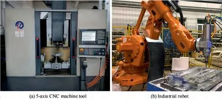
Fig. 1 5-axis CNC machine tool and industrial robot used widely for free-form surface machining in industrial applications.
In order to improve the machining efficiency and quality of free-form surfaces,many efforts have been accomplished in an attempt to enhance the applicability of the traditional methods.For example, boundary-conformed iso-parameter path planning methodsand parameter-based spiral path methodswere proposed successively by means of reparameterization of trimmed surfaces for high-efficiency machining of trimmed free-form surfaces with complex shape. When the iso-scallop path method was adopted for machining freeform surface, a shorter overall path length could be achieved by elaborately selecting the optimal initial CC path instead of directly using the boundary curve.Taking the curvature changes of a surface, machining strategies and requirement of surface roughness into consideration, Quinsat and Sabourinimproved the iso-planar method in terms of the reduction of machining time via optimal selection of sectional plane normal. Introducing the harmonic mapping into the field of free-form surface machining, Sun et al.proposed a dimension-reduced methodology of planning CC path, as shown in Fig.2.This mapping-based methodology can reduce the task of planning CC path on a 3D surface to designing guide curve on a planar domain, and is also suitable for all types of surfaces. On the basis of their previous work,Sun’s team have developed successively high-speed spiral path planning methodsperformed respectively on genus-0 and nonzero genus surfaces, a boundary-conformed machining methodfor trimmed free-form surface with multiple patches.In addition, a unified self-intersection elimination criterion based on the local loop, which aims to effectively handle the issue of uniform or non-uniform offsets of open and closed paths, was proposed in their work.Moreover, they developed contour-parallel tool path generation methods suitable for free-form surfaces with holes and other non-machining regions.These above-mentioned tool path generation methods are computationally simple and robust,and will continue to dominate in tool path generation for free-form surface machining.Strictly speaking,these methods generate tool path from the geometric point of view,which focus only on the geometric feasibility of machining along the planned tool path.However, the influence of the configuration of machine tool,cutting directions and dynamic characteristics in machining process on the tool path has not been sufficiently investigated.
2.2. Recent vector field based CC path generation method
Since Chiou and Leeintroduced the concept of vector field to plan CC path with maximum cutting strip width on free-form surfaces, the tool path generation methods have evolved from traditional geometric path planning to the methods, in which the CC paths are generated by considering not only the geometric characteristics of the surface to be machined, but also the smoothness and continuity of tool motion, dynamic characteristics of the machine tool,and even the physical properties and performance requirement of the surface.Vector field is a powerful mathematical tool that can integrate effectively the geometric and physical characteristics in free-form surface machining, thus vector field based tool path generation methods have been becoming the focus of research and future development trends in the field of tool path planning. In the implementation of such method, the part surface is first discretized uniformly into a grid of points, and then at every point, the optimal cutting directions are determined, in order to realize different optimization objectives. The preferred cutting direction at CC point has a variety of options,which may be the one that maximizes the cutting strip width,the federate,the material removal rateand the kinematics performance,or minimizes the cutting force and deformation,and the consumed energy in the machining process,or is based on construction of the fluid streamlines on the surface,or even is the one that is specified according to the machining intent or expected machining performance of the designers at every CC point. Undoubtedly, vector field,serving as a combined description tool for both geometric and physical characteristics in free-form surface machining,can bring the great flexibility for tool path planning. Fig. 3 shows a vector field constructed in parametric domain for maximum cutting strip width. From Fig. 3, it is seen that vector field can describe the optimal cutting direction at arbitrary CC point on the surface. The key issue that remains to be settled in vector field based method lies in how to generate the tool paths that can visit every sampled point and follow smoothly the cutting direction at every point, such that the optimal cutting directions at every sampled point are respected to the largest extent, after the vector field is successfully constructed.
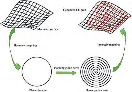
Fig. 2 Dimension-reduced methodology of planning tool path proposed by Sun et al.21
To solve this challenging issue of generating CC path from vector field, Moodleah and Makhanov,and Manav et al.adopted the heuristic searching strategy to force the cutter to visit each CC point and obey the preferred cutting directions at every CC point, in an attempt to guarantee that the CC path, which owns the best matched cutting directions with the established preferred ones, can be generated. However,the connection among the discrete points will inevitably cause frequent tool entry and exit, and even the sudden turns and sharp corners in path, which may decrease the machining efficiency and surface finish. In the method proposed by Chiou and Lee,a vector field that consists of a collection of cutting directions with maximum cutting strip width is first constructed on the surface, and subsequently according to the principle of the largest average cutting strip width, an optimal initial tool path is identified, which is then propagated inside the whole surface by offsetting method, thereby generating tool path with maximum cutting strip width. Furthermore,Kumazawa et al.and Liu et al.proposed the rank-two tensor based CC path generation methods. In their methods,the surface was first subdivided into sub-surfaces by means of identifying three types of degenerate points of the tensor field,as shown in Fig.4,and then on each sub-surface,an initial tool path was determined according to the principle of the largest average cutting strip width or using the middle pathline of that region,finally the rest paths were generated via the traditional iso-scallop method by propagating the initial path along the sub-surfaces.
However, limited to the offsetting operation, once the initial tool path was determined, the distribution of the whole path, which is generated by offsetting the initial path across the surface, and the feed directions at CC points are largely determined.Despite that the cutting directions along the initial path own the minimum deviations from their preferred directions, other paths, which are generated from the initial path,might deviate gradually from the preferred cutting directions at CC points, due to the anisotropic preferred cutting directions at every CC point on the surface.To overcome the inherit shortcoming brought by the methods above,Sun et al.introduced the concept of streamline field to describe the cutting directions at sampled points.In their methods,the cutting directions on the surface were mapped into the corresponding parameter domain using the following equation:

where (δu,δv)represents the cutting direction in the parameter domain,τ stands for the magnitude of cutting direction on the surface and is usually 1, E is the first fundamental matrix of surface, whose element is e, and θ is the angle between the cutting direction and r, where ris the first partial derivation of the surface r(u,v ) with respect to u. Subsequently, the cutting directions in the parameter domain are supposed to be the flow directions of an incompressible plane flow, then stream function can be adopted to capture the cutting directions at arbitrary points and the level curves of the stream function, i.e. streamlines, can be used as the potential guide paths in the parameter domain.The generated CC path using the streamline field based method has the salient characteristics of being tangential to the cutting directions at every CC point,having no sharp corners and neither self-intersecting nor intersecting with each other. Furthermore, the condition that how the corresponding vector fields on the compound surface maintain G1 continuity was also fully discussed in their method,providing the ability for this method to ensure the smooth transition of streamline-like path across the boundary of the adjacent patches.Fig. 5 shows the planned CC path by the streamline field based method on a compound surface with two patches. It is observed clearly that smooth, continuous path is generated over the multiple vector fields on all patches of a compound surface.
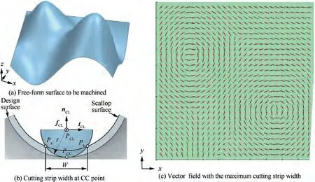
Fig. 3 Vector field with maximum cutting strip width for free-form surface machining using ball-end cutter.35
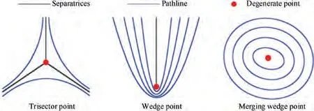
Fig. 4 Types of degenerate points in tensor field.36
2.3. Traditional local adjustment methods for tool orientation
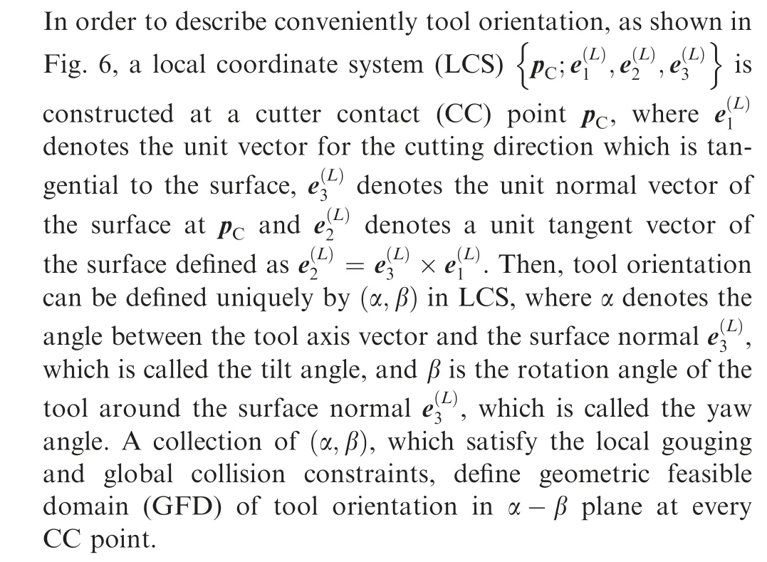
Initially, the research of tool orientation determination has focused mainly on finding the optimal tool orientation for the purpose that the local gouging and the global collision can be successfully avoided.To achieve that goal, the curvature matching method,which aims to detect and eliminate the local gouging at a CC point, is proposed. In addition, multipoint tool positioning strategy,arc-intersect algorithm,rolling ball methodand triangular mesh offset approachare demonstrated to be effective in the processes of local gouging detection and elimination. To generate collision-free tool orientation, the C-space method,visibility cones based algorithmand a physically-based potential field approachare proposed for 5-axis machining. Further, Chiou and Lee,Fard et al.and Bedi et al.proposed to optimize the tool orientation of a flat-end or toroidal cutter at a CC point in an attempt to obtain a wider machining strip width. In 5-axis flank milling with cylindrical cutter,Gong et al.developed a positioning approach to optimize the tool orientation so that the cutter envelope surface and design surface can achieve the second-order contact and thus the machining efficiency and material removal rate can be highly improved. On the basis of Gong’s works,an improved third-order contact positioning method for 5-axis flank milling with conical cutter was proposed by Zhu et al..In general,these methods above can be classified as local optimization of tool orientation in the vicinity of CC point, whose goal is to avoid the local gouging and global collision, or achieve wider machining strip width.To achieve these goals, sometimes the tool has to make an abrupt change of orientation between two adjacent CC points.In such case,even though the interference-free tool orientation with high material removal rate is effectively accomplished,the kinematics performance of 5-axis machine tool is possibly deteriorated and the limits of the kinematics capacities of the rotary axes may be violated due to the abrupt change of tool orientation. This causes drastic fluctuations of angular velocities,accelerations and jerk of the rotary axes,leaving apparent unfavorable tool marks on the parts and slowing down the tool movement.
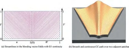
Fig. 5 Smooth, continuous streamline-like path generated on a compound surface with two patches using the streamline field based method.44

Fig. 6 Tool orientation in LCS.
2.4. Tool orientation optimization in workpiece coordinate system
Actually,when planning tool orientation,it not only considers the gouging and collision and machining strip width from the viewpoint of geometry,but also has to take the change of tool orientation along the whole tool path into account, as well its influence on the rotary axis motion of 5-axis machine tool.Thus, smoothing tool orientations has been becoming the focus of research, aiming to generate tool orientations with smooth transitions while ensuring no machining interferences.At first, the methods of smoothing tool orientations from the kinematics perspective are mainly conducted in the workpiece coordinate system (WCS) to control the change of tool orientation by adjusting the discrete tool orientations along the tool path.For example,Jun et al.proposed to smooth tool orientations in a feasible C-space, in which the requirements of the scallop height and the elimination of local gouging and global collision are satisfied.In the feasible C-space,the forward and backward searching algorithms were presented to search for two paths from the boundary of the feasible C-space,and then the one with relatively smaller angle change was selected as the optimal tool orientations for the purpose of better smoothness of the tool motion.In the method of Lauwers et al.,the drastic change of tool orientation was controlled by limiting the angle change per unit distance along the tool path. Ho et al.introduced the quaternion interpolation (QI), also called the spherical linear interpolation,to generate smooth tool orientations between the assigned key tool orientations. In QI based method,as shown in Fig.7(a),the tool orientations obetween two adjacent key tool orientations oand ocan be determined using the following formula:

where θ=arccos(o·o) is the angle between oand o,and n is the number of tool orientations to be interpolated between oand o. As shown in Fig. 7(b), QI based method can generate generally smooth tool orientation in WCS.
In the method proposed by Wang and Tang,the limitation of the angular velocity of the tool was taken into consideration, as well as the elimination of local gouging, and then gouge-free and angular-velocity-compliant tool orientations were generated,although also in WCS.In addition,as an effective way for tool orientation smoothing, the technique of the least square fitting and the format of dual NURBS or Bspline curve for tool path computation are widely adopted in literature.Recently, Sun et al.proposed to adjust the tool orientations under the constraints of maximum angular velocity, angular feed acceleration/deceleration, and jerk by utilizing the dual B-spline curves as the description of 5-axis tool path format. From several assigned key tool orientations using the radial basis function,the construction of the tool orientation field was first completed, and then tool orientations with smooth transition between any adjacent tool orientation were generated from the constructed tool orientation field.It has been noted by researchers that the tool orientations smoothed by the methods mentioned above can not necessarily guarantee smooth rotary axis motions in MCS due to the inverse kinematics transformation (IKT) of 5-axis machine from WCS to MCS, which is nonlinear, although they have been elaborately smoothed in WCS. The drastic fluctuations of the angular velocities, accelerations and jerks of the rotary axes of 5-axis machine would still exist, imposing heavy dynamics loadings on the rotary axes.
2.5. Smooth tool orientation in machine coordinate system

Fig. 7 Tool orientation smoothing using QI method.
As confirmed by recent researches,the kinematics performance of the rotary axes of 5-axis machine can be greatly improved indeed via the methods aiming to smooth the coordinates of the rotary axes in MCS, rather than those tool orientation smoothing methods in WCS. Thus, the MCS-based method to smooth tool orientations has gradually become the focus of research at present. Castagnetti et al.presented a novel concept of so-called DAO(Domain of Admissible Orientation) based on the principle of gouge-free and collisionfree, which was initially expressed in WCS and then transformed into MCS using IKT, as shown in Fig. 8. After that,a constraint optimization model was developed in an attempt to minimize the angle difference of the rotary axis and the curvature of its displacement curve. As a result, smooth tool orientations in MCS were gained by solving the constraint optimization model with gradient-based optimization method.Similarly, in the method proposed by Hu and Tang,after constructing the DGC (Domain of Geometric Constraints)at every path point, in which the satisfaction of the requirement of both local-gouging-free and scallop-height is guaranteed, a heuristic genetic algorithm was presented in detail to solve the constraint optimization model of tool orientation,which aims to control the angular accelerations of the rotary axes. In the method presented by Plakhotnik and Lauwers,the concept of admissible arc, which is illustrated in Fig. 9(a), was presented by regarding the tilt angle as the only variable to be modified in adjusting tool orientations,and then the Dijkstra’s algorithm was used to determine the optimal tool orientation at every path point for the purpose of minimizing the absolute values of the displacements of the rotary axes between two adjacent tool orientations. The schematic diagram of traversing the admissible arcs by Dijkstra’s algorithm is shown in Fig. 9(b). Related works motivated by the admissible arcs and using similar techniques can also be found in literature.
It is obvious that, smoothing tool orientations directly in MCS, while considering both the requirement of machining interference-free and the kinematics performance of 5-axis machine tool,is preferable.However,it is noticed that tool orientation smoothing in MCS constrained by the machining interference and the kinematics limits is not a trivial issue.Most of above methods suffer from a complicated and errorprone constraint optimization. Generally, the gradient based solution and the heuristic searching algorithm are popularly adopted in these works when dealing with such troublesome constraint optimization.But,since the feasible domains of tool orientation often occupy complex shapes and irregular boundaries, the constraints are usually difficult to be analytically expressed. It makes the solving process of the constraint optimization more complicated and difficult to solve.To address effectively this problem,Xu et al.proposed an alternate iteration strategy of first smoothing tool orientation and then checking the machining interference. In their method, the representative tool orientations(RTOs)are first specified in agreement with the requirement of interference-free, and then remaining tool orientations are interpolated from the specified RTOs by taking the minimum angular accelerations of the rotary axes as objective. Subsequently, the interference checking is done upon the interpolated tool orientations to detect possible newly arisen interferences.If the interference appears,the additional RTOs are fixed at the interference areas, and then the steps of smoothing and checking are performed again until no machining interferences occur.The flow chart of alternate iteration strategy for smoothing tool orientation is illustrated in Fig. 10. Since the motions of the rotary axes have become wholly smoother,this method can allow as less reduction of the feedrate as possible,thereby being able to provide a relatively higher real feedrate than the method that determines tool orientations only considering requirement of collisionfree.

Fig. 8 Domain of admissible orientation (DAO).73

Fig. 9 Method for optimal tool orientation based on admissible arc and Dijkstra’s algorithm.75
2.6. Recent performance oriented tool orientation optimization
The MCS-based methods can indeed guarantee smooth motions of rotary axes, thereby improving the machined surface quality. It is worth pointing out that the final machined surface quality is also reliant on the dynamic characteristics of 5-axis machining, including the cutting force, deformation,vibration and chatter. Based on this consideration, tool orientation optimization has been currently evolving from guaranteeing the avoidance of gouging and collisions, generating smooth motions of rotary axes, to the mechanics-based methods that focus on how to improve the cutting performance while the geometrical and kinematic constraints of 5-axis machining are respected.For example,by taking into consideration that the instantaneous tool-workpiece engagement is dominated by the tool orientation change, that the cutting speed of cutter and instantaneous chip thickness are also essentially affected by tool postures, as shown in Fig. 11(a)-(d),Layegh et al.investigated the effect of tool posture on the cutting force, torque as well as on the forced vibration of the flexible part, and then drew the mechanics-based reference maps for tool orientation selection in 5-axis ball end milling,as shown in Fig. 11(e) and (f), in order to help improve the machined surface quality. Sun and Altintasmade a further effort on discussing the influence of tool orientation on the presence of chatter in 5-axis ball-end milling, and then a chatter-free tool orientation optimization approach was proposed and experimentally validated with 5-axis milling tests.By considering the process dynamics constraints,Huang et al.proposed a tool orientation optimization method for 5-axis milling based on a minimax optimization principal. In addition, Altintas et al.further discussed the dynamics of machining process and presented related fundamentals of chatter stability laws.Moreover,Cordes et al.presented the modeling process of the chatter stability of robotic milling by using semi-discrete time and frequency domain methods. By considering the force-induced deformation effect in thin-wall milling operations, Sun and Jiangestablished an accurate predictive modeling of chatter stability for the dynamic milling system.Recently,Wang et al.developed a cutting performance maintained (CPM) method for adjusting tool orientations in 5-axis ball-end machining.With their method,the kinematics performance can be significantly improved while the expected cutting performance is also maintained as much as possible, and the precondition of interference-free in adjusting tool orientations is firmly obeyed.
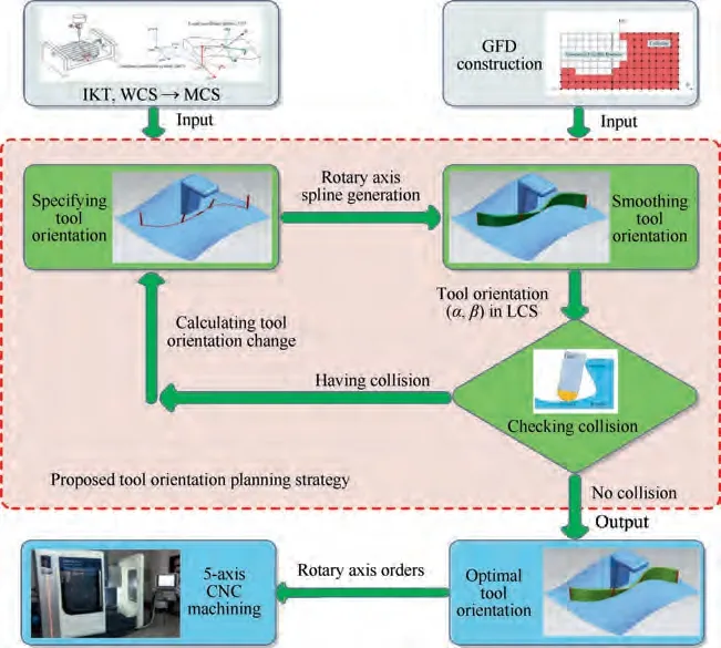
Fig. 10 Flow chart of alternate iteration strategy for smoothing tool orientations.78
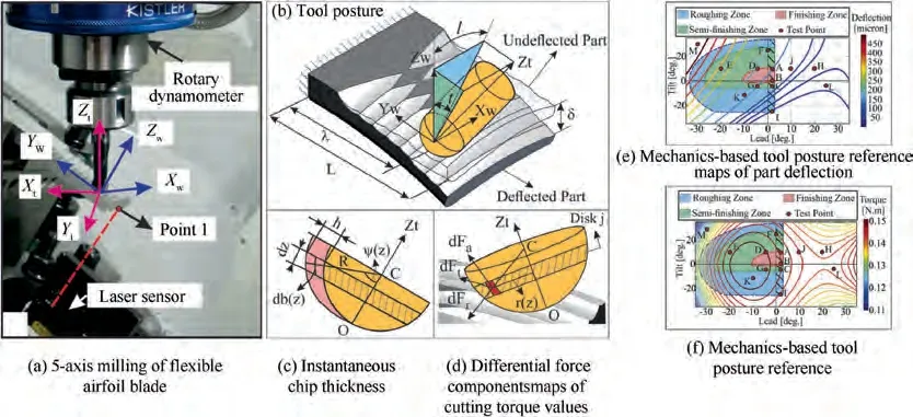
Fig. 11 Mechanics-based tool orientation selection for 5-axis ball-end milling of flexible parts.81
3. Adaptive feedrate scheduling for free-form surface machining
Feedrate scheduling that serves as a kernel of multi-axis motion systems, such as CNCs and robotic manipulators,etc.,plays a critical role in maximizing the machining efficiency and fulfilling the requirement of machining accuracy and quality. So far, many efforts have been conducted for scheduling feedrate in machining of free-form surface, and the results showed that undesired machining results, such as tool wear,tool breakage and excessive contour error caused by the limited servo tracking bandwidth,can be well controlled independently or combinedly via scheduling reasonably feedrate.According to the concerned machining related constraints,existing feedrate scheduling methods are roughly classified into the following three categories:
(1) Kinematics based feedrate scheduling (KBFS). This strategy is aimed at maximizing the real feedrate as much as possible while maintaining the kinematics constraints in terms of velocity,acceleration and jerk of cutter and drive axes within acceptable ranges. KBFS strategy can provide a reliable assurance of high machining efficiency and motion stability.
(2) Geometrics based feedrate scheduling (GBFS). For machining of high-precision parts, it is generally a basic requirement to bound the machining error within the required tolerance.For this purpose,the static arc length approximation error, namely chord error, and dynamic contour error, etc., are often controlled by means of GBFS.
(3) Cutting-force based feedrate scheduling (CBFS). Due to time-varying cutting conditions and cutter-workpiece engagement,accurate control of physical cutting process is challenging,especially in 5-axis machining.In order to meet the requirement of parts in surface topography,texture and internal stress, etc., CBFS receives great attention and is developed as one of the most effective approaches to ensure a stable cutting process.
Based on the above insight, the related works are reviewed as follows.
3.1. Kinematics based feedrate scheduling
For generating stable and time-optimized feed motion,motion control system not only requires a geometrically smooth and continuous tool path as input,but also needs to have the ability of preventing mechanical shock caused by excessive accelerations or jerks. For this purpose, the kinematics behaviors of CNC machine tool and robot in machining free-form surfaces can be controlled online or offline via KBFS. Compared with the traditional linear- and exponential-acceleration/decelera tion methods,S-shaped feed profile with piecewise constant jerk function has remarkable advantages in minimizing the drastic jump of acceleration and improving the timederivative continuity of the path-curve, thus S-shaped acceleration/deceleration methods are widely used in current multiaxis motion systems.Recently, some researches on parametric interpolators have demonstrated that the snapbounded and snap-continuous kinematic profiles have better performance in removing vibrations, compared with the Sshaped acceleration/deceleration methods. For example,Huang and Zhuand Wang et al.proposed independently snap-concerned feedrate scheduling methods and achieved expected results. From the view of constrained objectives, the KBFS methods above can be summarized as feedrate scheduling methods based on tool path kinematics,and the concerned constraints are mainly related with the tangential velocity,acceleration and jerk.However,the posture control of tool relative to workpiece is realized by coordinating all involved drive axes or manipulator joints, so the machined surface quality is also affected by the drive actuators’ kinematics performance.
To avoid constraint violation, an often used way in CNC machining is to consider the centripetal acceleration and jerk as additional constraints accompanied with the tangential kinematic constraints during the feedrate scheduling, but this manner is only applicable to 3-axis machining, especially, in robot-assisted manufacturing applications, the added redundant degree of freedom (DOF) and articulated serial structure make the relationship between the feedrate and joint kinematic properties become highly nonlinear. In order to solve this issue, Sencer et al.used cubic B-spline curve to describe the feeding profile and then proposed a generalized feedrate optimization model to convert the complicated constrained feedrate scheduling into solution of a set of inequality equations which can be tackled using sequential quadratic programming. By introducing a concept of the velocity limiting surface,a greedy jerk-limited feedrate scheduling algorithm is proposed,through which an analytical expression of the feedrate by solution of differential equations is obtained. Beudaert et al.proposed a decoupled model to separate the differential geometry problem from its temporal interpolation problem,and then presented a numerical optimization method to schedule the motion profiles with the constraints of drive axes and tangential jerks.In their work,to ensure the uniqueness of the solution, a dichotomy strategy is given to compute the intersection of the constraints at each interpolation time,as shown in Fig. 12. In addition, feedrate scheduling with drive constraints is also addressed by the well-developed smooth curve evolution method,bidirectional scanning strategy,finite impulse response (FIR) filtersand heuristic methods.
In order to further improve the solution of nonlinear optimization,linear programming algorithm is adopted widely for feedrate scheduling due to its faster convergence and lower computation cost. Considering that it is difficult to linearize the constraints of jerks with the primary feedrate, the square of feedrate, f, is often taken as the optimization variable in feedrate scheduling. For example, after approximating the nonlinear constraint of jerk with its upper bound,Fan et al.proposed a linear programming based time-optimal feedrate scheduling method for five-axis machining, through which an approximate global optimal solution is found by a polynomial time algorithm with guarantied computational complexity.Based on this work, Guo et al.established an implicit expression between servo dynamic tracking error and feedrate,which is approximated as a linear combination of the acceleration and the jerk, so that the constraint of servo tracking error can be also bounded using linear programming. Afterwards, Erkorkmaz et al.merged the linear programming based formulation with a novel parallel windowing technique,and proposed a two-step solution based feedrate optimization method, as shown in Fig. 13. Erkorkmaz’s method is able to handle very long toolpath and produces the jerk-limited feedrate profile for each individual windowed portion in realtime with minimal complexity.Lately,Sun et al.proved that the constraints of machines axis velocities, accelerations and jerks as well as the tangential jerk constraints of cutter tip are capable of being approximated as a linear function of the primary feedrate f, and proposed a piecewise feedrate optimization method with Ccontinuity assurance for adjacent B-spline feed profiles connection. This method not only gives accurate analytical solution of the feedrate with linear computation complexity, but also has a strong controllability in limiting axis accelerations and jerks.
3.2. Geometrics based feedrate scheduling
Feedrate-related geometric errors mainly include two categories: the static chord error and the dynamic contour error,as mentioned in Section 3.1. The static error is induced due to approximating the desired path curve with the chord. For an arbitrary parametric path, such theoretical error generally need be bounded from the source, so that its adverse effect on the path tracking accuracy of servos can be brought under control. Theoretically, there exists a proper feedrate upper limit to avoid the chord error exceeding the prescribed tolerance. For example, by approximating the local desired tool path with an osculating circle that has identical curvature radius, Yeh and Hsuderived an explicit quadratic functional relationship between chord error and feedrate,and then developed the classical adaptive interpolation algorithm, by which the feedrate can be automatically adjusted so as to fulfill the tolerance requirement.To improve the estimation accuracy of chord error, Du et al.took the influences of the torsion and curvature variation into account, and proposed a thirdorder approximation method for chord error calculation. It is worth pointing out that due to dynamic mismatch,response delay of servo drives as well as some external disturbance,excessive contour error, also called as dynamic contour error,which is defined as the shortest distance from the real cutter location to the desired path, might still occur when it comes to the machining process of tool path with tight curvature.This implies, it is far from enough to depend on only constraining the chord error to guarantee high machining accuracy. In fact, it is a more significant and challenging task to restrict the contour error rather than the chord error. Assuming that there is no mismatch among all involved axes, Lin et al.represented the contour error as a nonlinear function of feedrate, and on basis of that, a maximum allowable feedrate with confined contour error can be achieved by solving a sextic equation.Subsequently,Jia et al.and Wang et al.approximated the whole feed drive as a second order underdamped system, and then the satisfaction conditions of the error constraint is yielded. In their work,the error-limited feedrate can be calculated analytically by solving a linear inequality,which reduces significantly the problem complexity and improves the computational efficiency. However, the above-mentioned methods are only dedicated to 3-axis machining, and most feedrate scheduling strategies designed for 3-axis contouring control cannot be directly applied to 5-axis machining due to the nonlinear kinematics between the Cartesian space and the joint space.
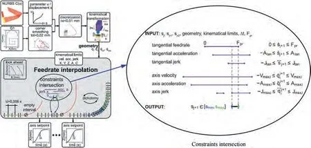
Fig. 12 Velocity profile optimization based dichotomy strategy and constraint intersection.96

Fig. 13 Erkorkmaz’s method. Optimized feed profile for a long tool path and its local windowed portion, considering zero boundary conditions.104
As shown in Figs. 14, 5-axis contouring errors consist of tool tip contour error and tool orientation one. In 5-axis machining, apart from an accurate following of tool tip path,it is also necessary to keep the tool orientation contour error within the required tolerance. Otherwise, excessive tool orientation deviation,especially in flank milling with cylindrical cutter, may lead to an undesired gouging and collision, thus degrading the final accuracy of the milled parts. In order to realize 5-axis contouring control,the following two issues have to be fully addressed:
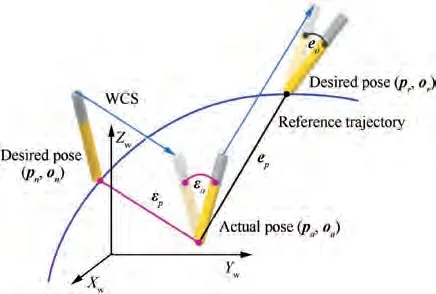
Fig.14 Schematic diagram of the tracking error and contouring error of cutting tool in 5-axis machining tasks.111
(1) Constructing the nonlinear mapping relationship between the tool tracking error and axis tracking error,which are defined in WCS and MCS, respectively.
(2) Formulating the estimation model of the axis tracking error, tool tracking error and contouring error with respect to the primary variable feedrate.
By integrating the kinematic Jacobian function and the steady-state response of servos, Chen et al.first established an approximate linear relationship between axis tracking error and tool tracking error for general five-axis serial machines.On this basis, an explicit formula for computing the feedrate upper limit with confined contour errors was derived by introducing a shifted Frenet frame,through which the synchronous control of the tool tip contour error and the tool orientation error can be easily realized. By modeling the physical cutting load as a torque disturbance to servo drives, Yang et al.conducted an in-depth investigation of feedrate on 5-axis contouring control, and provided an efficient feedrate scheduling method for more accurate path contouring with vibration avoidance. In addition, related works and methods, such as the offline gain adjustment approach,feedforward trajectory command shapingand contour error precompensation,etc., were also proposed and demonstrated to be well-performed in terms of contouring error control when combined with the existing feedrate scheduling.
3.3. Cutting-force based feedrate scheduling
As illustrated in Fig. 15, it has been confirmed that the mechanical wear and energy consumption in machining can be effectively reduced by controlling reasonably the cutting force,thereby improving the machining efficiency,while feedrate plays an important role among all parameters related to cutting force.Some commercial CAD/CAM systems have integrated the feedrate scheduling functionality, most of them are basically dependent only on geometric and volumetric analysis,in which feerate is assumed to be proportional to the average or instantaneous material removal rate(MRR),not related to the process of physical machining yet.When adopting these MRR-based CAM softwares to generate NC programs, it is difficult to realize the accurate control of instantaneous cutting force.As a result,operators have to set a conservative feedrate command along the tool path to avoid excessive tool deflection, wear and breakage, thus sacrificing the machining efficiency.
To address this problem, using the modeling kernel of CAD/CAM softwares, Li et al.developed a solid-modelbased process simulation system, through which the cutting force can be predicted by using an empirical model and controlled by a segmented feedrate optimization scheme. Using the discrete Z-map model, Guzel and Lazoglupresented a new computationally efficient algorithm for the cutting force prediction, and introduced a piecewise variable feedrate scheduling strategy for ball-end CNC milling. By analyzing the variation of the uncut chip thickness along different feed directions, Erdim et al.presented an analytical calculation model of cutter-workpiece engagement, and revealed an approximate linear relationship between feerate and resultant cutting force, which was then used for the constant-force process planning. Further,taking the cutter runout into consideration, Ko and Chodeveloped an analytical feedrate scheduling algorithm for ball-end milling, in which the reference cutting force is computed based on the transverse rupture strength of the tool material. Note that, the cutting edge of indexable end mills is not a continuous geometry, their run out parameters may be different at different insert layer. As an improvement, Kim et al.established a mechanistic cutting force model with additional benefit of minimizing the influence of cutter runout, deflection and cutting coefficients variation.For assurance of the optimality of feedrate scheduling, Zhang et al.took the stochasticity of machining allowance into consideration,and also proposed an off-line feedrate scheduling method by referring the measured real force instead of the predict one,greatly reducing the complexity of problem and also avoiding the complicated calibration of mechanical cutting force coefficients.
For the flank milling, Ko et al.applied the virtual CNC technique to the physical cutting process control, and proposed an optimal feedrate scheduling method in order to make the average cutting force close to the reference value without causing saturation of the drives. By introducing a concept of the cutting force-area quotient function, Xu et al.proposed a 5-axis tool path generation algorithm that strives to globally maximize feedrate for an arbitrary free-form surface while respecting a given deflection cutting force threshold, in which the effect of the adjacent already-cut-groove on the deflection cutting force is also incorporated. Nevertheless, to realize the precise control of cutting force, time-consuming iteration is often necessary for the prediction of cutting force and modulation of feedrate. To simplify the calculation, Wang et al.proposed a new solution of the instantaneous chip thickness using least squares theory, and established an explicit analytical expression of the cutting force for each CL point, thereby reducing the calculation complexity. On basis of this, an efficient feedrate scheduling strategy is proposed.
4. Trajectory planning
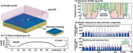
Fig. 15 Feedrate optimization for free-form milling considering constraints from the feed drive system and process mechanics.116
Different form CNC machine tools that have generally unique inverse solution from WCS to MCS, robotic manipulators’inverse kinematic solutions from the operational space to the joint space are not unique due to redundant joint.This implies that the same feedrate will correspond possibly to different velocities,accelerations of robot joints.In addition,in applications such as spot welding, assembly and transportation, etc.,the requirement for the end effectors is only to pass through all the specified points, and the tool path tracking errors may not be the main concern, which is totally different from that of feedrate scheduling of CNC machining. Thus, apart from automatic tool path generation methods and feedrate strategies,robot machining also pays more attention to trajectory planning,namely motion planning of joint with respect to time,since the demanded actions of robot end effector have to be realized by corresponding joint commands. To sidestep the problems caused by frequent real-time IKT and kinematic singularities, trajectory planning of robotic manipulators is currently focused on planning joint displacements, velocities,accelerations and jerks, with the kinematic and dynamic constraints imposed on each joint.Since multi-joint industrial robots are mainly applied in such manufacturing processes such as spot welding, assembly and transportation,etc., which only care about the end effectors being able to accurately move from one point to another. In general, this type of point-to-point(PTP)joint trajectories usually compose of cubic or quintic polynomial curve with Ccontinuity, high degree Bezier curve, or cubic or quintic B-spline curve.Therefore, the joint trajectory planning of robotic manipulators becomes a nonlinear constrained optimization problem which aims to search for the optimal displacement-time curves of the joints under the constraints of the joint kinematic and dynamic characteristics,such as the limits of velocities,accelerations, jerks and torques for each link of the kinematic chain,as well as the continuity conditions for the velocities and accelerations along the planned tool path.
To address this challenging problem of PTP trajectory planning, time-optimal models,minimum-energy models,minimum-jerk models,and multi-criteria models,such as optimal time-jerk,or optimal time-energy models,etc.,are proposed successively.Various nonlinear constraint optimization techniques,such as convex optimization, dynamic programming, sequence quadratic programming, genetic algorithm and swarm intelligence algorithm,have been correspondingly developed to cope with such constrained optimization problems. It is noticed that, in PTP trajectory planning,the end effectors of the robotic manipulators can accurately reach the prescribed demanded target points in the task space, thus they are mainly dedicated to the repetitive positioning tasks like automatic assembly, palletizing, drilling, transportation, etc., where the movement of end-effector is free between the target points, as shown in Fig.16(a).In the situations,due to the nonlinearity of the kinematic transformation between the joint space and the task space, it is generally difficult to foresee the trajectory in the task space of the end effector between the target points in advance. This makes the PTP trajectory planning methods not to be directly applied to machining tasks with continuous tool path, such as free-form surface milling and polishing that have strict requirement for tool path tracking errors.
For continuous path(CP)machining tasks,due to the functional redundancy of robotic configuration and nonuniqueness of IKT solution, trajectory scheduling in joint space by considering the physical capabilities of actuators while respecting the required path tracing accuracy of end effector, is still challenging for robot machining applications.To address this issue,Olabi et al.presented a method of trajectory planning for robot machining with CP by means of finite-impulse response filtering of the toolpath in operational space,however,for avoiding violating the joint kinematic limits, the operation of time-consuming constraints checking has to be performed iteratively for the feedrate updating.Recently,Wang et al.began to take the limit of velocity of the end effector in task space into the consideration of the trajectory planning in the joint space for CP robotic machining. Bianco and Ghilardelliproposed a path tracking algorithm considering the kinematic constraints of the end effector in the task space. By means of a local path filter, Dai et al.presented a greedy algorithm to plan the jerk-optimal trajectory with discrete time constraints,and for guaranteeing a computationally efficient collision detection when machining free-form parts with complex shapes, a learning-based collision estimator based on an adaptive sampling strategy was also introduced.By minimizing the weighted square sum of the joint accelerations, Peng et al.formulated the complex resolution of robot functional redundancy into a constrained optimization problem, and presented an efficient sequential linearization programming (SLP) based optimization method for smooth joint movement generation while simultaneously considering the constraints of joint limitation, motion singularity avoidance and stiffness.It is worth pointing out,to realize the accurate CP path tracking in the task space for free-form machining, as shown in Fig. 16(b), joint trajectory planning has to take the path tracking error and the feedrate of the end effector into account at the same time. Meanwhile, the planned feedrate profile of end effector also must meet the specific demands concerning the path tracking accuracy, and the velocity, acceleration and jerk of robotic joints, thereby guaranteeing the high-efficiency machining of free-form surface.
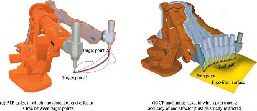
Fig. 16 Trajectory planning for robotic manipulators.
5. Summary
In this paper, a review of the essential issues in machining of free-form surfaces, as well as their corresponding current research statuses, has been carried out. Three major issues,i.e., tool path generation, feedrate scheduling in Cartesian space and trajectory planning in joint space for both CNC machining and robot machining, have been considered. It is observed that numerous techniques and methods have resulted in significant developments and improvement in these aspects,however some challenging issues still need to be further studied in depth so as to improve the machining quality and efficiency of free-form surface.Based on the analysis of research progress in the three issues presented in previous sections, the conclusions, remaining challenges and future directions in this field of free-form surface machining could be:
(1) Most of CC path construction methods are still limited to the point-by-point design mode at the purely geometric level,the whole distribution pattern of the path relies heavily on the initial CC path and these methods also lack the ability of integrating effectively the geometric and physical characteristics. Recently proposed vector field based CC path planning are considered a new route that can reconcile the preferred cutting directions at local CC points with the topography demands of overall paths. Moreover, vector field based methods are also more promising in CC path planning compared to the traditional methods, due to the breakthrough of taking geometric and dynamic characteristics, and even the physical performance requirements of the free-form surface parts into consideration.
(2) For tool orientation planning of machining free-form surfaces, it is desired to improve the kinematics and dynamics performance of the rotary axes of machine tools while the geometric constraints are respected. At present, the methods of planning the tool orientations have evolved from eliminating the gouging and collisions, improving the kinematics performance, to the mechanics-based methods that devote to optimize the process performance. To exploit fully the potential of machine tools and robots and improve the machining efficiency and quality of free-form surfaces, all involved factors, such as machining interferences, singularity,kinematics limits,cutting force,machining deformation,chatter and other dynamic characteristics, etc., should be further studied, such that they can be incorporated in planning tool orientations.
(3) For feedrate scheduling, affected by many factors including but not limited to time-varying cutting condition, position/time-dependent property of geometric error, and external nonlinear disturbance, it is still difficult to describe the relationship between the contour error and feedrate using accurate mathematical model. Most of existing feedrate scheduling strategies for 5-axis parametric interpolators remain in the offline solution stage, their extensibility and robustness are also an issue worthy of study. Moreover, how to realize the seamless integration of CAM/CNC machining path information and develop a feedrate scheduling kernel with good compatibility and strong robustness has important significance for the development of a new generation of intelligent CNC machining systems.
(4) For trajectory planning,most of current research works are mainly focused on PTP trajectory planning which is difficult to be directly applied to machining of free-form surfaces with continuous tool path due to the uncontrollable path tracking error of PTP trajectory. When it comes to free-form surface machining, trajectory planning of robot manipulators must consider the path tracking error and the feedrate of end effector simultaneously. The planned trajectory for joint and feedrate profile for end effector have to meet the specific demands concerning the path tracking accuracy, and the velocity, acceleration and jerk limits of robotic joints, thereby ensuring the stable and efficient machining process and realizing the high-performance machining of free-form surfaces.
The authors declare that they have no known competing financial interests or personal relationships that could have appeared to influence the work reported in this paper.
This study was partially supported by the National Natural Science Foundation of China (Nos. 91948203, 51975097) and the National Key Research and Development Project (No.2020YFA0713702) to Dalian University of Technology. The authors thank the anonymous reviewers for their valuable suggestions and Dr. Lei Wu of Dalian University of Technology for his help in manuscript editing and proofreading.
 Chinese Journal of Aeronautics2022年8期
- Chinese Journal of Aeronautics的其它文章
- Active, compact, wideband, receiving filtenna with power adaptation for space-limited wireless platforms
- Deployment of SMP Miura-ori sheet and its application: Aerodynamic drag and RCS reduction
- Beam tracking method based on reconfigurable intelligent surface for obstructed communication
- An alternative method to reduce process-induced deformation of CFRP by introducing prestresses
- Novel orbit-attitude combination mode for solar power satellites to reduce mass and fuel
- Synthetic damage effect assessment through evidential reasoning approach and neural fuzzy inference: Application in ship target
