
Intrinsically zincophobic protective layer for dendrite-free zinc metal anode
2022-06-20 08:00ChunlinXieQiZhngZefngYngHuiminJiYihuLiHunhunLiLingFuDnHungYougenTngHiynWng
Chinese Chemical Letters 2022年5期
Chunlin Xie, Qi Zhng,*, Zefng Yng, Huimin Ji, Yihu Li, Hunhun Li, Ling Fu,Dn Hung, Yougen Tng, Hiyn Wng,,*
a Hunan Provincial Key Laboratory of Chemical Power Sources, College of Chemistry and Chemical Engineering, Central South University, Changsha 410083,China
b School of Chemistry and Chemical Engineering, Henan Normal University, Xinxiang 453007, China
c College of Materials Science and Engineering, Chongqing University, Chongqing 400045, China
d Guangxi Novel Battery Materials Research Center of Engineering Technology, School of Physical Science and Technology, Guangxi University, Nanning 530004, China
Keywords:Zinc metal anode Zinc dendrites Barium-titanate Protective layer Intrinsically zincophobicity
ABSTRACT Aqueous zinc anodes have attracted the attention of many researchers owing to their high safety, low cost, and high theoretical specific capacity.However, its practical application is severely limited by the dendrite growth on zinc anode.Herein, we develop an intrinsically zincophobic barium-titanate protective layer with a porous structure to suppress the zinc dendrite formation by homogenizing the ion distribution on the anode surface, increasing the nucleation sites, and limiting the irregular zinc growth.Based on these synergistic effects, the coated zinc anode can exhibit long cycle life (840 h at 0.5 mA/cm2 for 0.5 mAh/cm2) and low voltage hysteresis (36 mV).This work can provide a feasible direction for the design of intrinsically zincophobic coating materials to uniformize the zinc stripping and plating.
Lithium-ion batteries (LIBs) using organic electrolytes have developed rapidly in the past two decades owing to the high energy and power density.However, their further applications in largescale energy storage systems are limited by the hidden safety hazards and high production costs [1–4].Therefore, it is urgent to develop alternative electrochemical systems for lithium-ion batteries [5,6].Aqueous zinc-ion batteries (AZIBs) have attracted more and more attention in recent years owing to their environmental friendliness, safety, low cost, high theoretical specific capacity(820 mAh/g), and low electrode potential (-0.76 Vvs.standard hydrogen electrode) of zinc metal [7–10].The big progress has been made in the cathode materials of AZIBs (such as Li+intercalated V2O5·nH2O,in-situcarbon reduced Mn3O4and self-doped polyaniline cathode) [11–13].However, compared with the development of cathode materials, zinc anodes suffer from inescapable issues,such as the dendrites, corrosion, and hydrogen evolution reactions[14,15].Among them, the capacity attenuation and short circuit problems caused by dendrites are fatal to the practical application of zinc-ion batteries [16–18].Some modifications based on the following eq.1 have been proposed for addressing the dendrite problem:

As seen clearly, the key factors affecting zinc deposition include the zinc ion distribution, the interfacial electric field, and the spatial location of zinc growth.That is, a dendrite-free zinc deposition process can be achieved when there are more uniform electron-ion distribution, easier electron-ion exchange process, and more regular growth direction on the reaction interface.A suitable interfacial coating strategy can introduce the above modification effects on zinc anode [19].For example, the porous nano-CaCO3coating, and nano-ZnO coating can adjust the uniformity of ion transmission and electric field distribution at the electrode interface [20,21].The UiO-66 MOF solid electrolyte coating can optimize the zinc nucleation process by nanoscale wetting effects [22].However, the interaction between the coating layer and zinc is insufficiently investigated in these works.Herein, the binding energy of zinc on different coating layers is proposed to differentiate their zincophobicity and zincophilicity.Generally, if the interaction is lower than that between the zinc crystal plane and zinc atoms, the zinc can be guided to deposit under the coating, indicating a huge diffi-culty to puncture the coating during zinc growth.If not, the zincophilic coating layer will induce the direct deposit of zinc dendrites on its surface, leading to the rapid failure of coating layer.In our previous work, (001) exposed TiO2protective layer was specially designed by hydrofluoric acid assisted hydrothermal method to achieve dendrites-free zinc metal anode due to the zincophobic crystal orientation [23].Note that the normal TiO2tends to form(100) exposed plane, which is zincophilic based on the density functional theory (DFT) calculation.Therefore, it is of great significance to find some new protective coating materials with intrinsic zincophobicity to achieve more stable zinc anodes without special design.
In this work, we first evaluate the interactions between zinc and barium-titanate (BT) by density functional theory (DFT) calculation, which indicates that (100) and (110) facets of bariumtitanate exhibit strong zincophobicity.These crystal facets dominantly exist in common barium-titanate, that is, it can be a perfect intrinsically zincophobic protective layer.As a result, the modified zinc anode with commercial barium-titanate can exhibit dendritefree morphology, long cycle life, and low voltage hysteresis by adjusting the electric field and ion distribution at the zinc anode interface to restrict the uneven zinc deposition.Moreover, an aqueous Zn||MnO2full battery assembled with barium-titanate protective anode can deliver high specific capacity and capacity retention ratio.
The X-ray powder diffraction (XRD) patterns (Fig.1a) indicate that the dominant crystal facets of zinc foil are (100), (101) and(102) facets and those of commercial barium-titanate particles are (100) and (110) facets.The transmission electron microscopy(TEM) characterizations were conducted to further elucidate the crystal structure of barium-titanate.The lattice spacing of about 0.28 nm and 0.4 nm can be observed in the high-resolution transmission electron microscopy (HRTEM) image, which is well indexed to (110) and (100) crystal facet of barium-titanate, respectively (Figs.1b and c).The well-crystallized nano barium-titanate can be verified by the corresponding selected area electron diffraction result (Fig.S1 in Supporting information).Afterward, the interactions between zinc atom and these dominant crystal facets are simulated by DFT method.The calculated binding energy and the corresponding model are shown in Figs.1d-g.
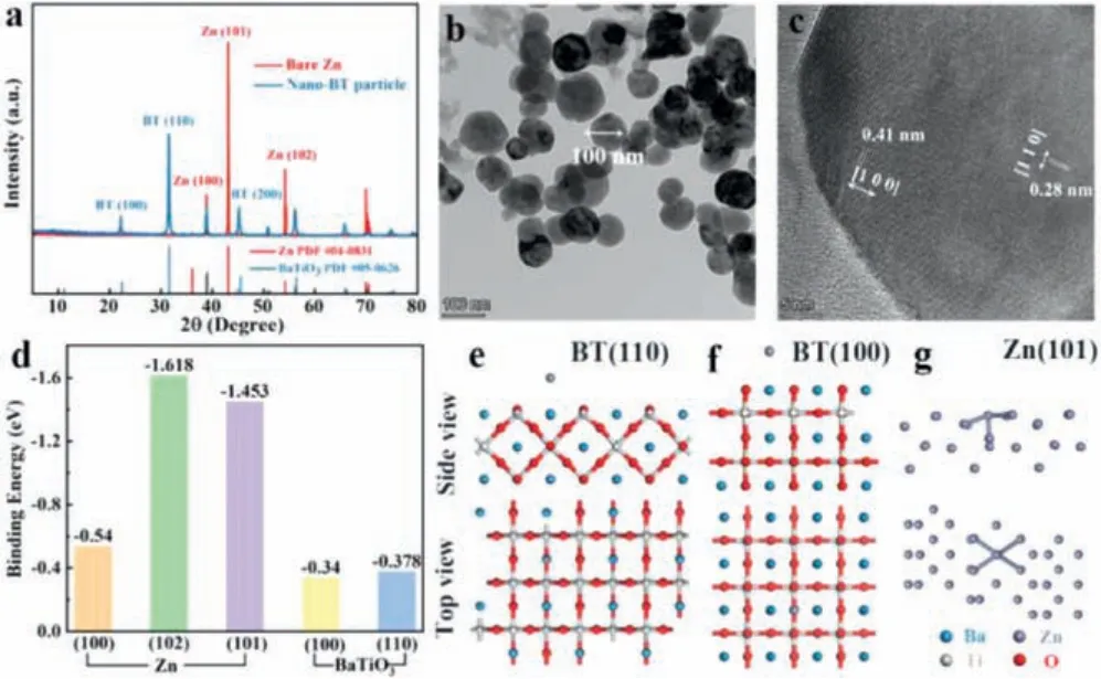
Fig.1.(a) XRD patterns of zinc foil and nano barium-titanate.(b, c) TEM images of barium-titanate.(d) Calculated binding energies of zinc atom with different facets.Calculation models of zinc absorbed on (e) BT (110) facet, (f) BT (100) facet and (g)zinc (101) facet.
As seen clearly, the binding energies of the binding energies of zinc atom on barium-titanate (100) and (110) crystal facets(-0.34 eV and -0.378 eV) are both lower than those of zinc atom on dominant zinc facets (-0.54 eV, -1.618 eV and -1.453 eV),which indicates that zinc prefers to deposit on zinc substrate in comparison to the barium-titanate layer, in another word, the as-prepared barium-titanate layer is intrinsically zincophobic.It should be noted that the zinc atom with the lowest binding energy is adsorbed on the apex of the octahedron composed of oxygen and barium atoms, indicating that the zincophobicity of bariumtitanate is mainly due to the strong repulsive force generated by large radius Ba2+against zinc atoms [23,24].In contrast, the high binding energy between zinc atom and zinc facets can be ascribed to the strong metal bond [25].Accordingly, the commercial barium-titanate can be considered as a perfect interface protective layer for zinc anodes, which can adjust the electric field and ion distribution at the zinc anode interface and restrict the zinc deposition by strong zincophobicity.
A uniform and porous barium-titanate protective layer was coated on zinc anode by a simple blade coating method (Fig.2a).The cross-sectional SEM image and energy dispersive X-ray (EDX)mapping image of as-prepared zinc anode illustrate that the thickness of the coating layer is about 8 μm (Fig.2b, Figs.S3c and d in Supporting information).Brunauere-Emmette-Teller (BET) test results show that the pore volume density of the coating is 2.787 × 10⁻²cm3/g in the range of 2–10 nm (Fig.S2 in Supporting information).Compared with two-dimensional surface of smooth zinc foil, the three-dimensional porous coating layer can provide more ion transport channels and regulate ion flux, uniformize the zinc deposition [21].The contact angles of the electrolyte on the bare zinc and BT coated zinc are 99.9° and 72.4° (Fig.2c), respectively, indicating the better wettability of coated anode, which can improve the kinetic process of zinc ions at the electrode interface and reduce the ions transmission impedance [22].The faster ion transport may be related to the strong space charge polarization of barium-titanate [26–28].The lower ion transmission impedance of the coated anode is also proven by electrochemical impedance spectroscopy (EIS) results (Fig.2d, Table 1).The capacitance (C)is obtained by calculating the slope of theic-v(currentvs.scan rate) curves, and theicis the half value of current difference between positive and negative scanning at 0 V (Fig.S4 in Supporting information) [29].As seen in Fig.2e, the interface capacitance of BT coated zinc (110.2 μF/cm2) is much higher than that of the bare zinc (38.57 μF/cm2), indicating the stronger adsorption ability of zinc ions on the coated zinc anode (The adsorption site is at the junction of coating and zinc foil).The enrichment of zinc ions on the electrode interface can provide more nucleation sites for zinc deposition, thereby optimizing the uniformity of deposition[20].Its lower corrosion current effectively demonstrates the better anti-corrosion ability that can inhibit the generation of the byproduct, thereby maintaining uniformity of ion transmission and improving the zinc anode utilization [14,30].
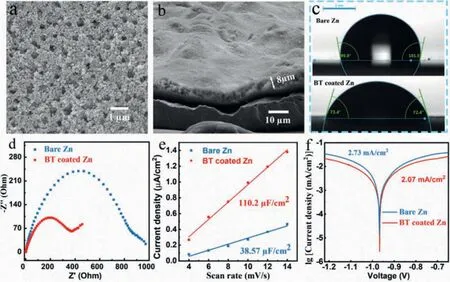
Fig.2.SEM images of coating (a) surface and (b) cross section.(c) Contact angles of electrolyte on bare zinc and BT coated zinc anodes.(d) EIS curve and fitting circuit diagram of Zn||Zn symmetric batteries.(e) Capacitance fitting curves of Zn||Zn symmetric batteries.(f) Linear polarization curves displaying the corrosion on bare zinc and BT coated zinc anodes.
The zinc deposition processes on different anodes are illustrated in Fig.3a.Zinc prefers to deposit at the tip sites and the sites with high ion concentration on bare zinc electrode.These sites distributed unevenly and sparsely on the electrode interface can induce the zinc dendrites formation during the repeated cycles.When using barium-titanate as the protective layer, zinc ions can be enriched on the electrode surface to provide more nucleation sites for zinc deposition, so that the ion flux and electric field strength on the electrode surface are evenly divided.The layer with strong zincophobicity (such as “gold armor”) can also homogenize zinc deposition by guiding zinc to grow beneath the layer.The Zn||Cu half batteries were employed to further test the reversibility and Coulombic efficiency of zinc deposition/stripping.As shown in Fig.3b, the zinc nucleation overpotentials on bare Cu and BT coated Cu in the first deposition are calculated to be 42 mV and 30 mV, respectively.The lower overpotential of BT coated Cu indicates that the coating layer can provide more activated nucleation sites for zinc deposition [31].The Cu electrode coated by BT exhibits much longer cycle life (500 hvs.60 h) and lower voltage polarization (54 mVvs.69 mV at 25th cycle) compared with bare Cu at a current density of 2 mA/cm2(Figs.3c and d, Fig.S5 in Supporting information).When decreasing the current density to 0.5 mA/cm2and the specific capacity to 0.5 mAh/cm2, the modified anode can still deliver excellent reversibility (Fig.S6 in Supporting information).The Cu electrode was extracted from the cell after 10 cycles for further morphology observation.As seen, the zinc deposition under the coating is more homogeneous than that on bare Cu foil because there are only few active sites on Cu foil,which may lead to the formation of a large amount of “dead zinc”and cause the battery to short circuit (Fig.S7 in Supporting information).Meanwhile, the binding energies of the (100) and (110)crystal facets of Cu with zinc are calculated by DFT (Fig.S8 in Supporting information), indicating the zincophilicity of copper host.However, zinc dendrites can be still induced on the zincophilic Cu due to its uneven ion distribution and disordered growth direction[32] .For comparison, it is interesting to note that the zinc can be guided by the porous and zincophobic coating layer to uniformly nucleate and grow on the electrode surface, thereby obtaining a dendritic-free electrode.
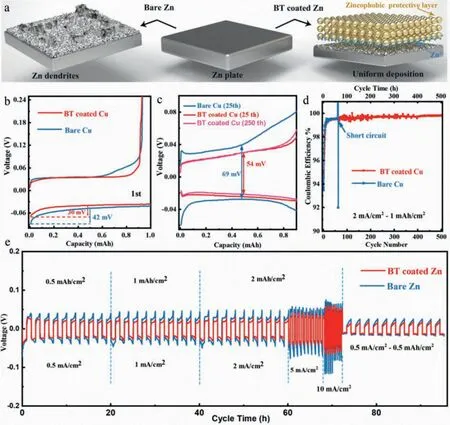
Fig.3.(a) Schematic diagram of zinc deposition for different anodes.The electrochemical performance of Zn||Cu half batteries capacity-voltage curves of the (b) first cycle and (c) 25th cycle, (d) Coulombic efficiencies.(e) Rate performance of Zn||Zn symmetric batteries.
In Fig.3e, the superior rate performance of the BT coated zinc anode with a lower voltage hysteresis and more stable voltage plateau can be observed when the current density is increased from 0.5 mA/cm2to 1, 2, 5, 10 mA/cm2, whereas the bare zinc breaks down at 10 mA/cm2, indicating that the easier electronion exchange process and more uniform stripping/deposition of the BT coated zinc anode.The surface morphologies of the cycled anodes after 10 cycles are shown in optical pictures and SEM images(Fig.4a, Figs.S9a and b in Supporting information).The coated anode is intact without the generation of "island-like dendrites" and the well-defined distribution of Ti, Ba and Zn in the EDX mapping image also proves that the coating layer can protect the separator from being pierced by restricting the zinc growth (Figs.4b and c).Furthermore, the barium-titanate coating layer on the cycled anodes was removed by using methyl-2-pyrrolidinone (NMP)to dissolve polyvinylidene difluoride (PVDF) in the coating layer.Fig.4d and Fig.S8d show the morphology of zinc deposition under the coating.No dendrite is observed and the surface remains flat, which is in sharp contrast with the dendritic deposition on bare zinc (Fig.S9c in Supporting information).In the long-cycle symmetric batteries test, profited from the adjustment of zinc deposition by the protective layer, the BT coated zinc can be operated steadily for more than 840 h at 0.5 mA/cm2for 0.5 mAh/cm2,which is much superior to the bare zinc (60 h), and it also exhibits a low voltage hysteresis (36 mV at 20thcycle) and stable voltage plateau (Fig.4e).When increasing the current density to 2 mA/cm2and the specific capacity to 1 mAh/cm2, the coated anode can still deposit and strip for 400 h while the bare one shows the quick failure of 60 h (Fig.S10).The positive role of this intrinsically zincophobic barium-titanate protective layer in improving anode stability has been well proven through the comparison of the symmetrical battery electrochemical behaviors.
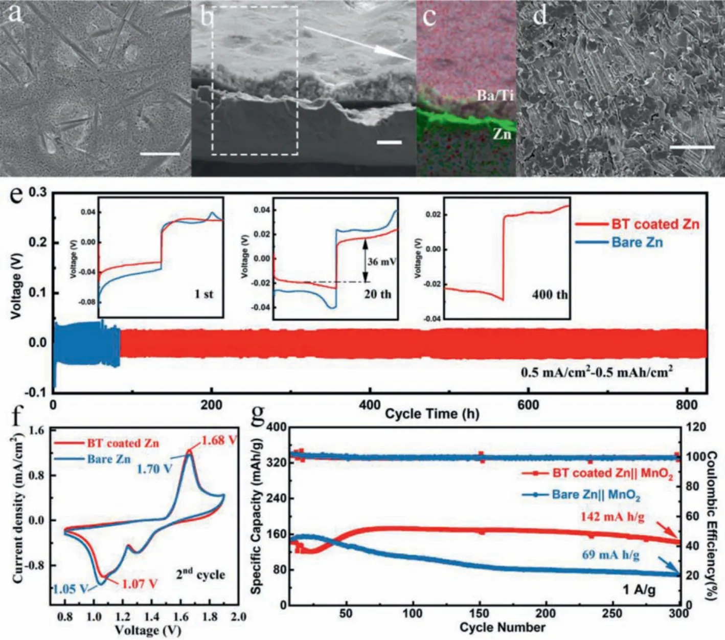
Fig.4.The SEM images of BT coated zinc anode (a) surface, (b) cross section, (c) corresponding EDX mapping image, (d) without coating layer, cycled at 0.5 mA/cm2 with a capacity of 0.5 mAh/cm2 after 10 cycles.(e) Cycling performance of Zn||Zn symmetric batteries at 0.5 mA/cm2 for 0.5 mAh/cm2.Cyclic voltammetry curve (f) and cycling performance (g) of the full batteries at a current density of 1 A/g.Scale bar:10 μm.
The full battery was assembled with BT coated zinc anode and the fibrousβ-MnO2cathode synthesized by previous (Fig.S11 in Supporting information) [7].As shown in cyclic voltammetry (CV)curves (Fig.4f), the BT coated Zn||MnO2battery exhibits higher reduction peak (1.07 Vvs.1.05 V) and lower oxidation peak (1.68 Vvs.1.70 V), indicating the faster Zn2+kinetics and the higher deposition/stripping efficiency, which is in consistent with the EIS results (Fig.S12a in Supporting information).The long-term cycling performance of the batteries cycled at 1 A/g are depicted in Fig.4g and Fig.S12b (Supporting information), from which the battery with BT coated zinc anode exhibits much better cycling stability with a specific discharge capacity of 142 mAh/g remaining after 300 cycles compared with that of bare one (69 mAh/g).The excellent performance of the full battery certifies the practical value of this protective layer.
In summary, a porous and intrinsically zincophobic bariumtitanate protective layer was proposed to stabilize zinc anode.Benefitting from the strong repulsive force generated by large radius Ba2+against zinc atoms, the commercial barium-titanate exhibited strong zincophobicity and the zinc ions showed strong adsorption at the zinc anode interface.Accordingly, this coating layer played an important role in regulating ion transport, zinc nucleation and zinc crystal growth.Based on these synergistic effects,the as-prepared zinc anode showed superior reversibility of zinc stripping/deposition with a long lifespan (840 h) and a low voltage hysteresis (36 mV) at 0.5 mA/cm2for 0.5 mAh/cm2.This work provides a novel guiding direction for discovering naturally zincophobic protective layer materials to modify zinc anode interface,which can be also extended to other metal anodes.
Declaration of competing interest
The authors declare that they have no known competing financial interests or personal relationships that could have appeared to influence the work reported in this paper.
Acknowldgments
This research was financially supported by National Nature Science Foundation of China (Nos.U19A2019, U22109181), Hunan Provincial Science and Technology Plan Project of China (Nos.2017TP1001 and 2020JJ2042), and the Open Research Fund of School of Chemistry and Chemical Engineering, Henan Normal University.
Supplementary materials
Supplementary material associated with this article can be found, in the online version, at doi:10.1016/j.cclet.2021.09.083.
 Chinese Chemical Letters2022年5期
- Chinese Chemical Letters的其它文章
- Recent advances in enhancing reactive oxygen species based chemodynamic therapy
- An integrative review on the applications of 3D printing in the field of in vitro diagnostics
- Recent developments of droplets-based microfluidics for bacterial analysis
- Dynamics and biological relevance of epigenetic N6-methyladenine DNA modification in eukaryotic cells
- Recent progress in advanced core-shell metal-based catalysts for electrochemical carbon dioxide reduction
- Recent advances in carbon-based materials for electrochemical CO2 reduction reaction