Coating a Na3V2(PO4)3 cathode material with carbon to improve its sodium storage
CHEN Yan-jun*, CHENG Jun, SUN Shi-qi, WANG Yan-zhong, GUO Li
(Advanced Energy Materials and Systems Institute, School of Materials Science and Engineering, North University of China, Taiyuan 030051 China)
Abstract: A sodium superionic conductor (NASICON)-type Na3V2(PO4)3 (NVP) with a 3D framework is a promising cathode material for sodium ion batteries. We used citric and oxalic acids as carbon sources to prepare carbon-coated NVP/C cathode materials by a sol-gel method. Their effect on the crystal structure, morphology and electrochemical performance of the coated NVP were investigated. Results indicate that compared with the NVP/C prepared from oxalic acid, NVP/C using citric acid as the carbon source has larger unit cell parameters of NVP, a smaller particle size, a thinner carbon coating layer, wider channels and shortened paths for Na+ migration, and superior kinetic characteristics. It had a high capacity of 112.3 mAh g−1 at 0.1 C and an excellent rate capability with reversible capacities of 90.0 and 89.1 mAh g−1 at 2 and 5 C, respectively. It also had an excellent cycling stability with capacity retention rates of nearly 100%, 92.7% and 90.0% after cycling 200 times at 1, 2 and 5 C, respectively. It is therefore a promising cathode material for practical use.
Key words: Na3V2(PO4)3;Cathode material;Carbon resources;Sodium storage property
1 Introduction
Recently, energy storage is essential for a wide range of technologies. Lithium ion batteries (LIBs)have been regearded as the power sources, which have been extensively utilized for portable or mobile electronic devices[1]. However, with the boosted development of LIBs, the production cost becomes much higher than before. The inhomogeneous distribution of lithium resource causes the sharply increased price for raw materials[2–5]. To tackle the problem, researchers have explored many new substitution energy storage systems. Among these candidates,sodium ion batteries (SIBs) has been deemed as the most suitable substitute due to the advantages of lowcost and nearly limitless of sodium source[1,6–19]. Similar to the counter lithium ion storage system, the sodium storage properties of SIBs are largely determined by the cathode materials. Among all reported cathodes, the sodium superionic conductor type Na3V2(PO4)3(NVP) is the most desired candidate because of the high discharge capacity and the feasible voltage flat at 3.4 V, corresponding to the reversible de-intercalation of 2 Na+involved in electrochemical reaction[18,20–30].
In light of recent studies in NVP, it is obvious that there are two kinds of organic acids frequently used in the synthetic process reducing V5+to V3+, including citric acid and oxalic acid[21–24]. However, few studies have focused on the influences of the different organic acids on the structural characteristics and final electrochemical performance of NVP. In this work, the morphological features and sodium storage properties of both samples prepared by different organic acid are initially investigated and compared.The results demonstrate that the original raw material can possess a large impact on the physicochemical property of NVP system. The suited carbon resource is beneficial to optimize the electrochemical properties such as defect in high rate capacity and long-term cycling life. Accordingly, the citric acid induced NVP/C electrode reveals a significantly improved sodium storage property. Notably, it releases the initial capacity of 112.3 mAh g−1at a low rate of 0.1 C. The retention ratio is nearly 100% at 1 C rate after 200 cycles. Distinct reversible capacities of 90.0 and 89.1 mAh g−1are obtained at 2 and 5 C rate, accompanied by high retention of 92.7% and 90.0% after 200 cycles. Such superior storage capability can be ascribed to the enhanced ionic and electronic conductivity.
2 Materials and methods
2.1 Sample preparation
The NVP/C composites were prepared according to a feasible sol-gel procedure as displayed in Fig. 1,
where the citric acid and oxalic acid introduced NVP powders are labeled as C-NVP/C and O-NVP/C, respectively. Na2CO3, V2O5, NH4H2PO4and NH4VO3were employed as raw materials. Fig. 1 presents the detailed process of materials preparation. Initially, the stoichiometric origin acids, Na2CO3, V2O5, NH4H2PO4and NH4VO3were dropped into a clean baker filled with 50 mL deionized water and then was heated at 80 °C with continuous stirring until the gel was formed. Notably, the dosage of citric acid and oxalic acid is excess because the organic acids act as both reducing agent and chelating agent. The most important point is excess carbon resources can supply the beneficial coated carbon layers surrounding the active grains during the subsequent calcining process. Furthermore, the obtained precursors were dried at 80 °C for 10 h. After that, the powders were calcined at 450 °C for 4 h and 700 °C for 6 h in an inert atmosphere (N2) to yield NVP/C composites.
2.2 Characterization
X-ray powder diffraction (XRD, Ultima IV)measurements were utilized to explore the crystalline properties of NVP/C samples. Morphological and structural characterizations were determined by scanning electron microscope (SEM, SU8010) and transmission electron microscope (TEM, Tecnai G2 F20).X-ray photo-electron microscopy (XPS, ESCALAB 250X) was conducted to examine the different elemental valance of all samples. The property of carbon layer is obtained by a Raman spectroscope (HR800).
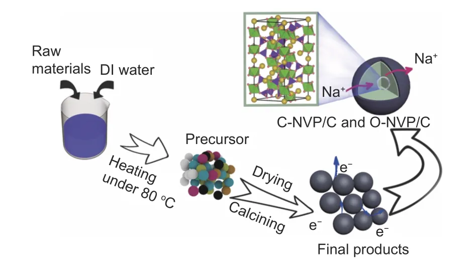
Fig. 1 Schematic of synthesis for NVP/C materials via sol-gel method.
2.3 Cell assembly and electrochemical measurements
The electrochemical performances of various NVP/C cathodes were carried out by 2016-type halfcells with the Na metal as anode material. To fabricate the cathode electrode, the slurry composed of 70%NVP/C products, 20% acetylene and 10% polyvinylidene fluoride with the N-methylpyrrolidone as the solvent was uniformly pasted onto a clean Al substrate. Then, it was vacuum dried at 120 °C overnight and punched into a circle shape. Besides, 1 mol L−1of NaClO4dissolved in EC/DEC+5% FEC solution was served as an electrolyte. The seperator was constituted by a commercial membrane (Celgard 2400). It should be noted that the whole fabricatd process was conducted in an airtight glove box filled with Ar. The cells were tested by a universal galvanostatic charge/discharge (GCD) method with a range of 2.3–4.1 V in a LAND CT2001 instrument. In addition,the kinetics properties of NVP were evaluated by cyclic voltammetry (CV) and electrochemical impedance spectroscopy (EIS), which were explored by an electrochemical workstation (IVIUMnSTAT). CV data were recorded in the voltage range of 2.3–4.1 V at various scan rates. EIS measurement was proceeded within the frequency scope of 10–100 MHz.
3 Results and discussion
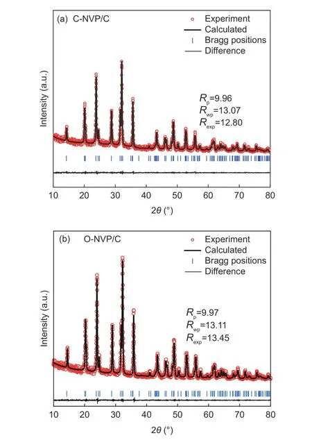
Fig. 2 Refined XRD patterns of (a) C-NVP/C and (b) O-NVP/C.
Fig. 2a presents the XRD patterns of both as-prepared samples with the similar diffraction peaks, coinciding with the typical R-3c group for NVP system.Moreover, no extra impurities are detected for both samples, indicating the high purity. To deeply investigate the lattice parameters, we conduct the Highscore software to complete the refinements. As revealed in Fig. 2b and c, the low R-values for the refined results suggest the high veracity and reliability.Moreover, the refined parameters are presented in Table 1. For C-NVP/C sample, the lattice parameters of a(b), c, V are 0.8716 nm, 2.182 nm, 1.435 38 nm3,respectively. And the same parameters values for ONVP/C composite are 0.8703 nm, 2.177 nm,1.428 02 nm3. According to the previous reports, there are three different ways for Na+transportation during the electrochemical process. Notably, the energy barrier for Na+migration in NVP bulk along c-axis is the lowest among all the routes. It can be speculated that Na+is favorable to transport along c-axis direction. As revealed in Table 1, obviously, C-NVP/C possesses a larger cell axial length and volume compared with ONVP/C. Accordingly, the enlarged c parameter promotes the movement of Na+effectively. Moreover, the enlarged crystal volume for C-NVP/C can further facilitate the Na+diffusion and stabilize the crystal structure effectively.
Fig. 3 shows the SEM images of both C-NVP/C and O-NVP/C samples, illustrating the aggregated particles with irregular shape. The agglomeration of sample is derived from the sintering reaction. Specifically, C-NVP/C composite reveals a smaller grain size compared with O-NVP/C, indicating the shortened pathway for Na+migration in C-NVP/C bulk. Furthermore, EDX mapping analysis is conducted to confirm the constituent elements. Obviously,different elements of Na, V, P and C are distributed homogeneously in the bulk of C-NVP/C active grain,demonstrating the carbon coating is successfully coated as design.
To deeply investigate the microstructure and lattice characteristics of C-NVP/C sample, TEM measurement is explored and the result is displayed in Fig. 4. Both of 2 samples possess agglomerated particles with irregular shape. The average value of particle size for C-NVP/C and O-NVP/C is 1 and 3 μm, respectively.
Furthermore, HRTEM images of C-NVP/C sample are revealed in Fig. 5 to investigate the detailed morphological information. As displayed in Fig. 5a, a thin carbon layer is observed surrounding the active grain, suggesting the successful coating of conductive carbon during the preparation process.This phenomenon coincides with the excess addition of carbon resources. Significantly, the uniformly covered amorphous carbon can induce an effective conductive framework for the accelerated electronic transportation, resulting in superior rate capability and cycling performance. Fig. 5b shows the HRTEM plot of C-NVP/C, presenting important information about the crystal properties. Clearly, distinct lattice fringes are observed with a cell spacing of 0.253 nm, agreeing well with the (214) plane in NVP system. The legible stripes for C-NVP/C indicate the great crystallinity and stable crystal construction, greatly improving the reversible de-intercalation of Na+.Moreover, FFT image for the lattice is revealed inside the figure, further proofing the favorable crystallization property. It is worth mentioning that a homogeneous carbon layer is covered onto the active particle with the thickness about 2 nm, providing a beneficial conductive framework for electronic transport.

Table 1 Refined cell parameters for C-NVP/C and O-NVP/C.
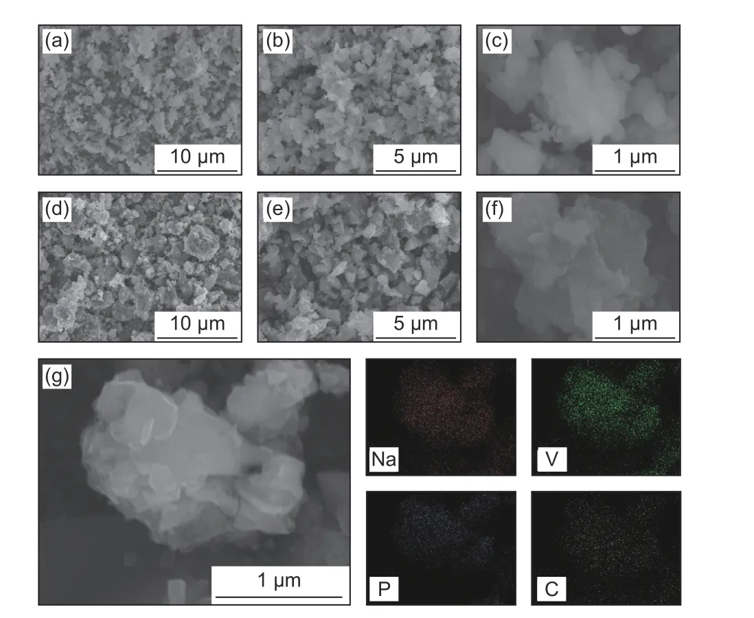
Fig. 3 SEM images of (a,b,c) C-NVP/C and (d,e,f) O-NVP/C samples;(g) EDX mapping image of C-NVP/C composite .
Fig. 6 reveals the HRTEM images of O-NVP/C.The O-NVP/C possesses agglomerated active grains with irregular morphology. Meanwhile, the amorphous carbon layers are observed around the particles.Fig. 6b presents the HRTEM image of O-NVP/C, suggesting a cell spacing of 0.361 nm, representing the lattice plane of (006) in NVP system. Notably, the lattice fringes of O-NVP/C are much vaguer than those of C-NVP/C, indicating the C-NVP/C possesses a better crystal structure. Moreover, the thickness of carbon layer for O-NVP/C is around 20 nm, which is much thicker than that of C-NVP/C. The thick carbon layer impedes the migration of Na+, leading to a poor ionic conductivity for O-NVP/C.
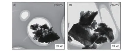
Fig. 4 TEM images of (a) C-NVP/C and (b) O-NVP/C.
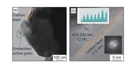
Fig. 5 (a) TEM image and (b) HRTEM image of C-NVP/C sample (insert graph is FFT result).
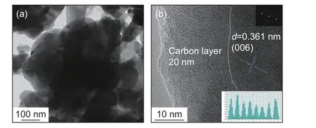
Fig. 6 (a) TEM image and (b) HRTEM image of O-NVP/C(insert graph is FFT result).
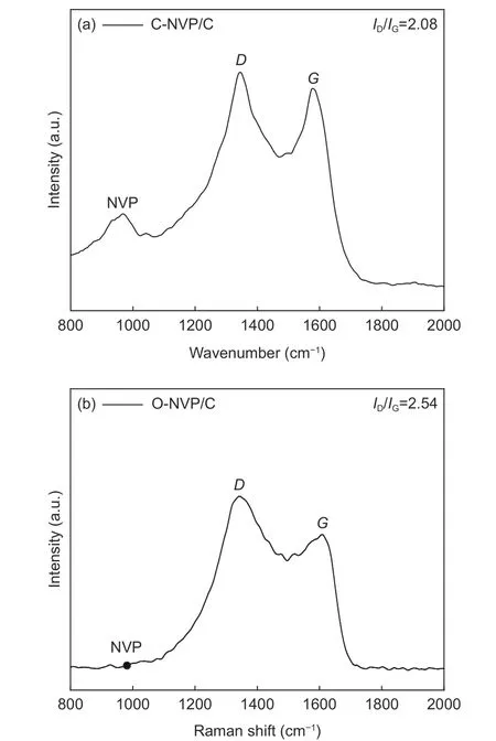
Fig. 7 Raman spectra of (a) C-NVP/C and (b) O-NVP/C.
Raman spectra are acquired to explore the turbostratic character of the carbon layer for C-NVP/C sample, whose range is 1 000-2 000 cm−1. As presented in Fig. 7a, we can find a slight peak at 980 cm−1,demonstrating the presence of Na3V2(PO4)3. Obviously, 2 distinct bands at 1 352 and 1 591 cm−1are appeared, which are ascribed to theDandGbands for disordered carbon. Specifically,Dband represents the long-range disorder property andGband behaves as the E2g vibrations of graphitic structure. Moreover,we can get the information about the property for the carbon material by calculating the ratio ofID/IG. As we can see from Fig. 7a, theID/IGratio for C-NVP/C composite is 2.08, demonstrating the carbon layer is composed of two modes of carbon phase. For comparison, we have carried out the Raman test of O-NVP/C sample to investigate the carbon property derived from the different carbon resources. As presented in Fig. 7b, the peak location is similar with the results of C-NVP/C. Moreover, theID/IGratio of O-NVP/C is 2.54, higher than that of C-NVP/C, demonstrating the C-NVP/C possesses much more graphitized carbon phase and therefore behaviors better electronic conductive property.
To explore the effects of carbon resources on the chemical valence of different elements, XPS measurement is conducted. Fig. 8a and b show the XPS survey spectra of both samples with a range of 100-1 350 eV. The typical peaks are similar for both samples, indicating that 4 kinds of elements are emerged. Characteristic peak representing Na1s appears at 1 071.19 and 1 071.35 eV for C-NVP/C and O-NVP/C[31,32]. Obviously, the peak shape is sharper and intensity is stronger for C-NVP/C, indicating the enhanced chemical stability of C-NVP/C . Moreover,for both samples, the V2p core level is fitted and divided into two peaks located at 523 and 516 eV, representing the V3+2p1/2 and V3+2p3/2 characteristic peak deconvolution. Furthermore, no redundant signals representing V4+/V5+are detected in these two composites, indicating that the original V5+has been successfully reduced to V3+during the carbothermal reduction[33–35]. Besides, the energy value of V2p for C-NVP/C is slightly smaller than that of O-NVP/C,suggesting C-NVP/C possesses a lower energy system to provide a more stable framework for migration of Na+[36–38].
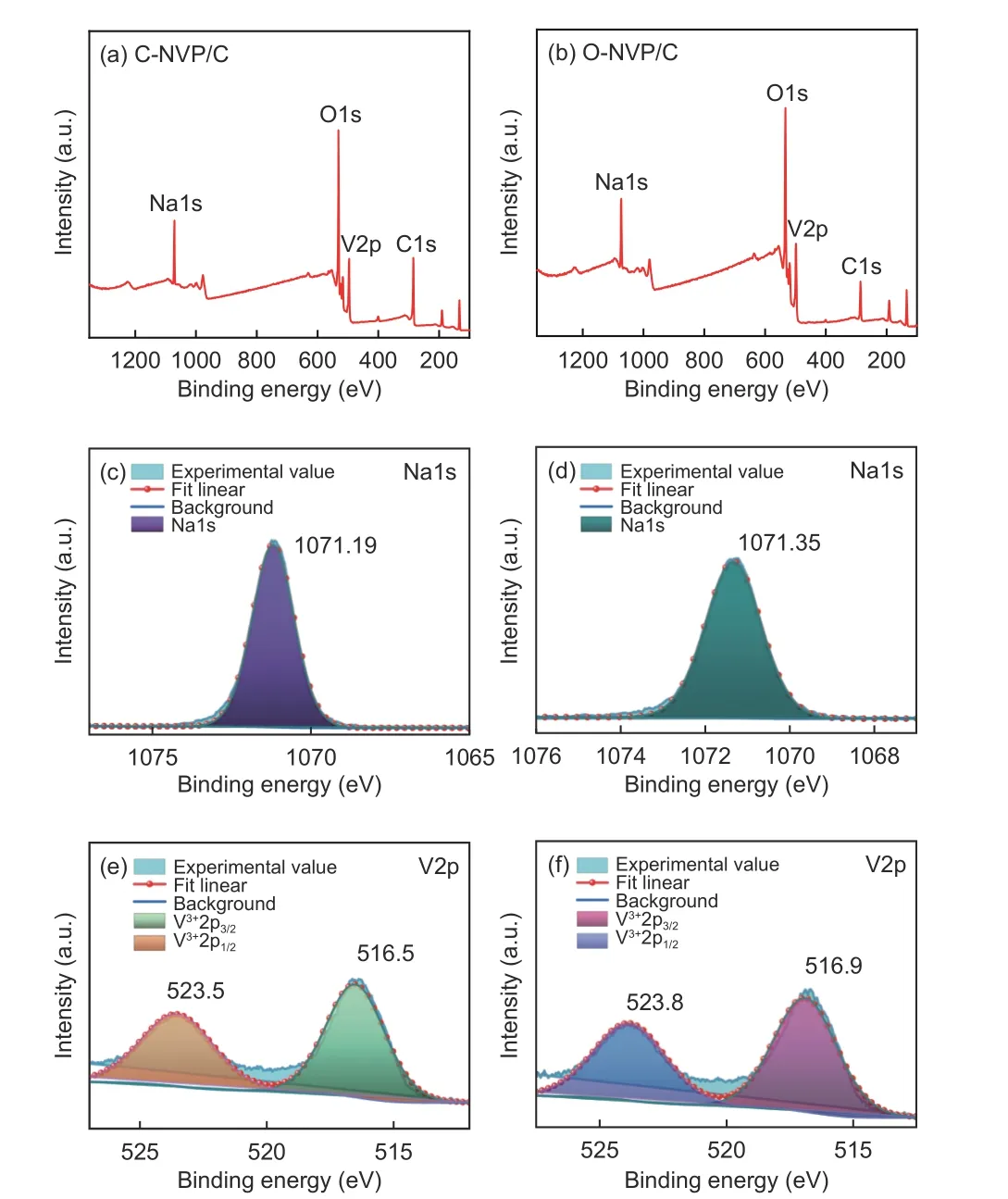
Fig. 8 XPS survey spectra of (a) C-NVP/C and (b) O-NVP/C ; Core levels of Na1s for (c) C-NVP/C and (d) O-NVP/C; Core levels of V2p for (e) CNVP/C and (f) O-NVP/C.
CV measurements are implemented in order to study the electrochemical behaviors of both electrodes. The tseting scope is 2.3-4.1 V with 0.1 mV s−1.As seen from Fig. 9a, both electrodes reveal one pair of peaks at 3.4 V, representing the reversible V3+/V4+reaction, which results in the rearrangement of structure from Na3V2(PO4)3to Na1V2(PO4)3. Significantly,the peak current of C-NVP/C is obviously larger than that of O-NVP/C, indicating C-NVP/C can release a larger reversible capacity during the electrochemical process. Moreover, the C-NVP/C electrode reveals a much lower polarization voltage compared with ONVP/C, suggesting it possesses a greater electrochemical reversibility during the charge/discharge procedures. Besides, no extra redox peaks are detected for both samples, coinciding well with the pure NVP phase shown in XRD patterns. For deep investigations of the kinetic characteristics, CV curves of both electrodes testes at a series of scan rates are displayed in Fig. 9b and d. With the increase of scan rate for CV measurement (0.1-5 mV s−1), the current value accordingly gets larger. Consequently, the polarization reaction of the battery is getting more severe. As a result,the oxidation and reduction peaks shift obviously when the scan rate increases. Notably, the polarization voltage obviously grows, leading to the augmented irreversibility. The sharp shape of peaks for CNVP/C electrode represents the reactive redox reaction of V3+/V4+. Meanwhile, we obtain the apparent diffusion coefficients of Na+(DNa+) for both cathodes during charge and discharge processes by Randles-Sevcik equation as shown below:
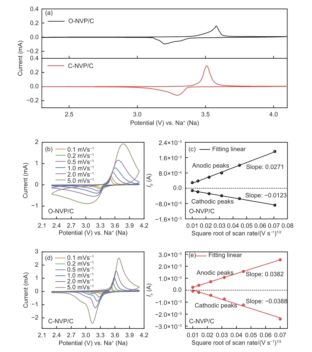
Fig. 9 (a) CV curves of both samples at 0.1 mV s−1; CV curves of (b) ONVP/C and (d) C-NVP/C at different scan rate from 0.1 to 5 mV s−1;Relationship between Ip and v1/2 of (c) O-NVP/C and (e) C-NVP/C.

The relationship betweenIpandν1/2for both electrodes is shown in Fig. 9c and e. Based on the fitting results, the slope and calculatedDNa+values can be obtained and the results are shown in Table 2. Obviously, the C-NVP/C presents the highest values of 5.02×10⁻¹¹and 5.36×10⁻¹¹cm2s−1for the desodiation and sodiation processes. This superior migration capability of Na+for C-NVP/C can be ascribed to the large crystal volume and small grain size, providing an expanded channel and shortened pathway for Na+transportation.
Moreover, the diffusion coefficient of Na+represents the migration capability of Na+throughout the active bulk and the interface between the grain and electrolyte. O-NVP/C possesses a thick and uneven carbon layer on the surface of active grain, leading to a serious obstruction for the Na+transportation. Therefore, the de-intercalation of Na+through the surface between the particle and electrolyte is hindered for ONVP/C. Consequently, it reveals an inferior diffusion coefficient of Na+during the electrochemical process.
EIS measurements for both electrodes charged to 3.4 V are carried out to explore the kinetic behaviors.As displayed in Fig. 10a, both samples reveal typical Nyquist plots, containing one semicircle and one incline line, which represent the the charge transfer resistance (Rct) and Warburg impedance (Zw). To obtain the quantized kinetic parameters, we fit the results according to an equivalent circuit model in Fig. 10a and Table 3. Obviously, C-NVP/C presents a much smallerRctvalue of 273.5 Ω compared with O-NVP/C, originated from the uniformly coated carbon layer and reduced particle size, resulting in a significantly improved charge transfer property. Moreover, a linear relationship betweenZreandω−1/2is shown in Fig. 10b,which is benificail to calculating the Na+diffusion coefficient (DNa+) by the following equations:

Table 2 Apparent diffusion coefficients of Na+ of both electrodes.


The calculated values ofDNa+are displayed in Table 3. Notably, C-NVP/C cathode behaves a high value of 3.69×10⁻¹³cm2s−1, which is one order of magnitude higher than that of O-NVP/C. The improved kinetic parameter agrees well with the results of CV measurement.
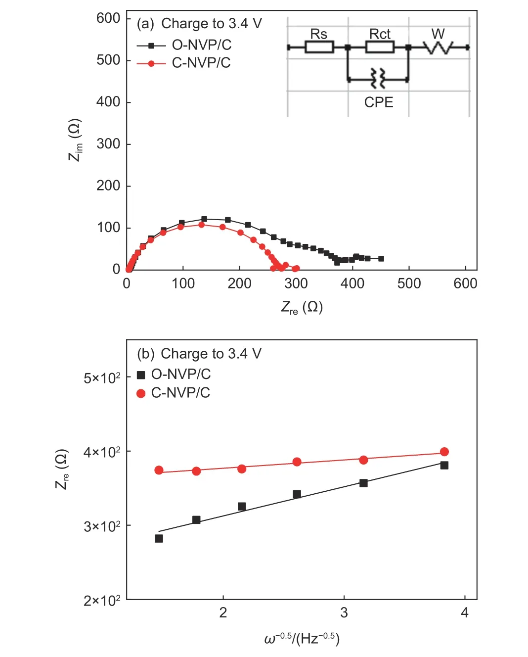
Fig. 10 (a) Nyquist plots of C-NVP/C and O-NVP/C measured at a charge state (insert: equivalent circuit model); (b) Relationship between Z’ and ω−0.5 in the low-frequency region.

Table 3 Fitted Rct, σ, DNa+ values for C-NVP/C and ONVP/C electrodes.
The GCD tests of both electrodes are investigated with the voltage range of 2.3-4.1 V. Fig. 11a displays the initial curves of both composites at 0.1 C, revealing that both electrodes can release a relatively high value of 112.3 mAh g−1, demonstrating the excellent capability of de-intercalation of Na+. Noteworthily, C-NVP/C reveals a slightly smaller polarization potential in contrast to O-NVP/C, agreeing well with the research of CV. As for the rate performance, CNVP/C cathode presents a better property. It delivers discharge capacities of 111.7, 94.6, 89.1, 85.8, 83.3 and 80.0 mAh g−1at various rate of 0.1, 1, 2, 3, 5 and 10 C. Moreover, the discharge value recovers to 110.4 mAh g−1when the rate goes back to 0.1 C. For O-NVP/C electrode, it behaves specific capacities of 109.5, 96.6, 91.1, 84.7, 79.8 and 72.6 mAh g−1at various rates. The performance at low rates is competitive.However, the sodium storage property is getting poorer when the rate increases to 5 C. Besides, the resumptive value at 0.1 C is also lower than that of CNVP/C. The excellent rate capability of C-NVP/C can be ascribed to its facilitated electronic conductivity.Moreover, the cyclic property of both samples are tested at 1 C for 200 cycles, as shown in Fig. 11c. The two original cycles are conducted at 0.1 C to activiate the cathode materials. Distinctively, there is no decay of the discharge capacity for C-NVP/C during the prolonged procedure. It can release a value of 99.1 mAh g−1at 1 C after 200 cycles. The corresponding retention reaches to nearly 100%, indicating the enhanced crystal structure framework. However, as for O-NVP/C, it shows 93.7 mAh g−1at 1stcycle and maintains about 76.1 mAh g−1after 200 cycles, suggesting a retention of 81.2%. Meanwhile, coulombic efficiency of C-NVP/C is labled in Fig. 11c, maintaining at 100% during the whole procedure, demonstrating the favorable reversibility for C-NVP/C electrode.Significantly, the remarkable enhancement in cycling stability of C-NVP/C is much more prominent at higher rates (Fig. 11d). It can still deliver high capacities of 90.0 and 89.1 mAh g−1at 1stcycle, keeping high discharge capacities of 83.4 and 79.8 mAh g−1after 200 cycles at 2 C and 5 C. The retention ratios are as high as 92.7% and 90.0%.
For different carbon precursors, the most influential impact for the composites is the property of coated carbon layers. The two organic acids are acting as not only reductive agents to achieve the redox reaction of V3+/V5+, but also the chelating agents to generate the amorphous carbon coatings in the sol-gel synthesis process. As a chelating agent, oxalic acid only can release two ligands of “―OOC―” and “―COO―”. As for citric acid system, three protons are ionized to form three “―COO―” coordination functional groups.The more ligands are released, the more homogeneous carbon layers will be formed. Consequently, citric acid is a better chelating agent due to the abundant ligands to accomplish the uniform coating.
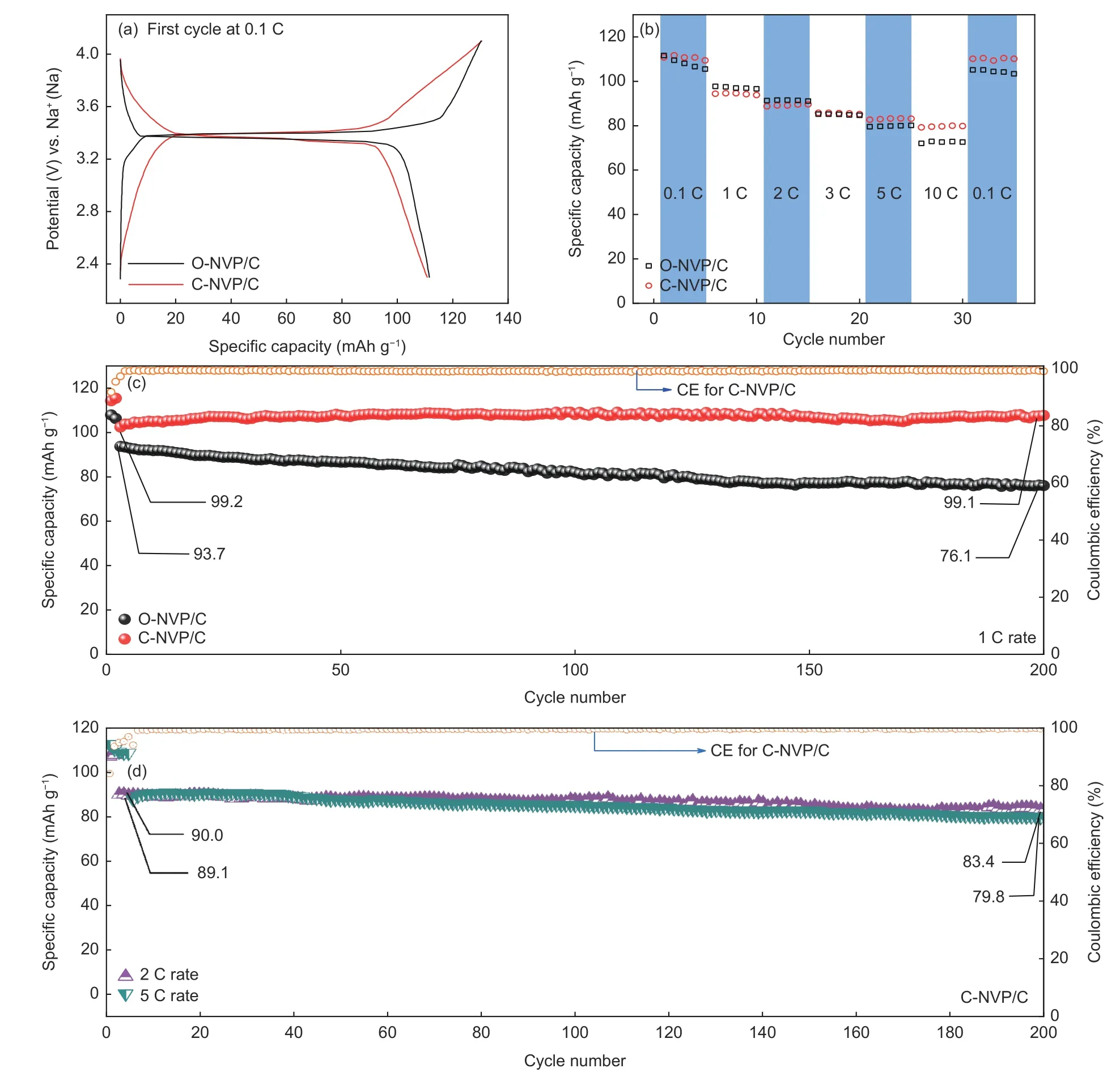
Fig. 11 (a) First cycle at 0.1 C for C-NVP/C and O-NVP/C cathodes. (b) Rate capability of both electrodes from 0.1 to 10 C.Cycling performance of both samples at (c) 2 C and (d) 5 C.
As revealed in TEM image, O-NVP/C displays a much thicker carbon layer with serious agglomeration.As comparison, the thin carbon coating of C-NVP/C indicates the uniform covering in the system. Consequently, for C-NVP/C system, the coated carbon layer can construct a beneficial conductive network for the accelerated electronic migration. Meanwhile,the thin carbon layers surrounding the active grain do not affect the de-intercalation of Na+through the surface between the particle and electrolyte, resulting in a distinctive ionic migration capability. Synthetically,C-NVP/C can release superior rate capability and cyclic performance.
4 Conclusion
In current work, the amorphous carbon layer coated NVP/C originated from citric acid and oxalic acid are successfully synthesized by a facile sol-gel route. The effects of different carbon sources on the crystal structure, morphological features and electrochemical performance are deeply investigated. It has been demonstrated that the optimized C-NVP/C possesses a larger interplanar spacing and a smaller grain size compared with O-NVP/C, resulting in the superior kinetic characteristics. Accordingly, the C-NVP/C electrode reveals an improved sodium storage property. It releases 112.3 mAh g−1capacity at 0.1 C.Moreover, the retention ratio is nearly 100% cycled at 1 C rate after 200 cycles. Distinct reversible capacities of 90.0 and 89.1 mAh g−1are acquired at 2 and 5 C rate, accompanied by high retention of 92.7% and 90.0% after 200 cycles. Such superior storage capability is derived from the improved ionic and electronic conductivity. This work provides a favorable approach for high-performance cathode system utilized in energy storage materials.
Acknowledgements
The present work is financially supported by Scientific and Technological Innovation Programs of Higher Education Institutions in Shanxi (STIP)(No.2019L0538), Major Science and Technology Projects of Shanxi Province (No.20181102018), Program for the Innovative Talents of Higher Education Institutions of Shanxi (PTIT) and Science Foundation of North University of China (XJJ201821). The authors also thanks Hengcong Qin from Shiyanjia Lab(www.shiyanjia.com) for the XRD and XPS analysis.
- 新型炭材料的其它文章
- Preparation of a porous carbon from Enteromorpha prolifera with excellent electrochemical properties
- High-surface-area porous carbons produced by the mild KOH activation of a chitosan hydrochar and their CO2 capture
- A DFT study of the effect of stacking on the quantum capacitance of bilayer graphene materials
- 基于碳化钽涂层改性碳基材料的研究进展
- Preparation of a N-P co-doped waste cotton fabric-based activated carbon for supercapacitor electrodes
- Two-dimensional layer materials for highly efficient molecular sensing based on surface-enhanced Raman scattering

