Fuel-optimal deorbit scheme of space debris using tethered space-tug based on pseudospectral method
Haiping RAO, Rui ZHONG, Pengjie LI
School of Astronautics, Beihang University, Beijing 100191, China
KEYWORDS Gauss pesudospectral;Model predictive controller;Fuel-optimal deorbit scheme;Space tethered tug;Space debris deorbit
Abstract This paper proposes a fuel-optimal deorbit scheme for space debris deorbit using tethered space tug. The scheme contains three stages named respectively as dragging, maintenance and swinging. In the first stage, the tug, propelled by continuous thrust, tows deorbit to a transfer orbit with a tether.Then in the second stage,the combination of the tug and the debris flies unpowered and uncontrolled to a swing point on the transfer orbit. Finally, in the third stage, the tug is propelled at the swing point and the rotation speed of the tethered system increases such that the debris obtains enough velocity increment. The trajectory optimization of the first stage is established considering the total fuel consumption of the three stages,whereas the dynamic model is simplified for computation efficiency. The solution to the optimal problem is obtained using a direct method based on Gauss pesudospectral discretization. Then a model predictive controller is designed to track the open-loop optimal reference trajectories, reducing the states’ deviations caused by model simplification and ignorance of perturbations. Furthermore, it is proved that the fuel-optimal swing point is the apogee of the transfer orbit. The paper analyzes the fuel consumption of a typical scenario and demonstrates effectiveness of the proposed deorbit scheme numerically.
1. Introduction
The clearance of space debris has attracted increasing attentions from major space agencies and academic communities all around the world.Among all possible space debris removal methods,the Tethered Space-Tug (TST) is one of the most promising options because of its advantages such as light weight, simple structure, and remote operation. It is necessary to optimize the deorbit fuel consumption due to economic reasons and limited capacity of the fuel tank. The fuel optimization of the TST, which is rarely reported in literature, is especially worth studying considering the coupling effect between the orbit motion and the tether libration. Nevertheless, it is difficult to obtain an analytic solution to the optimal control problem of the tether-towed deorbit. The difficulty is majorly caused by the highly nonlinear dynamics of the Space Tethered System (STS).
The dynamics and control of the STS have been studied extensively by forerunners, such as Misra,who proposed a very general dynamic model for the tether system in 1980.Their model considers not only the tether distributed mass and the tether libration,but also the offset of the tether attaching points on the end-satellites. Qi et al.proposed the Coulomb tether double-pyramid satellite formation, which includes a cluster of charged satellites repelling each other by Debye-shielded Coulomb forces and two counterweights connecting to each satellite via elastic massless tethers. The TST is regarded as a major application of the space tethers in recent decades.In 2001,the European Space Agency(ESA)proposed the Robotic Geostationary Orbit Restorer(ROGER)project.The control strategy suggested by this project can effectively suppress the tether swing during the deorbit process of the STS. Numerous control methods have been designed afterwards, in order to reduce the tether libration or to stabilize the attitude motion of the tethered end-body. Qi et al.proposed the double-tethered space-tug concept and a control scheme which is successful in maintaining a constant attitude of debris and a constant length of one tether, and the amplitude of the swing of the system attenuates with time. Zhang et al.designed a control law which would suppress the initially spinning debris and tug,as well as the oscillation of the tether,by regulating the tether length and the tether offset in a singletethered space-tug system. For the libration control of the tether, Sun and Zhangpresented a switched low-propulsion force control method using only two constant-thrust modes and Williamsproposed a new control approach for stabilizing electrodynamic tethers around their periodic solutions without a priori knowledge of the periodic solution. Wen et al.presented a tension control law to stabilize the motions of a Tethered Space-Tug system during its deorbiting process by regulating the tension in the tether. Zhao et al.proposed a thrust control method of tethered satellite with a short constant tether in orbital maneuvering. In this method, the thrust acceleration imposed on the base satellite can be adjusted to avoid the slackness of tether and damp out the librational angles. Shi et al.designed a new tension control law to suppress the libration of tethered multi-satellites in a desired periodic motion by regulating tether length without thrust.For the attitude dynamics of the tethered end-body,Wang et al.proposed a novel way to control the attitude of debris towed with off-centered capture using only tether and Yang et al.proposed a hierarchical tether architecture to stabilize the debris with a main tether from the tug branched into multiple subtethers attached to the edges of the debris. Sabey and Tragesserdesigned a Linear Quadratic Regulator (LQR)paired with a reduced-order closed loop to control the attitude of each end-mass individually using Reaction Wheel Assemblies (RWAs), assuming measured angular rates from gyroscopes on the end-masses and tether. Peters et al.proposed that the selection of the appropriate tether material while using simple controllers can reduce the effort needed for tethered deorbiting and can safely control the attitude of the debris/chaser connected with a tether, without the danger of a collision.Zhang et al.addresses the problem of position and attitude control of a tethered space-tug system with only tether tension available for the target.Based on Takagi-Sugeno fuzzy technology, a guaranteed cost guidance and control law is obtained by solving a set of linear matrix inequalities. Kang et al.characterizes the dynamics and de-spin control of a massive target by a tethered space tug for the safety and feasibility of spinning large target removal. Kang and Zhualso investigated the de-spin control problem of giant asteroids by deploying small tethered spacecraft in the post-capture operation of asteroid redirection or space debris removal.Two simple and novel feedback control laws are developed based on dynamic characteristics of the tethered asteroidspacecraft system.
In terms of the deorbit optimization,Liu et al.proposed a scheme for removing abandoned satellites orbiting in a geosynchronous orbit by the TST technique.His proposal consists of four phases: Acceleration, equilibrium, rotation, and return.Simulation shows that the scheme is feasible and can save fuel consumption during the whole process. Zhong and Zhudesigned a piecewise two-phased optimal control scheme for fast nanosatellite deorbit by a short electrodynamic tether.The authors increased the deorbit efficiency sharply without losing the boundedness of the tether libration motion., and then they proposed a more applicable control scheme using current on-off regulations.Wen et al.presented an output feedback control law of electric current for achieving a fast and stable deorbit of an electrodynamic tether system. The proposed controller was designed on a basis of the Model Predictive Control (MPC) method to optimize the deorbiting performance while accounting for the system constraints and nonlinear dynamics. Meng et al.proposed a space tethered towing method, which includes orbit optimization and tether heading stabilization. Chu et al.presented optimal commands based multi-stage drag de-orbit design for a tethered system during large space debris removal.
In recent years,direct methods have been adopted widely to solve complicated optimization problems numerically. As one of the direct methods, the pseudospectral method has been applied successfully to a large number of theoretical and engineering challenges,such as trajectory planning for Unmanned Aerial Vehicles(UAVs),missile guidance,trajectory optimization of robotic arms, stabilization of inverted pendulums,orbit maneuver of spacecraft,and ascent guidance of the orbiter.The pseudospectral method has the merits of fast convergence and high accuracy, thus it has become the most effective tool for solving optimal control and trajectory optimization problems.
The pseudospectral method usually obtains the optimal reference trajectory through a simplified model.It is necessary to design a controller to track the reference trajectory.The model predictive controller is one of the most popular trajectory tracking controller. The feature of MPC is its ability to compensate model uncertainties and external disturbances while maintaining robustness. Manzoor et al.proposed an offsetfree MPC based trajectory tracking control of a DFUAV under various uncertainties and external disturbances. Cai et al.proposes a Virtual Target Guidance (VTG)-based distributed Model Predictive Control (MPC) scheme for formation control of multiple Unmanned Aerial Vehicles (UAVs).
Motivated by above researches,this article proposes a fueloptimal deorbit scheme for the debris removal by a TST. The scheme contains three stages, which are named as dragging,maintenance and swinging, respectively. The combination of the tug and the debris is accelerated by a continuous thrust in the first stage,and then in the second stage,the tethered system flies freely after the propulsion ceases until reaching a swing point.In the final stage,the rotation of the combination accelerates and the tether is cut off, ensuring that the debris enters a near circular graveyard orbit with the radius being 350 km higher than GEO altitude. The difference between the space tug in this paper and the spinning tether systems is that the tethered system is dragged to the designed transfer orbit at the beginning. The spinning systems requires multiple captures and swings to transfer the debris to the graveyard orbit.It will increase the risk of arrest and the difficulty of control. Unlike existed literature about the same topic, the fuel optimization of the whole deorbit process is considered. Trajectory optimization of the first stage is solved by defining a cost function of the total impulse required. Moreover, for safety reasons, the tether length of a typical TST is relatively short compared to other application of the STS. To avoid the difficulty of maintaining local horizontal configuration due to the small gravity gradient, the combination is designed to rotate and the tether is stretched naturally during the free fly phase.
The main contents of the paper are the following. In Section 2, the paper firstly establishes the dynamic model of the STS in the general case,and then simplifies the model with planar motion assumption to alleviate the challenge of the fuel optimization. In Section 3, the three-stage deorbit scheme is designed in detail, with the optimal transfer orbit and swing point determined. In Section 4, trajectory optimization problem of the first stage is given.A direct method based on Gauss pseudospectra discretization is adopted to calculate a reference optimal trajectory for the simplified dynamic model. Then a model predictive controller is designed for the general dynamic model,ensuring that the deviation from the optimal trajectory is minimized.Numerical simulation and discussion of a typical case using the proposed scheme is given in Section 5,and some useful conclusive points are presented in Section 6.
2. Equations of motion
2.1. Dynamic formulation of the STS
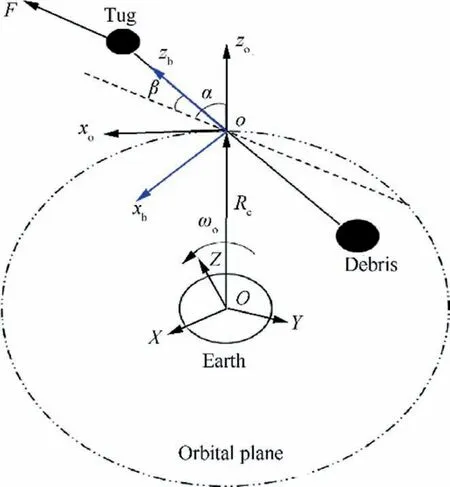
Fig. 1 Space tug and space debris connected via a tether.
The STS under investigation, containing an active space tug,a passive debris, and a rigid tether connecting them, as shown in Fig. 1, is modeled based on the dumbbell assumption. The space tug and the debris are treated as point mass mand mrespectively. The tether length is assumed constant and the mass of the tether is m. Namely,the STS’s Center of Mass (CM) is located along the tether.The STS is initially running in a Geosynchronous Orbit(GEO) and its tether length is assumed less than one kilometer. Due to the large ratio of the orbital size over the tether length, the difference between the STS’s CM and the center of gravity is ignored. Therefore, the motion of the STS can be decomposed into three-dimensional orbital motion of the STS’s CM and two-dimensional libration motion of the tether.


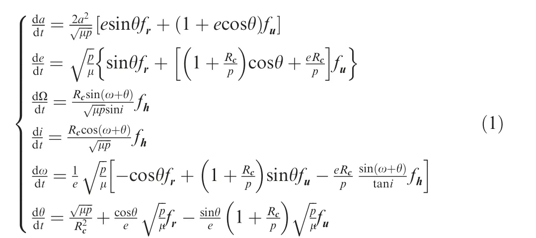
Based on above definitions, one can obtain the equations of orbital dynamic motion written in the form of Gaussian perturbation equationsand the equations of tether libration motion via Lagrange’s equations.The Gauss perturbation equations of six independent orbital elements, semi-major axis a, eccentricity e, right ascension of ascending node Ω,inclination i, argument of perigee ω, true anomaly θ are given as
The equations of tether libration motion of generalized coordinates, tether length l, in-plane angle α and out-ofplane angle β are given as:
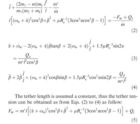
The components of perturbative accelerations, f, fand fare defined in the orbital coordinate frame oxyz, and their expression can be found in Ref.34. The total mass of the STS, m is equal to m=m+m+ m. The equivalent mass mis equal to m=(m+0.5m)(m+0.5m)/m-m/6, and mis equal to m=(m+m)mm. Q,Qand Qare the corresponding generalized forces of the generalized coordinates α,β and l respectively. The above generalized forces,obtained using virtual work principle,considers the perturbative effects of the propulsion force on the tug,Earth oblateness perturbation Jand lunisolar perturbations in the study. Their expressions can be found in Ref. 34.
2.2. Planar assumption for optimal trajectory solution
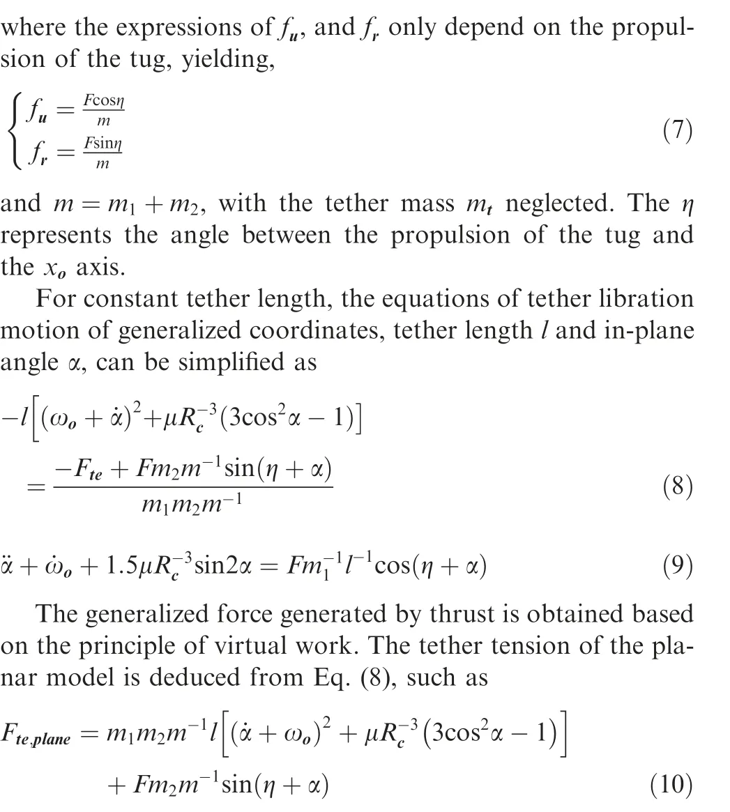
The out-of-planar motion lacks corresponding perturbances and the out-of-planar motion has less disturbance to in-plane motion.In order to reduce the scale of the optimal deorbit trajectory solution of the STS and improve calculation efficiency in the first stage,the dynamic model is simplified based on planar assumption. That is, only two-dimensional orbital motion of the STS’s CM and one-dimensional libration motion of the tether in the orbital plane are considered in the state and control trajectories optimization. No propulsion force out of the orbital plane is exerted on the tug,and its direction in the orbital plane is defined by an angle η deviated from the xaxis.The Earth’s oblateness and the lunisolar perturbations are ignored in the simplified model,i.e.,no perturbation forces are considered except the Earth’s spherical gravitational attraction and the continuously varying propulsion force acting on the tug.Moreover, the tether mass is ignored due to the limited value.
Theequationsoftheplanarorbitaldynamicmotioncanbesimplified form Eq.(1).The resulting differential equations of semimajor axis a,eccentricity e,true anomaly θ and given as follows

3. Fuel-optimal deorbit scheme design
3.1. Problem statement
The target of the fuel-optimal deorbit scheme is to transfer the space debris to graveyard orbit safely with minimal fuel consumption of the tug.There are three major risks under concern for the TST based debris removal application, namely tether slackness, tether winding with the tug and the debris, and collision between the tug and debris during the orbital transfer process. In addition, according to the GEO debris disposal advice of the Inter-Agency Space Debris Coordination Committee (IADC),the perigee radius of the graveyard orbit is 300 km higher than the GEO altitude. In this paper, a TST is assumed to remove debris initially running in a GEO and the target orbit is determined as a near circular graveyard orbit with the radius being 350 km higher than that of GEO.
3.2. Design process
The optimal deorbit scheme with minimum fuel consumption can be divided into three stages,namely dragging,maintenance and swinging,as shown in Fig.2.The optimization target is to reduce the total fuel consumption of the three stages.
In the first stage,the TST maneuvers to a transfer orbit by the propulsive force and the debris is towed to the designed transfer orbit together with the TST. This study assumes that both the magnitude and the orientation of the thrust can be adjusted.The optimal state trajectories of the STS in the first stage are derived by solving a fuel-optimal deorbit problem based on the simplified model.The fuel consumption of the whole deorbit process,rather than the first stage,is taken as the cost function.The possibility of obtaining total fuel consumption in this stage will be discussed later. Due to the model simplifications and ignorance of the major environmental perturbations, a closed loop controller is required. The model predictive control method is applied to suppress the state deviation from the derived optimal trajectories.When the STS reaches the desired transfer orbit,it enters the second stage,maintenance.
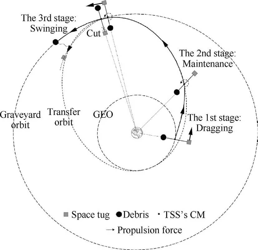
Fig. 2 Three phases of TSS deorbit.
In the second stage,the thruster of the tug is turned off and the STS orbits on the designed transfer orbit unpowered until reaching the swing location. The transfer orbit and the swing point have to be determined according to the fuel consumption, and the detailed design procedure will be given later. In order to prevent tether slackness and collision between the tug and debris during the second stage, the tether of the STS has to be stretched. Considering that the tether length is relatively small for a TST mission,local vertical stabilization relying on the limited gravitational gradient is not a good choice.Moreover, during the dragging stage, the STS is close to horizontal configuration to better utilize the thrust for acceleration, which means an orbit maneuver is required between the first stage and the second stage if a local vertical configuration is adopted. Therefore, in this paper, the STS is allowed to rotate with an in-plane angular velocity during the second stage, and the tether is naturally stretched. There is no strict constraint on the rotational rate, saving the control effort and the fuel consumption for the stage transformation. However, bounded tether librational motion is required at the end of the dragging stage,thus to ensure a safe rotational rate in the second stage.
In the third stage,the thruster of the tug is turned on at the swing point for a short time. The tug accelerates in the orbit plane, causing a rotation acceleration until the angular rate of the STS reaches the desired value. Due to the slow orbit motion of the STS, it is further assumed that the swinging stage starts when the tether pitch angle equals to 0 degree.On the other hand, the swinging stages ends and the tether is cut off when the STS becomes upside down with debris above,i.e.,the tether pitch angles becomes 180 degrees.Then the debris gets enough velocity increment through momentum exchange and enters a near circular graveyard orbit with the radius being 350 km higher than GEO altitude.
One can concludes from above description of the deorbit process that the total fuel consumption equals to the summation of those in the first stage and the third stage. The second stage is an unpowered and uncontrolled stage, so the fuel required for the third stage depends directly on the final states of the powered stage, the first stage. This makes it possible to choose the total fuel consumption as the cost function in determining the trajectory of the dragging stage.
3.3. Design transfer orbit and swing location
This section discusses the optimal design of the transfer orbit and swing point in the second stage. The purpose is to reduce the fuel consumption of the whole deorbit process.
Two conclusions of the optimal transfer orbit and swing point are given below.
(A) All orbits with apogee 350 km higher than GEO altitude can be candidates of the optimal transfer orbit.
(B) The optimal swing point is located at the apogee of the optimal transfer orbit.
Conclusion(A)is directly following the mission target,i.e.,transferring the debris to a near circular graveyard orbit with the radius being 350 km larger than that of GEO. The swinging stage provides a single velocity increment to the debris,and the debris is impossible to enter a new orbit with perigee radius larger than the former apogee radius with single impulse maneuver. Thus, the optimal transfer orbit must be an orbit with apogee 350 km no less than GEO altitude. For a candidate of optimal transfer orbit, one can easily concludes that the swinging point can be any point with radius larger than the designed graveyard orbit.
As shown in Fig. 3,r,r, and rdenote the radius of the GEO orbit, the apogee of the transfer orbit, and the perigee of the graveyard orbit respectively. The object in arc ACE of transfer orbit can reach desired graveyard orbit after single impulse. Supposing point B is the swing point and the swing time is negligible, point B is both on the transfer orbit and on the graveyard orbit after the swing.One can obtain the following equation,

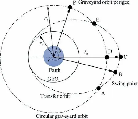
Fig. 3 Schematic diagram of selecting the position of the swing point.
where aand eare the semi-major axis and eccentricity of the transfer orbit.Based on the above equation,the orbital radius and the velocity of point B before swing can be obtained as follow,
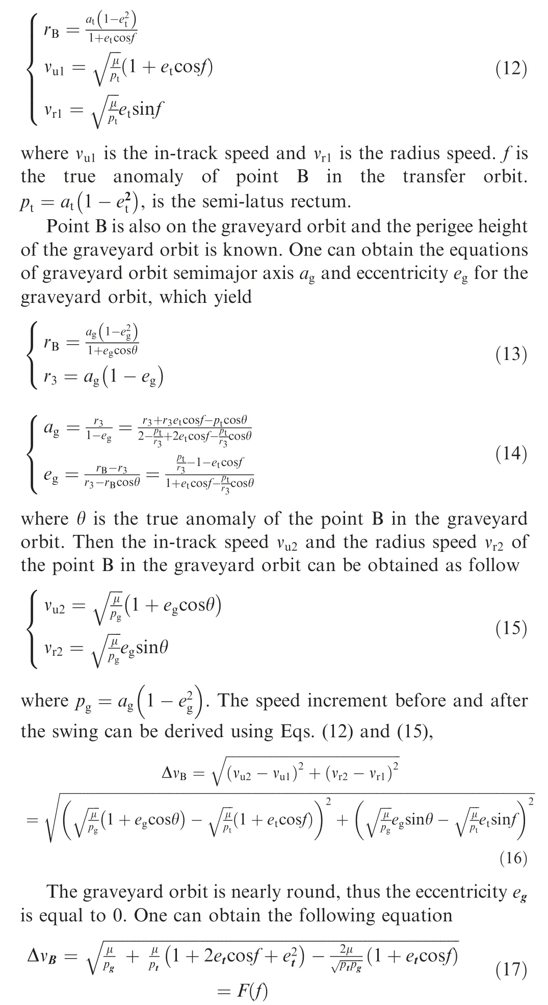
The required speed increment of debris is a function of the true anomalies f.The design of the swing point is to reduce Δνin Eq. (16), i.e., finding the minimum of F(f ). Analytical analysis shows that Δνhas a minimum value when f=π, disregarding the sizes of the transfer orbit and the graveyard orbit. The minimum condition indicates that point B is the apogee of the transfer orbit. Thus, conclusion (B) is proved,i.e.,the optimal swing point should be the apogee of the transfer orbit.
Given the perigee height of the transfer orbit equaling to the GEO altitude, higher apogee height means larger semimajor axis and also larger orbit energy.To reduce the fuel consumption in the dragging stage,the apogee height of the transfer orbit should be as small as possible. Therefore, the apogee height of the transfer orbit is chosen as 350 km higher than GEO altitude according to conclusion(A).On the other hand,the fuel consumption in the swinging stage depends not only on the transfer orbit, but also on the tether rotational rate in the second stage.The total fuel consumption minimization will be shown in the next section.
4. Optimal trajectory and tracking control of the STS in first stage
4.1.Open-loop optimal trajectory for the total fuel minimization
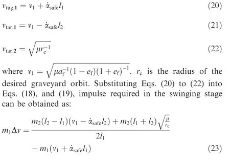
As mentioned in Section 3,part B,the fuel consumption in the swinging stage depends on the final state of the dragging stage,as the maintenance stage is unpowered.The next step is to construct an optimal control problem to solve the optimal trajectory of the STS in the first stage, while optimizing the fuel consumption of the whole deorbit process of three stages.According to the deorbit scheme proposed in Section 3, the fuel consumption of the whole deorbit process can be determined by the total impulse required during the first stage and the third stage. As for the first stage with continuous thrust, the impulse is simply the integral of thrust over time.To obtain the impulse required in the third stage,it is assumed that the impulse of the short-term thrust causes an equivalent momentum increment of the tug before the swing,and the slow orbit motion of the STS during the swing can be ignored.Then, according to the conservation of both the momentum and the angular momentum, one can obtain the following equations for the STS before the swing and after the swing:

where νand νare the in-track speeds of the tug before and after the swinging respectively. νand νare the in-track speeds of the debris before and after the swinging respectively.Δν is the speed increment of the tug obtained from the thruster in the swinging stage. land lare the distances from the tug and the debris respectively to the CM of the STS,respectively.Above scalar equations,Eqs.(19)and(20),are deduced by projecting corresponding velocities into the orbit frame.Moreover,denoting ˙αas the safe in-plane angular rate of the STS in the second stage.One can obtain the following equations:
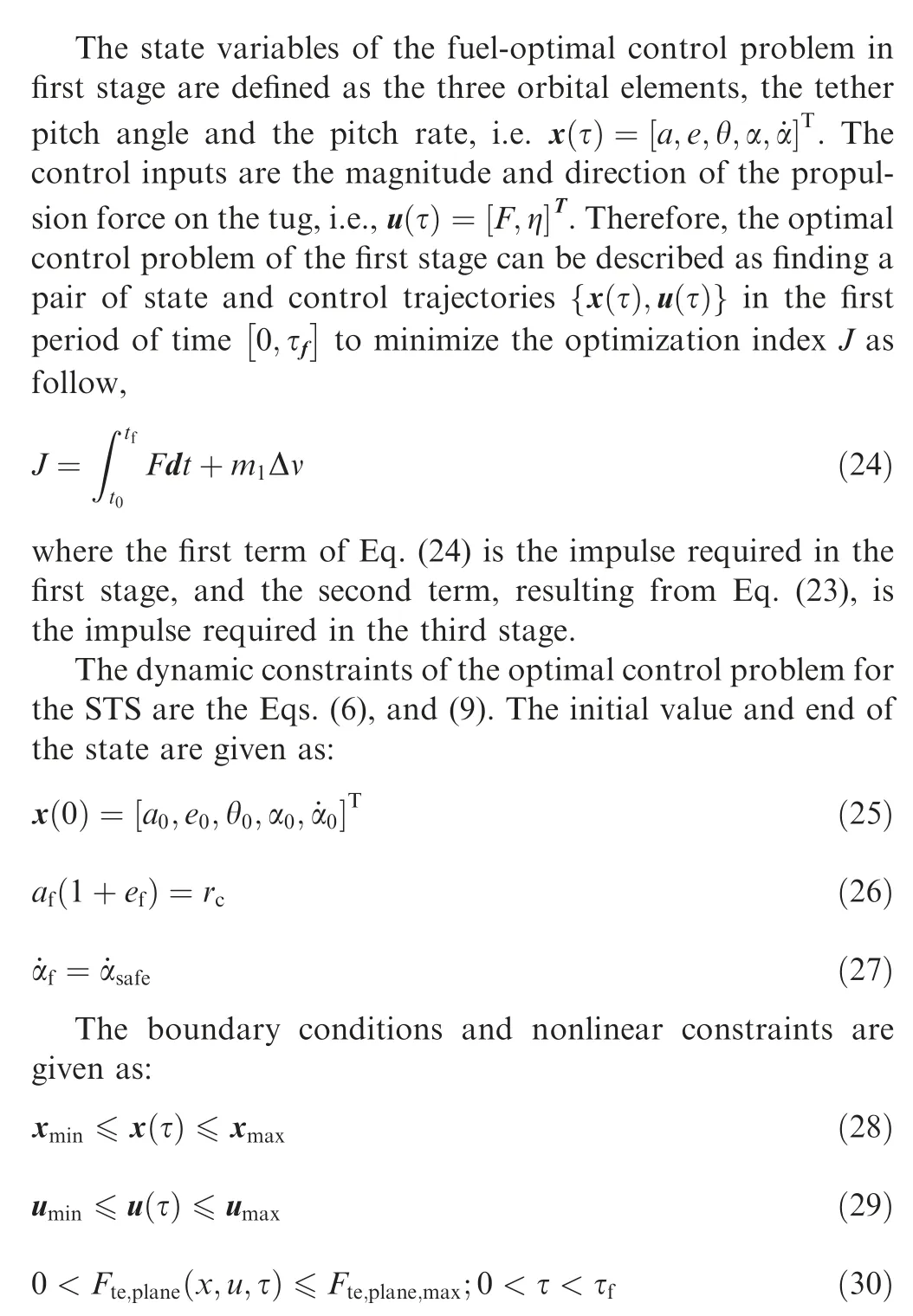
The above fuel-optimal control problem, i.e., minimization of Eq.(24)subjected to Eqs.(6),(9),and(25)to(30),is solved using the optimization solution toolbox GPOPSin MATLAB software, which gives the optimal fuel trajectories of the state variables and control inputs in the dragging stage.
4.2. Close-loop trajectory tracking based on model predictive control
Due to the simplification of the model and the existence of environmental disturbances, the open-loop optimal control trajectory obtained in Section 4, Part A is not accurate. Directly application to the control of the STS in the first stage does not reach the desired transfer orbit. Therefore, a model predictive controller is applied to eliminate system state deviations.More accurate system model, as shown in Eqs. (1), (3), and (4) is adopted for the close-loop control, and environmental perturbations are considered. The model predictive control method is designed based on the optimal feedback control method.The optimization index at each sampling moment k is given as:
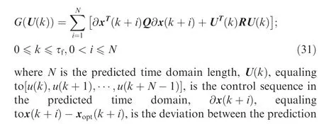
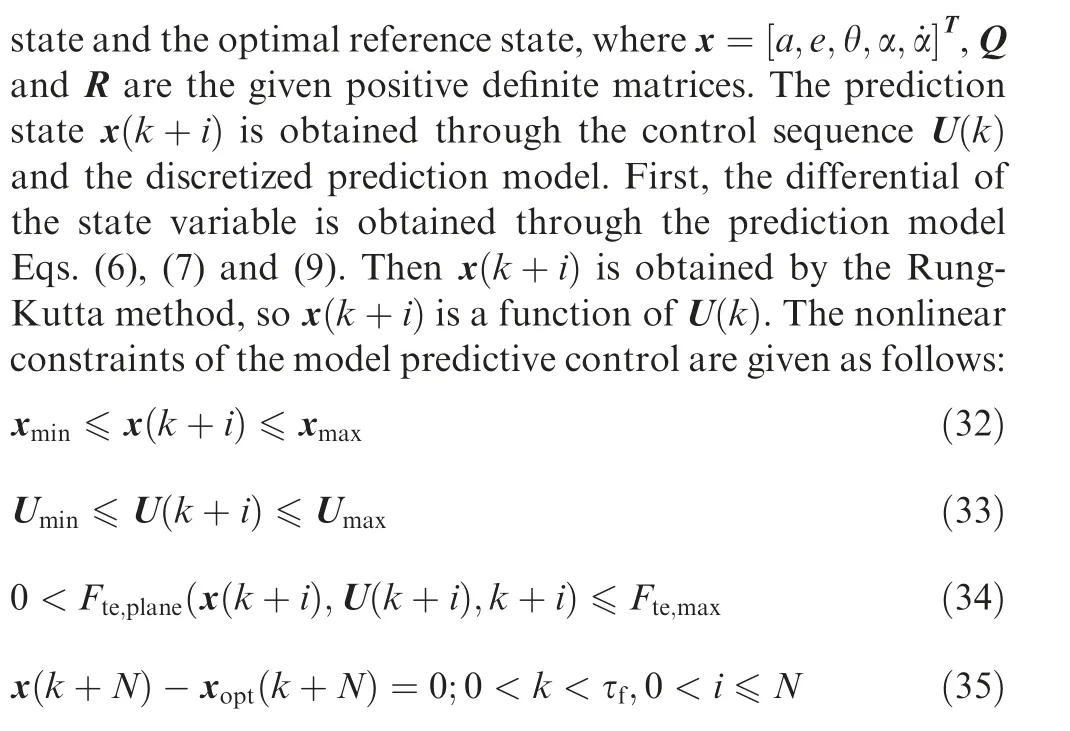
The model predictive controller solves a nonlinear programming problem at each sampling time, obtains feedback control U(k ),and then applies the first term u(k )to the system.The model predictive controller can track optimal state trajectory obtained by the pseudospectral method.Eqs.(32)and(34)restrict the tether pitch angle, pitch rate, and tether tension to avoid the three major risks of deorbit.Eq.(33)is the restriction of control inputs, and Eq. (35) guarantees the stability of the model predictive controller. Stability analysis of the proposed model predictive control can be found in 33.
5. Result and discussion
This section presents the simulation results of a typical case.The proposed deorbit scheme is applied to a STS consisting of the tug, the towed debris and the tether, while the system parameters are listed in Table 1. The STS is initially runningin the GEO orbit,with the tether stabilized along the local vertical direction.
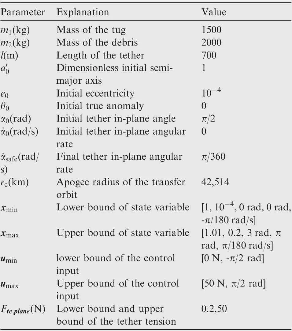
Table 1 System parameters and optimal trajectory solving parameters.
5.1. Open-loop optimal trajectory in the first stage
For better stating the simulation work, the lower and upper bounds of the state variables and control inputs for the optimization are also given in Table 1. The tether tension is set between 0.2 and 50 N in the dragging stage to avoid tether slackness or breaking. The STS is designed to rotate in the maintenance stage, because the gravitational gradient is too small to maintain a local vertical configuration for the STS(see Section 3.2). The STS rotates without control in the second stage,so the final angular rate of the STS in the first stage is set to be 5 revolution per hour for safety. The rotational speed is expected to change little during the second stage due to limited perturbative torques,and the tether will be naturally stretched for a rotational STS. Thus, there is no need to constraint the tether tension during the second stage. Moreover,dimensionless semi-major axis (a=a/a) is used to avoid numerical singularity in the optimization and the constant a=42164×10km is defined.
The optimal trajectories of the first stage are shown in Figs. 4 to 8. The trajectories are solved by the optimization procedure presented in Section 4.1.The STS reaches the transfer orbit at the end of the dragging stage, and the terminal rotational rate is equal to the desired safe value, π/360 rad/s,for the following stage(see Fig.5). The transfer orbit is determined by the terminal orbit parameters of the first stage,where the semi-major axis and the eccentricity of the transfer orbit is a=42337.45km and e=0.004170 respectively.
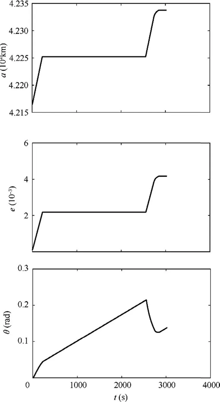
Fig. 4 Optimal trajectory of semi-major axis, eccentricity, and true anomalye.
More specifically, Fig. 4 shows the variation of the orbital parameters during the first stage. It is found that most of the time both the semi-major axis and eccentricity of the STS do not change much. But during the period [0 200 s] and [2500 s 2800 s],i.e.,the beginning and the end of the stage,the two orbit parameters increased rapidly. It can be seen in Fig. 7 that the apogee radius of the orbit reaches 42514 km, equaling to the desired radius of the graveyard orbit.Fig.5 gives the variation of the tether in-plane angle and angular rate.During the dragging stage,the tether in-plane angle is firstly reduced to 0,which means the STS changes to the local horizontal configuration for better acceleration,and then the tether swings back to generate a safe angular rate.The magnitude and the direction of the thrust is shown in Fig.6.It is seen that the thrust is well restricted to the range from 0 to 50 N,and the thrust mode is similar to a twoimpulse orbit transfer. It is noted that the thrust is not always along the horizontal direction, which helps to generate the desired tether libration motion. Propelled by a continuous thrust starting from the GEO, the apogee radius of the orbit increases sharply, whereas the perigee radius does not, as seen in Fig. 7. That suggests the necessity of swinging stage. One major concern is the tether tension during the dragging phase,which can be estimated using Eq.(11).It is found in Fig.8 that the tether tension is maintained within designed range,[0.2,50]N,preventing tether from slackness and breaking.
The overall impulse cost is calculated as J=2.8679×10kg·m/s,which consists of the impulse in the dragging stage and the swinging stage. The required impulse in the third stage can be calculated directly after the trajectory of the first stage determined. Following Eq. (25), the impulse cost for the swinging mΔν=0.6603×10kg·m/s. Thus, the required impulse for the dragging is 2.2076×10kg·m/s.For comparison, the impulse cost of a Hohmann transfer for a spacecraft with the same mass is calculated as 4.4388×10kg·m/s. It can be concluded that the impulse cost of the proposed optimal scheme is only 0.646 times that required by the Hohmann transfer.
5.2. Close-loop trajectory under model predictive controller
Considering the planar motion simplification used for the dynamic model to solve the optimal control problem, and the ignorance of existing perturbations such as the earth’s oblateness and the lunisolar gravitational attraction,the model predictive control method is applied to track the optimal reference trajectories in the first stage. The close-loop trajectories under controller presented in Section 4.2 are given in Figs. 9 to 12.
The spatial dynamic model of the STS as given in Eqs. (1)to (6) is adopted in the close-loop simulation, tether mass is also included for improving model accuracy. Additional system parameters can be found in Table 2, while other parameters are the kept unchanged as those in Table 1. Meanwhile,Table 3 gives the parameters of the model predictive controller.
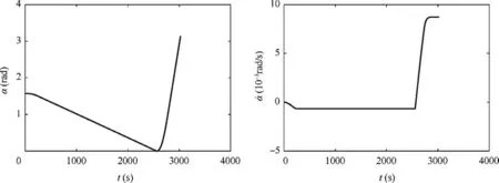
Fig. 5 Optimal trajectory of tether in-plane angle and angular rate.
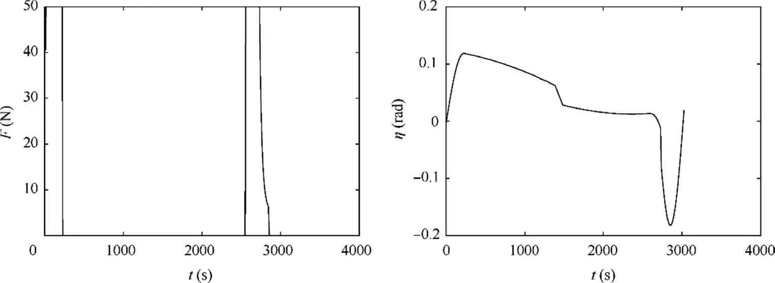
Fig.6 Optimal trajectory of magnitude and direction of thrust.
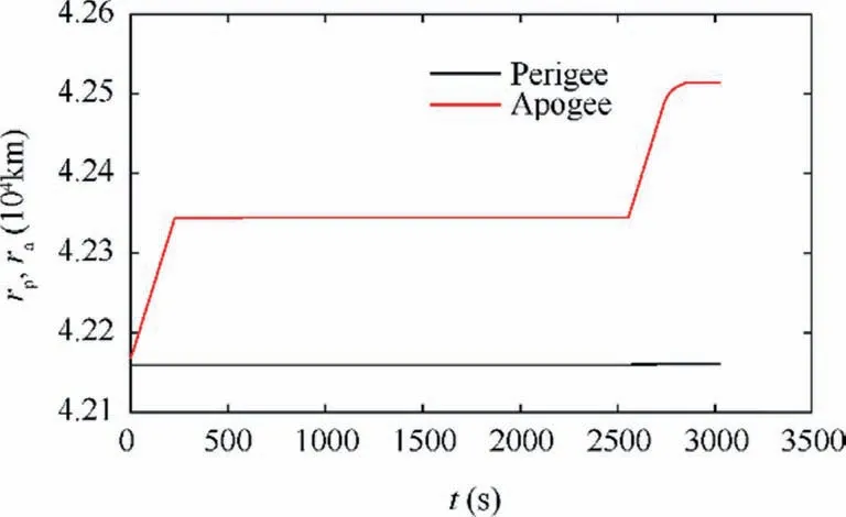
Fig. 7 Optimal trajectory of perigee and apogee radius.
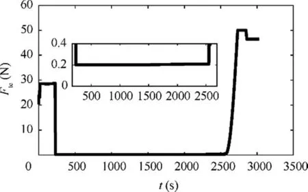
Fig. 8 Optimal trajectory of tether tension.
For comparison, the optimal trajectories are also shown in the Figs. 9-12, while some of system states do not have corresponding optimal trajectories due to the model simplification in the open-loop solving process.Figs.9 and 10 show the time history of the STS’s orbit motion and libration motion respectively. It can be seen that the proposed model predictive controller eliminates the state deviations and realizes the tracking of the optimal trajectories. The terminal semi-major axis and eccentricity of the STS are almost the same as those calculated from open-loop optimization (see the left graphs of Fig. 9). The tether in-plane angular rate shown in Fig. 10 also tracks its optimal trajectory well, which means the STS will rotate at the designed in-plane angular rate to maintain a proper tension in the second stage. Therefore, the STS fully completes the task of the first stage, i.e., entering a transfer orbit suitable for swinging safely.Fig.11 shows the magnitude and direction of the thrust in the close-loop scenario.It can be found that due to the effects of environmental perturbative forces and the coupling between the out-of-plane and inplane motion,the close-loop control inputs diverge from those in the open-loop scenario. The variations of both the thrust magnitude and direction become more dramatic to cancel out additional perturbations. The thrust is considered acceptable, because its magnitude is bounded within the admissible range. The required impulse for the dragging in the closeloop scenario is 2.3346×10kg·m/s, which is a littler larger than that of open-loop scenario. Fig. 12 shows the end value of the orbital apogee radius meets the requirement of the desired graveyard orbit. Tether tension estimated using Eq.(6)is given in Fig.13,which shows that tether slackness is successfully prevented and the maximum tension is acceptable.The above results validate the applicability of the proposed optimal scheme in a real mission.The maximum variation frequency of the thrust direction is about 0.1 Hz,thus smoothing the control input remains as our future work.
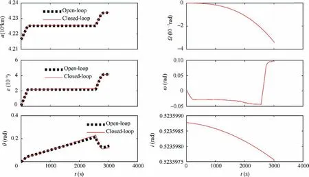
Fig. 9 Illustration of STS’s orbit motion.
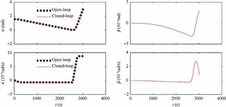
Fig. 10 Illustrations of tether libration motion.
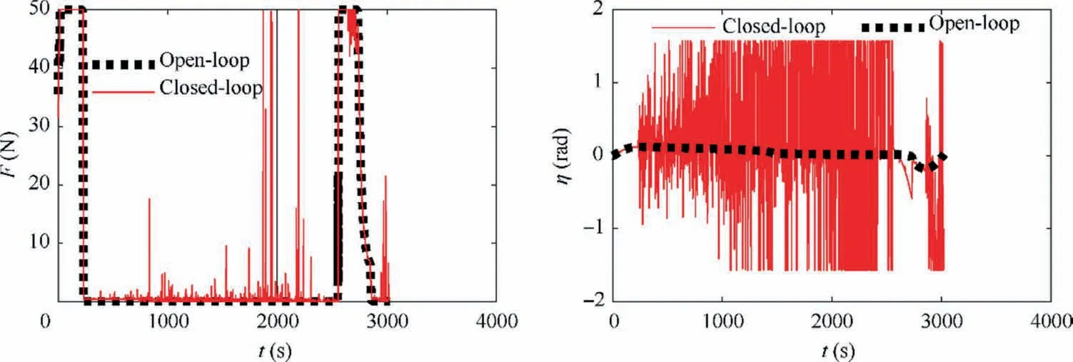
Fig. 11 Illustrations of thrust magnitude and thrust direction.
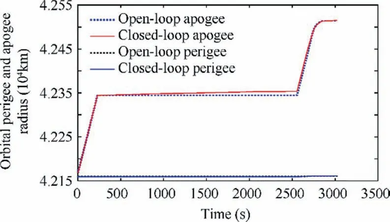
Fig. 12 Illustrations of perigee and apogee radius.
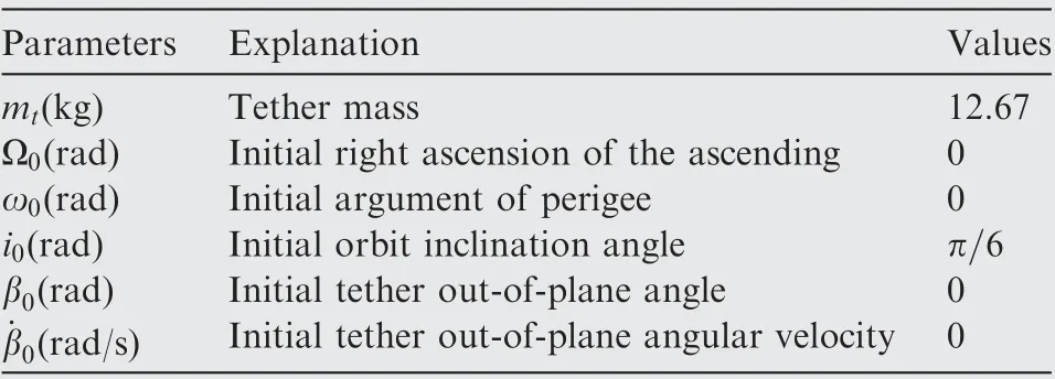
Table 2 Closed-loop control combination initial parameters.
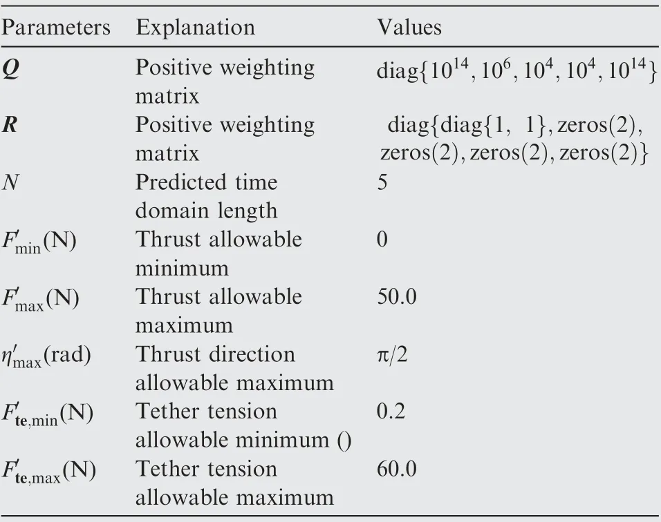
Table 3 Model predictive controller parameters.
To evaluate the overall performance of the proposed scheme, the second stage of maintenance and the third stage of swinging are also simulated and the full trajectories of three stages are given in Figs. 14 to 17. It can be seen from Figs. 14 and 15 that the mission target of the proposed three-stage deorbit is fully achieved.Firstly,the STS is raised to a transfer orbit with the apogee radius equaling to the radius of the graveyard orbit. Then the STS moves on the transfer orbit unpowered to the swing point, i.e., the apogee of the transfer orbit(θ=π).Finally the thrust is turned on for a time period t,and the STS’s rotational speed increases.When the debris is above the tug (α=π), having the largest horizontal speed,the tether is cut off and the deorbit is completed. The thrust during the whole process is given as follow:

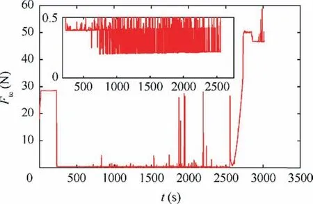
Fig. 13 Illustrations of tether tension.
where the impulse required for the tug, mΔν, in the swinging stage can be calculated by Eq. (24), that is mΔν=1.1734×10kg·m/s. To accelerate the rotation of the STS efficiently, the direction of the thrust in the swinging stage is set perpendicular to the tether and the maximum magnitude of the thrust is adopted. The tether has mass and part of the momentum is transferred to the tether during the momentum transfer process. The increased momentum should be more compared to the value designed in Eq. (23), so the thrust period tis increased by 20 percent in Eq. (36). The propulsion time in the close-loop scenario is increased slightly compared to the designed value to ensure enough velocity increment for the debris. Table 4 gives a summary of the fuel consumption and time cost.It can be concluded that even in the close-loop scenario with more accurate model, the total impulse of the proposed scheme is still more competitive than the Hohmann transfer.The total time cost is almost the same as that of Hohmann transfer.
Fig.17 shows the variation of the tether tension during the three stages. The tether tension is maintained positive during the entire deorbit process, evidencing the safety of the proposed scheme. However, the maximum tether tension reaches 295.8 N in the third stage due to the large rotation rate. The tether tension is considered acceptable in this paper but can be further reduced by modifying the parameters of the scheme.The STS is designed to rotate 5 revolutions per hour, which is conservative. Increasing the final in-plane angular rate in the optimization of the dragging stage leads to a faster rotation for the maintenance stage. This naturally reduces the required impulse for the swinging stage,meaning a slower rotation and a smaller tether tension.
The terminal system states are listed in Table 5 to better investigate the motion after the tether being cut off. At the end of the deorbit process, the orbital radius of the tug and the debris are:

where νis the in-track speed of the STS’s CM. The radial speed of the tug and the debris are the same as the STS’s CM. Using Eqs. (37) and (38), it is possible to estimate the orbit motion of tug and debris after the tether being cut off,which are listed as follows
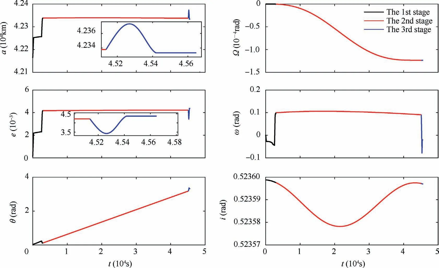
Fig. 14 Illustrations of STS’s orbit motion in three stages.
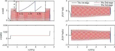
Fig. 15 Illustrations of tether libration motion in three stages.
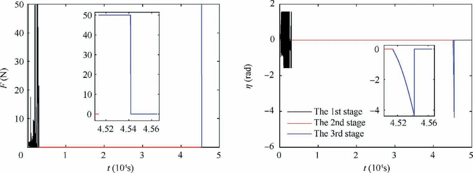
Fig. 16 Illustrations of thrust magnitude and thrust direction in three stages.

Table 5 The values of the system state variables, at the end of the swing period.

Table 4 Summary of the fuel consumption and time of the entire deorbit process (HT donates Hohmann transfer).

Fig. 17 Illustrations of tether tension in three stages.
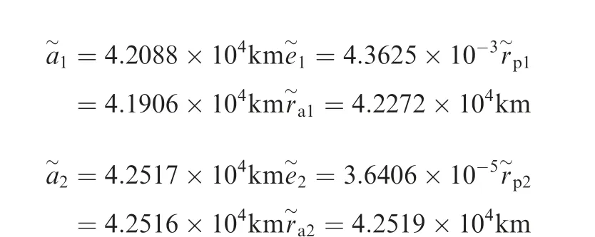
Subscripts 1 and 2 indicate the values for the tug and the debris respectively, while subscripts ‘a’ and ‘p’ represent apogee and perigee respectively. It can be seen from the results that the debris is successfully transferred to the desired graveyard orbit with the perigee 352 km higher than the GEO altitude. However, the perigee of the tug is lower than the GEO altitude, evidencing the momentum exchange between the tug and the debris.
6. Conclusion
For debris removal using tethered space-tug, this paper proposes a fuel-optimal deorbit scheme consisting three stages,namely dragging, maintenance and swinging. An overall fueloptimal trajectory for the dragging stage is solved base on simple model first. Then the designed model predictive controller suppresses the deviations caused by model inaccuracy and environment perturbations. After the dragging stage, the unpowered tethered system enters a transfer orbit with a desired in-plane rotation, which keeps the tether stretched without control. The tug is propelled at the swing point and the in-plane rotation of the tethered system accelerates. The debris obtains enough velocity increment to the graveyard orbit through momentum exchange, when the tether is cut off.Best swing point on the transfer orbit is the apogee.Total impulse cost of the proposed scheme is 0.843 times that required by the Hohmann transfer of single spacecraft with same mass, while transfer time is similar to the Hohmann transfer. Besides, major risks such as the tether slackness and breaking are avoided in the proposed scheme. Neither orbital maneuver nor tether length variation is required to adjust the configuration of the tethered system during deorbit process, thus other risks including collision and tether winding are low. The advantages of fuel saving and safety make the proposed deorbit scheme a good candidate for engineering application of tethered debris removal.
Declaration of Competing Interest
The authors declare that they have no known competing financial interests or personal relationships that could have appeared to influence the work reported in this paper.
Acknowledgment
This research was supported by the National Natural Science Foundation of China (No. 11772023).
 CHINESE JOURNAL OF AERONAUTICS2021年9期
- CHINESE JOURNAL OF AERONAUTICS的其它文章
- Optimal trajectory and downlink power control for multi-type UAV aerial base stations
- Effects of flow parameters on thermal performance of an inner-liner anti-icing system with jets impingement heat transfer
- Effects of wing flexibility on aerodynamic performance of an aircraft model
- Aerodynamic performance enhancement of co-flow jet airfoil with simple high-lift device
- Adaptive fuzzy terminal sliding mode control for the free-floating space manipulator with free-swinging joint failure
- Influence of longitudinal-torsional ultrasonicassisted vibration on micro-hole drilling Ti-6Al-4V
