Influence of longitudinal-torsional ultrasonicassisted vibration on micro-hole drilling Ti-6Al-4V
Guofu GAO, Ziwen XIA, Zhaojie YUAN, Daohui XIANG, Bo ZHAO
School of Mechanical and Power Engineering, Henan Polytechnic University, Jiaozuo 454000, China
KEYWORDS Capability for chip breaking;Longitudinal-torsional ultrasonic assisted drilling;Micro-hole drilling;Periodical characters;Ti-6Al-4V
Abstract As Ti-6Al-4V is a typical hard to machine material, especially in micro drilling aviation parts, chip breaking difficulty is of increasing interest to explore its further development. In this study, Longitudinal-Torsional Ultrasonic Assisted Drilling (LTUAD) was employed to machine Ti-6Al-4V, and its feasibility was evaluated by comparing with Conventional Drilling (CD). By combining periodical characteristics and vibration models (the separated or the unseparated ultrasonic elliptical vibration),the influence of ultrasonic frequency on the intersection characteristics of trajectories were analyzed. And the intersection characteristics were divided into four categories:even periodicity,odd periodicity, non-odd and even periodicity and composite periodicity, indicating different capability for chip breaking. By applying the longitudinal-torsional compound vibration horn, the micro-hole drilling experiment was carried out on machining center. The chip morphology,the thrust force,and the burr height were discussed.Experimental results showed that the morphology of chips presented as smaller and more fragmentary ones in LTUAD compared with continuous helical conical ones and fold-shaped ones in CD.Compared with CD,the average values of the thrust force in LTUAD reduced by 1.98%to 24.9%.According to the burr around the hole exit in both LTUAD and CD, the height of the latter was greatly affected by the drilling parameters. And the burr around the exit of the hole were distributed rather evenly with smaller extension in LTUAD. Consequently, the LTUAD employed in micro-hole drilling was effective.©2020 Chinese Society of Aeronautics and Astronautics.Production and hosting by Elsevier Ltd.This is an open access article under the CC BY-NC-ND license(http://creativecommons.org/licenses/by-nc-nd/4.0/).
1. Introduction
The Ti-6Al-4V, for its superiority properties, has been widely applied where some fields are dominated by high strength-toweight ratio and outstanding corrosion resistance, such as aerospace and medical instrument field. Next to iron and aluminum in manufacturing, it has been one of the indispensable alloy materials, regarded as the backbone of the aerospace industry.However, it is a typical difficult-to-cut material due to the high chemical activity and low conductance coefficient.In traditional semi-closed micro-hole drilling process,the long chips twining around the tool block the inner hole and result in an increase of the drilling force and temperature, and even tool breakage.
Ultrasonic-assisted drilling (UAD), as a novel machining method in which the longitudinal vibration is applied along the tool axil, has been verified as a rather effective method for difficult-to-cut materials, such as titanium alloy and Nibased alloy.Considerable works have illustrated that UAD tool separates periodically against the machining surface in high frequency (usually more than 20 kHz), which changes the mechanism of the chip forming, and improves the severe cutting environment, as well as the surface quality of the machined workpiece.
A recent work of Zhao, et al.studied experimentally the incidence angle of ultrasonic waves on horn. And the experimental results showed the average cutting force with the optimal incidence angle reduced by 46% in comparison with CD.UAD CFRP/Ti was experimentally conducted supported by Shao, et al.,who found that the thrust force and torque decreased by about 20% and 32% respectively. Wang, et al.established the force model with consideration to the interactive action between the cutting force and the ultrasonic vibration,and explained the mechanism of the critical cutting force in ultrasonic machining.
With regard to researches on chip morphology and surface roughness in drilling,it was found that the chip was small and curly,with large deformation in UAD,and the value of surface roughness and accuracy of hole was better than those in CD.It was studied experimentally by Nie, et al.in micro-hole UAD stainless steel. The experimental results presented the short chips with large curvature deformation and the decreased roundness error of machined hole.Liang,et al.verified the cutting temperature and surface roughness were promoted obviously in UAD Ti-6Al-4V. In addition, the formula of axial cutting thickness was established and the chip breaking condition given by Adachi K from Osaka University of technology.Chen, et al.deduced the motion trajectory of the cutting edge and the chip thickness equation related to phase difference of ultrasonic waves, and verified the chip breaking conditions by experiments.
In recent years, processing with unseparated ultrasonic vibration assistance has drawn more and more attention along with the development of high-speed cutting theory, in which the tool is difficult to separate from the machining surface completely. Researches based on separated ultrasonic cutting(cutting velocity is no more than 2πfA, f and A is the frequency and amplitude of UAD respectively) introduced a misunderstanding that the effectiveness in unseparated ultrasonic machining is inferior to that in separated ultrasonic machining. Li, et al.conducted an experimental of unseparated ultrasonic elliptical cutting, indicating the relatively effective drop of cutting force and value of surface roughness.
The higher the tool revolution speed ensuring the linear cutting speed to improve the machining efficiency, the harder to separate the tool from the machining surface in micro-hole UAD.In order to explore the motion characteristics of cutting edges and fundamental of chip formation, the trajectories of cutting edges in LTUAD were analyzed to explain the weakness of vibratory component in high tool revolution speed based on combining periodical characteristics and vibration models of ultrasonic waves. Furthermore, the influence of cutting and acoustic parameters on thrust force, the morphology of chips and the burr height were studied experimentally in micro-hole LTUAD Ti-6Al-4V.
2. Kinematic analysis in LTUAD
2.1. Trajectory equation of cutting edge
The trajectory of cutting edge changed when the tool was applied high frequency vibration.As shown in Fig.1,a typical LTUAD system mainly consists of the following components.The ultrasonic generator generates a certain high frequency electrical sinusoid signal and tracks the frequency according to the cutting load. The wireless power transmission system was employed to transmit the high frequency signal from the excitation coil fixed on the spindle frame to the induction coil set on the rotating holder, in which a piezoelectric transducer vibrates longitudinally along with the received high frequency signal based on the converse piezoelectric effect.Therefore,the electrical energy is transformed into the mechanical vibration energy presenting usually micrometer-level amplitude. The longitudinal amplitude of the transducer is amplified by the horn with spiral grooves, which generate the ultrasonic torsional vibration simultaneously as well. Finally, the longitudinal and the torsional vibration compound to form elliptical vibration at the tool end.
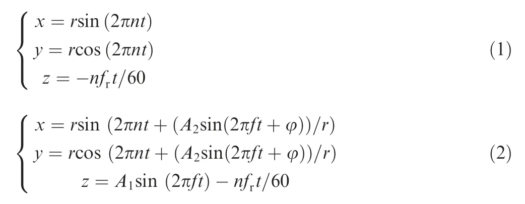
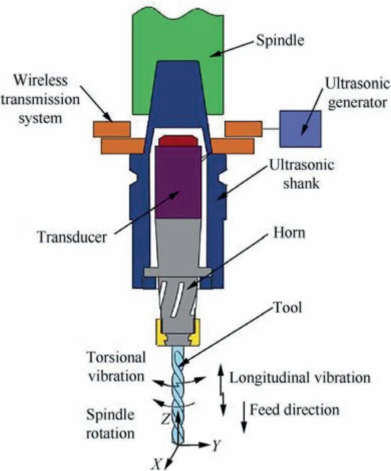
Fig. 1 A typical LTUAD system.
Taking the center of the tool as the origin,and establishing the Cartesian coordinate system as shown in Fig.1,the trajectory equation,in CD and LTUAD,was obtained respectively:where r is the radius of the drill bit(mm),n is the spindle speed(r/min), fis the feed rate (μm/r), Aand Aare the longitudinal and torsional amplitude (μm), respectively. φ is the phase difference of longitudinal and torsional vibration.
As shown in Fig.2,the cutting element on the main cutting edge was equivalent to that in an oblique model, and in the angle reference system P, P, P, Pwere defined as the basal plane, the normal plane, the orthogonal plane and the cutting plane respectively. In addition, the main cutting angles were defined on the reference system, including the rake angle γ,the clearance angle αand the inclination angle λ.Rather than a spiral curve of equal pitch in CD, the effect of LTUAD makes the space trajectory complex and elliptical. In CD, the element of a cutting edge moves along with the spiral line according to feed motion and generates stable shear band and continuous chips, some of which twist off the cutter unavoidably,as shown in Fig.2(d).However,the cutting edge assisted with the longitudinal-torsional ultrasonic vibration moving from the point Pto Pin one regular ultrasonic period, as shown in Fig. 2(e). And the cutting edge separates against the workpiece and chip from Pto P,as it is included in the processed track Pto P. Therefore, LTUAD improves the workpiece-tool contact state and the ability of chip breaking.
2.2. Kinematic characteristics for a single cutting edge
In order to analyze the weight ratio of cutting parameters and acoustic parameters on the trajectories of cutting edges in LTUAD, velocity coefficient K was employed:

where V is the liner velocity (m/min), Vis the ultrasonic critical velocity (m/min).
The elliptical motions for different K values in LTUAD are classified as either a separated one or an unseparated one. As the track line of a cutting edge in Fig. 3, assuming Tas the starting point of one period (T-T-T-T), Tis the initial point of actual cutting since TTis included in the trajectory of the previous period,which is actually the vacant cutting trajectory.In addition,torsional and longitudinal vibration moving simultaneously in the direction of receding when reached T. Afterwards, the composite vibration of longitudinal and torsional driving the tool to evacuate from processing zone up to the next cutting point T. Consequently, TTis the actual cutting trajectory,and TTis the vacant cutting trajectory. As the rotational speed growing, the length of TTbecomes smaller and smaller, and disappears eventually. In Fig. 3(b), the return action has not happened because of no intersection of trajectory for the unseparated cutting.
Considering the axial feed of cutting edges, its trajectories are interfered with the previous one after the cutting edge rotates for one circle, as shown in Fig. 4. According to the axial feed per revolution, the current trajectory and the previous one keeps the same characteristics apart from the difference of Z-direction dislocation. Accordingly, the theoretical section of a unit chip section is a sector enclosed by BCEF formed by the trajectory of cutting edge. This phenomenon occurs as the number of periods of the ultrasonic vibration per revolution (NPR) is an integer and the frequency of ultrasonic vibration is constant.
2.3. Kinematic analysis for double cutting edges
Coupling with the change of the ultrasonic frequency, the relative positions of the both cutting edges with symmetrical arrangement change periodically during the tool rotates one cycle.According to the value of NPR affecting the intersection characteristics of trajectories, the intersection characteristics are divided into four categories: even periodicity, odd periodicity,non-odd and even periodicity and composite periodicity.NPR is expressed as:
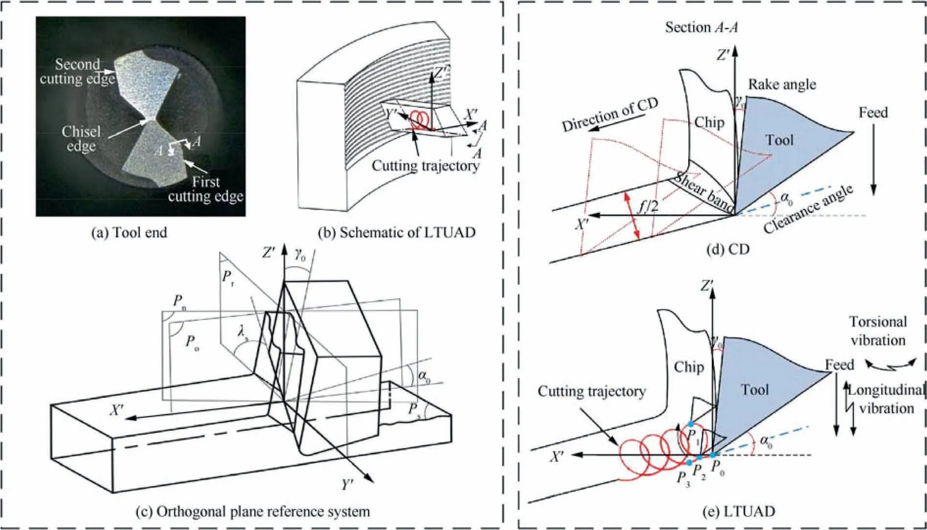
Fig. 2 View of cutting element on main cutting edge.
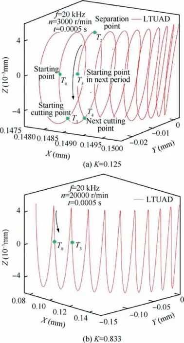
Fig. 3 Motion trajectory of cutting edge with different K.
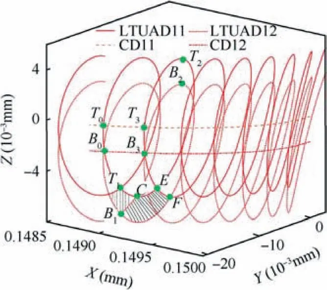
Fig. 4 One cutting edge motion characteristic in separated elliptical motion.

2.3.1. Even periodicity trajectories analysis
The intersection characteristics of trajectories present even periodicity for even NPR. As shown in Fig. 5, supposing M and N represent the outermost point of the first and the second cutting edge respectively, Mand Nare the different location of both cutting edges on the trajectories. The subscript is the number of semi-revolutions of tool rotation. At the time 0 s without feeding, M and N is locating at Mand N, as the starting points of both cutting edges respectively (Nis invisible under the current perspective). M moves from Mto M,and N from Nto Nafter the tool revolves half cycle. Therefore,the axial distance between Mand Nis f/2 and it is same for Nand M.Moreover,this phenomenon repeats along with the tool rotation, which is observed in even periodicity LTUAD no matter whether the cutting trajectories behave unseparated (K=2.5, NPR=20) or separated (K=0.125,NPR=400) elliptical motion. Consequently, the characteristic of the even periodicity trajectories is that the trajectory generated by the second cutting edge is always consistent with that by the first one in shape, and the phase difference is an even multiple of π. Furthermore, the actual cutting length L (from Cto D) with separated motion can be expressed as:where the coordinate of Cand Dare obtained by simulation.Corresponding to Eq. (5), the cutting arc length is 2.38 μm,and the entire arc during a unit ultrasonic period is 31.27 μm.


Fig. 5 Trajectories of even periodicity with different K.
As Fig.5(a),the excessive value of K weakens the vibration so seriously that the vibratory component (The number of vibration periods in the cutting unit distance) reduced obviously as the tool rotates a unit cutting length, without contribution to form multi-trajectories intersection. The spatial regions produced by two different K in a unit time are I and II respectively, as shown in Fig. 6. Zand Zare the space coordinate points of the tool tip in a unit time, P is the intersection projection of the longitudinal and the torsional amplitude. Within a unit cutting time, P is same both in the two regions, but X-directional cutting distance is different greatly,XXof II region is larger than XXof I region apparently.
2.3.2. Odd periodicity trajectories analysis
For the odd periodicity trajectories,both trajectories generated by the two cutting edges are exactly same but the phase difference with an odd time of π.
The odd periodicity trajectories at a certain time were demonstrated in Fig. 7. At the beginning, M and N is located at the point Mand N, then N reaches the point Nafter the tool rotates half a revolution. Apparently, M moves toward the crest while N moves toward the trough,which makes their velocity same but direction opposite. Consequently, the characteristic of the odd periodicity trajectory is that the trajectory generated by the second cutting edge is always opposite to the trajectory that generated by the first cutting edge one in shape.The closed chip section region SS(the unseparated type)and ECDF(the separated type) is formed theoretically without relationship to K values, differing from even periodicity trajectories.
2.3.3. On-odd and even periodicity trajectories analysis
NPR corresponding to the resonance frequency generated by the ultrasonic power is usually not an integer value.For simulating such motion, it is key to control the NPR values. The unseparated (K=2.569) and the separated (K=0.117) elliptical trajectories with non-odd and even periodicity were illustrated in Fig. 8. The characteristic of non-odd and even periodicity is that the relative positions M, N, Mof M and N no longer maintain regularity mutually.The closed chip section region SS(the unseparated type) and ECDF(the separated type) is formed theoretically because of interference of trajectories.
2.3.4. Composite periodicity trajectories analysis
The intersection of multiple trajectories generated by different periodicities were discussed based on the stable frequency in LTUAD. Actually, the resonance frequency, amplitude and impedance of the ultrasonic system fluctuates simultaneously with the cutting load.
Accordingly,the phenomenon of frequency shifting inevitably in LTUAD makes it rather difficult to analyze the kinematic characteristics. Fig. 9 presents five trajectories with different frequencies were combined to simulate such complex periodicity.From Fig.9(a),the intersection of adjacent trajectories with stable amplitude and variable frequencies witnesses regularly many pea-shaped areas, and the theoretically generated chip section unit results from the mutual intersection among the‘pea’units.In addition,in Fig.9(b),the intersection of trajectories with variable amplitude and frequency demonstrates the irregular theoretical chip section unit, with contribution to chip breaking.
2.4. Influence of K on chip breaking
It is difficult to observe experimentally micro cutting process to discuss the chip breaking mechanism.Therefore, the finite element method analysis, based on Abaqus/Explicit, was employed to clarify the mechanism, as shown in Fig. 10. For the cutting model, the equivalent cell of the cutting edge ran corresponding to the oblige cutting based on Fig. 2, and the Ti-6Al-4V workpiece adopted Johnson-Cook constitutive model, and the tool was regarded as rigid body.The rake angle, clearance and inclination angle of tool were 7°, 12°and 20° respectively.
For LTUAD simulation in Abaqus, the boundary conditions conflicted when the feed motion of the tool was coupled with the longitudinal vibration, so did the spindle rotational motion coupled with the torsional vibration. A new application method was adopted to define this complex motion.Firstly, the longitudinal velocity Vand the angular velocity ωin LTUAD were obtained according to Eq. (2).

Vand ωwere functions of the machining parameters and the acoustic ones. Then, by using periodic amplitude function from Abaqus function library, the information of Vand ωcombining the machining and the acoustic parameters were assigned to the tool reference point to achieve longitudinal and torsional compound motion.
The microscopic phenomena of chip breaking in LTUAD Ti-6Al-4V were displayed including three different motions for every K.Taking the cutting edges radius and material properties of workpiece into account, the chip shape behaved less regular. Moreover, the surface residual height was pressed by flank face so that the regular geometric theoretical chip section unit was hard to form. But its capability of chip breaking still remained.
Particularly, the tool separated from machining surface as K=0.125. The separated cutting became rare when K increases, still maintaining the capability of chip breaking;and the chips were not smaller and more fragmentary than those of small K,indicating the chip continuity was increasing gradually. However, the continuous chips always flowed out close to the rake face in CD.
On the one hand, the tool trajectory, in LTUAD, provides the geometric chip breaking condition. The smaller K will result in more trajectory intersection. On the other hand, the chip breaking not only has relations with periodicity trajectories, but material properties. The stress wave velocity generated by the high-frequency impact of the tool is much greater than the cutting speed in LTUAD. Although the tool has not been cut in, the mechanical behavior has occurred in the area to be processed. In the superimposed area of stress waves, some micro cracks occurred if the stress exceeded the ultimate strength of material.The stronger the dynamic impact, the greater the effect of the stress wave. The Mises stress state of a node (the red point) for different K was presented in Fig.11.There was a large difference in a unit cutting distance in Fig. 11. Although the tool has not yet cut into the node, it has already brought about an alternating stress state under the effect of the stress wave at K=0.125.As the spindle speed increase, NPR decreases, showing that the effect of ultrasonic impact weakened, so that the difference of stress curve became small between LTUAD and CD. In addition,in Fig. 10, for K=0.125, the phenomenon of chip breaking was more obvious than K=1.5, as well as crack forming. It indicates that the smaller K is in favor of chip breaking.
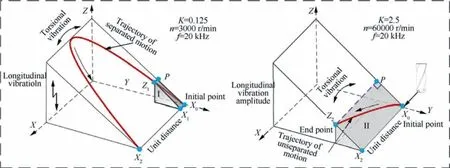
Fig. 6 Vibratory component with different K.
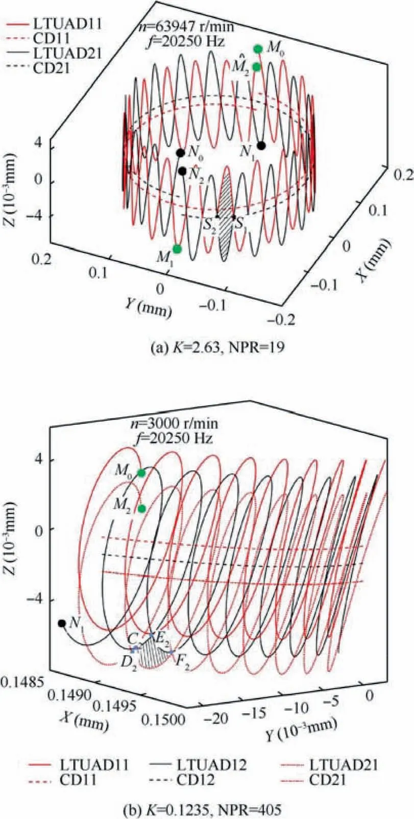
Fig. 7 Trajectories of odd periodicity with different K.
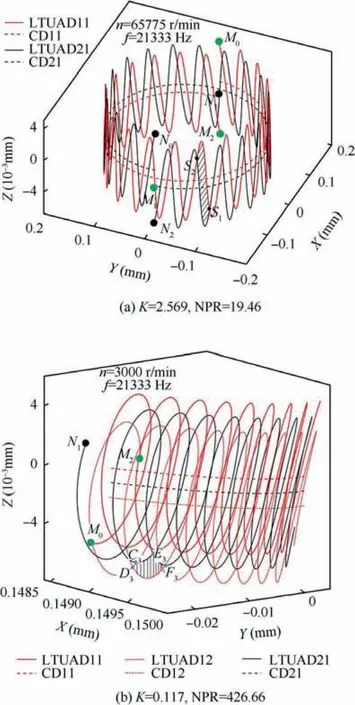
Fig. 8 Trajectories of non-odd and even periodicity with different K.
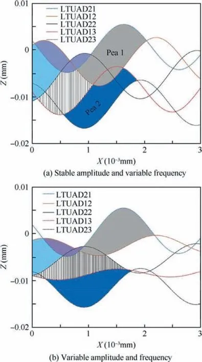
Fig. 9 Trajectories of composite periodicity.
3. Experimental setup
3.1. Description of experimental conditions
The workpiece material was titanium alloy Ti-6Al-4V. The specific parameters of the workpiece properties and the tool were listed in Table 1 and Table 2.Taking the stiffness of drill and dry cutting into account,the peck drilling was employed in this experiment, in which the tool was lift after each feed 0.3 mm within each peck drilling stage.
Based on the LTUAD horn with resonance frequency 28 kHz developed by quarter-wavelength theory, the experiments were conducted on JDLVG600E A10H. a machining center from Beijing JD Group. As illustrated in Fig. 12, the dry-cutting experimental setup mainly consisted of a machining center, a wireless transmission device, a longitudinaltorsional ultrasonic vibration system,a force measuring system Kistler 9257B,a high-speed camera VW9000 to capture the inprocess dynamic chip, coated drills and Ti-6Al-4V samples.The circular runout error of the spindle was within 0.005 mm.
In order to study the influence of K on micro-hole LTUAD,a single factor test was designed as shown in Table 3,to study the capability of chip breaking for different K.In addition,it is necessary to adopt high rotational speeds and small amplitudes to prevent the drill from heavily wearing and even breaking in micro-hole LTUAD Ti-6Al-4V. Therefore, the experiments were carried out for the K value ranged from 3.24 to 16.2,based on unseparated cutting according to Section 2.
3.2. Measurement procedure and conditions
The piezoelectric dynamometer, Kistler 9257B, was employed to measure the thrust forces in experiment. The charge signals outputted by the dynamometer were transformed into voltage signals through a multi-channel charge amplifier,then the voltage singles were transformed into digital signals and acquired by the data acquisition system.The force data were analyzed in computer by Labview software.A high-speed camera,Keyence VW9000,was applied to observe chip formation in micro-hole drilling.
A laser displacement sensor, Keyence LK-G10, was employed to measure the longitudinal amplitude in axial direction when the laser beam focused on the tool end,but it failed to acquire directly the torsional amplitudes in circular direction.The torsional amplitude can be obtained by indirect measurement.The measured values were the average of five measurements on different positions along the radial direction.The results indicated that the longitudinal torsional ratio was about 1:0.6 according to the fitting curve.
A digital microscope, Keyence VHX-2000, was used to observe the morphology of chips and the exit burr.
4. Results and discussion
4.1. Chip morphology
The characteristics of dynamic chips filmed by high speed camera were illustrates in Fig. 13. In mic ro-hole CD Ti-6Al-4V,mass chips piled up around the entrance of the hole and twined up the tool,and only a few fragmental chips scattered nearby.The continuous long chips were difficult to break and easy to block the spiral grooves so as to worsen the machining stability severely,leading to the tool wear and deflection up to fracture.
However, in micro-hole LTUAD Ti-6Al-4V, a large number of fragmental chips were expelled from the machining hole and only a small amount of broken long chips wound on the tool. As K reduced from 8.1 to 3.24, the broken chips became smaller and thinner,and the winding ones on the tool were less obviously. It indicated that the smaller K enhanced the capability of chip breaking.
Several typical chip morphologies both in micro-hole CD and LTUAD Ti-6Al-4V were displayed in Fig. 14. The chip generated in CD behaved mostly the continuous helical conical and the fold-shaped ones, while the fragmentary fan-shaped and the band-shaped chips dominated in LTUAD. Under the observation field with the magnification 100 times as A and A1, it witnessed a piece of rough helical conical chip for CD, rather much debris for LTUAD.
At the initial stage in CD, the short chips were stacked rarely in the spiral grooves, so the regular continuous spiral conical chips were discharged smoothly. With the increase of drilling depth, chips piled up gradually in the spiral grooves squeezed constantly to be stacked shape. For micro-hole LTUAD Ti-6Al-4V, as shown in Fig. 15, the torsional vibration caused pulse cutting in the circumferential direction,resolved into pulse intermittent cutting in normal and tangential directions.And the repeated pull-out action corresponding to the longitudinal vibration along tool axil amplified further the cracking points caused by the shock of torsional vibration.

Fig. 10 Microscopic phenomenon in cutting Ti-6Al-4V with different K.
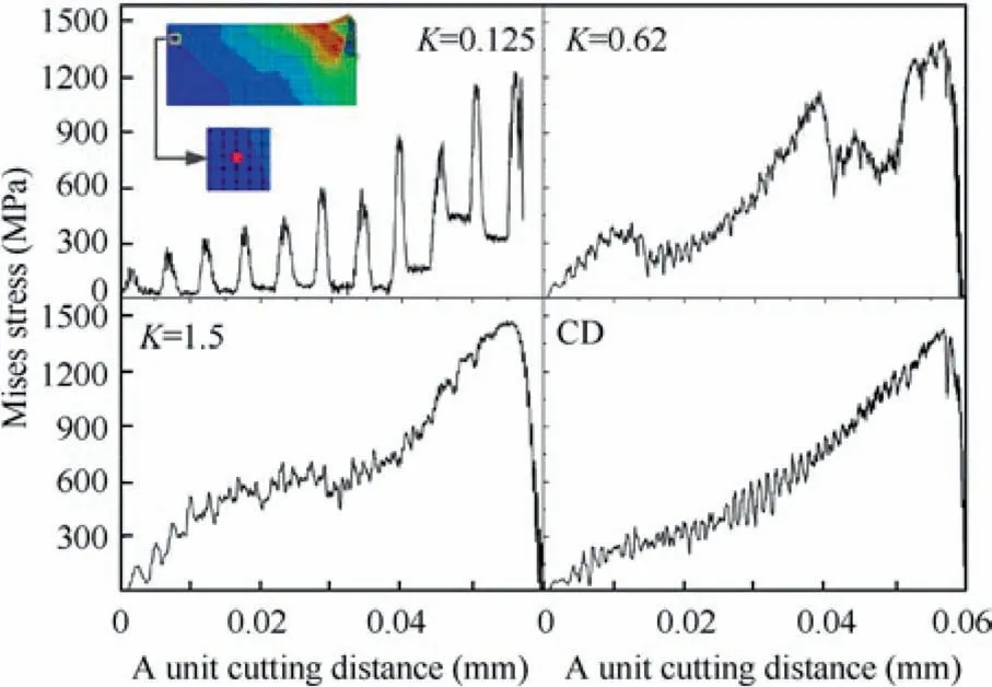
Fig. 11 Stress state of one node.

Table 1 Material properties of Ti-6Al-4V.
Obviously,for LTUAD,the capability of chip breaking,as shown in Fig. 14(b), still existed, but it weakened gradually.Both for K=3.58 and 4.62, the fan-shaped chips dominated the process. The fact that the fracture phenomenon occurred before the continuous spiral chips formed when the chips flowed along the rake face, mainly because of the intermittent impact in LTUAD.As the spindle speed increased,the amount of material removed per unit of time increased and the amount of vibration in unit cutting distance decreased, which led to such fan-shaped chips to appear folded. When K reached 6.94, it was found that the ultrasonic action made the chip no longer curl, and the capability of chip breaking has been significantly weakened.
In Fig. 16, the cracks on thicker chips in Fig. 16(b) were more than those in Fig. 16(a), and a few potential cracking points were growing, causing the thicker chips to fracture early. That meant the suitable feed rate was beneficial to generate certain thickness chips which was susceptible to the stress concentration. Consequently, the feed rate had influence on the chip breaking.
Therefore, K characterized well the effect of parameters on chip breaking. Moreover, the chip breaking, as a complex state, is not only relation with kinematic, but material property. Overall, the elliptical vibration generated by ultrasonic excitation caused cutting trajectories of cutting edges to intersect, which made contribution to the chip breaking and flowing out. In terms of material’s features, the internal stress imposed by both the ultrasonic impacts and cutting shear action exceeded easily the fracture stress limit of Ti-6Al-4V,and chips broke easily in micro-hole LTUAD,in favor of chip removal.

Table 2 Tool parameters.
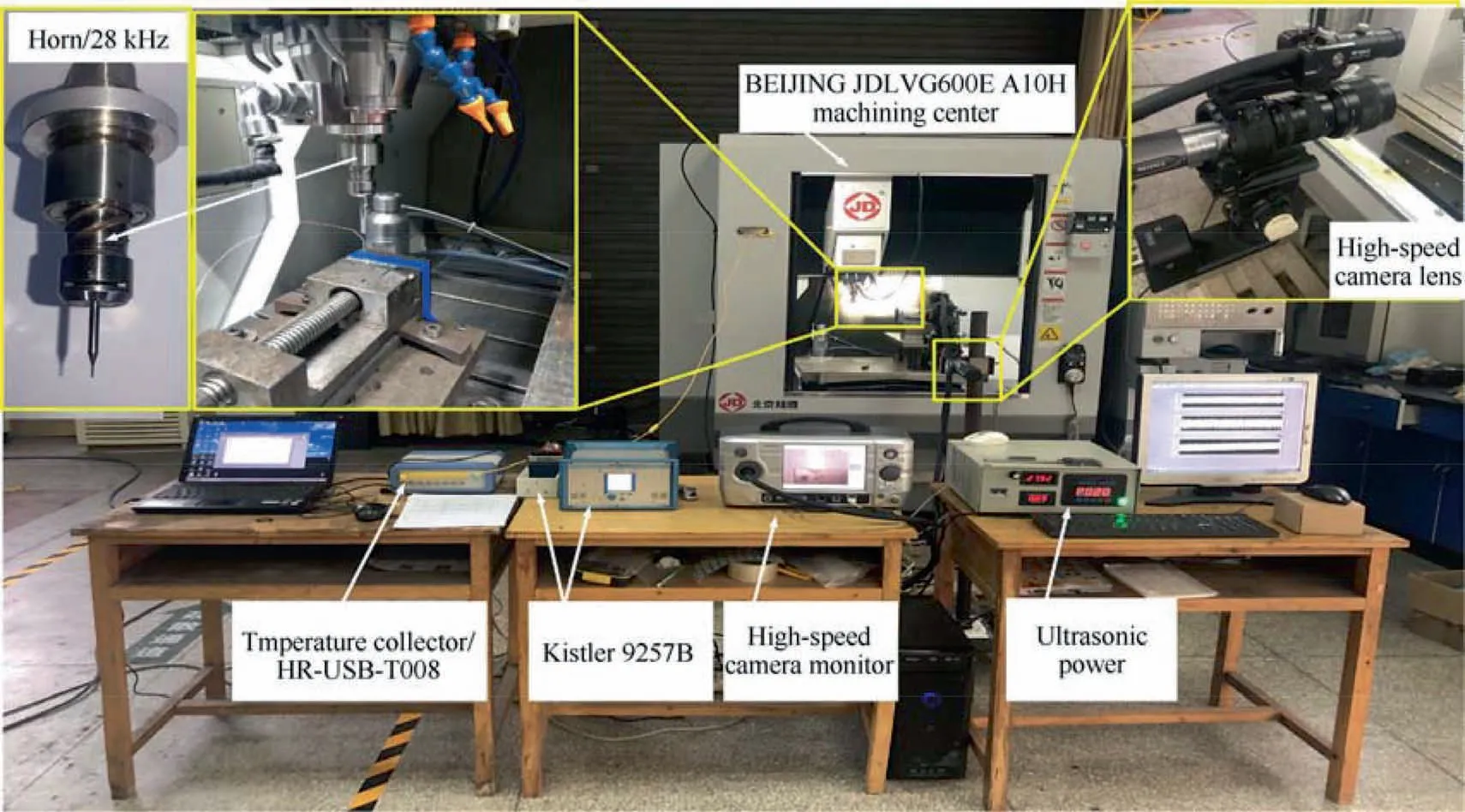
Fig. 12 Experimental setup for LTUAD Ti-6Al-4V.

Table 3 Experimental parameters.
4.2. Thrust force
The thrust force curves in micro drilling Ti-6Al-4V were shown in Fig. 17. Due to the poor cutting performance of the chisel edge, grew up sharply for an instant as soon as the tool engaged with the workpiece.After the cutting edges dominated the machining, the thrust force gradually reached a stable state, then fluctuated within a certain range.
The average values of the thrust forces in micro drilling Ti-6Al-4V were shown in Fig. 18. The data were calculated according to average value within five stable micro-hole drilling. As shown in Fig. 18(a), the thrust force appeared a decreasing trend against the spindle speed whatever processing method, while it rose up as rotation speed was over 16,000 r/min. The cutting force decreased by 7% to 10% in microhole LTUAD. The drop ratio of the thrust force in LTUAD to that in CD reached the maximum value 10.06% as the spindle speed was 14,000 r/min, and the minimum value 3.49% as the spindle speed was 18,000 r/min. The minimum drilling force was 10.61 N as the speed was 16,000 r/min.
That resulted mainly from the cutting edges run in elliptical trajectories in micro-hole UAD Ti-6Al-4V. The improvement of ability of chip breaking and flowing out, fragmentation and miniaturization of chips relieved the tool wear. A large instantaneous speed and acceleration at a small displacement exerted on the cutting edges due to the effect of ultrasonic vibration made the material soft and plastic flow easy. And the instantaneous velocity in the outmost point of cutting edge both in CD and LTUAD represented respectively:

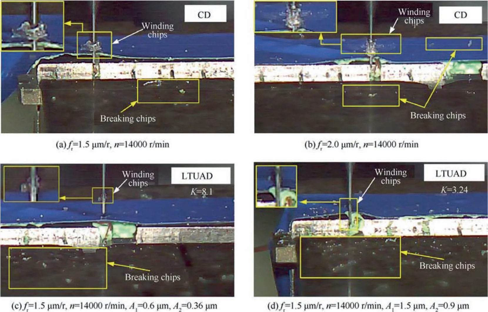
Fig. 13 Dynamic chips by high speed camera.
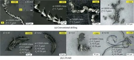
Fig. 14 Morphology of chips by digital microscope.
The more the spindle speed, the higher the cutting temperature.The shear yield strength of the material decreased under the high cutting temperature relating to the high spindle speed,so the shear stress of material removal was reduced in processing.Moreover,the contact area between the chip and the rake face increased with the spindle speed within a unit time, conducive to the birth and growth of built-up edges. The actual rake angle increasing along with the size of built-up edges contributed to the drop of the thrust force. On the other hand,overgrowing speed induced the reduction of the height of built-up edges and severe tool wear. The force trend in Fig. 18(a) indicated that LTUAD lost its advantages as the spindle speed was over 18,000 r/min, weakening the impact of ultrasonic vibration. Meanwhile, the large K value by high spindle speed diminished the capability of chip breaking,which was consistent with the morphology of chips in Fig. 10 and Fig. 14(b).
The influence of the feed rate on the thrust force was demonstrated in Fig. 18(b). The minimum value of force was only 8.9 N as the feed rate was 0.5 μm/r. And a rise trend was observed along with the feed rate both in CD and LTUAD. The chip thickness within per revolution increased as well, resulting in the large cutting power and severe tool wear.
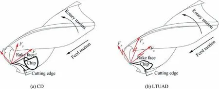
Fig. 15 Chip formation schematic of drilling Ti-6Al-4V.
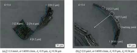
Fig. 16 Size of chips.
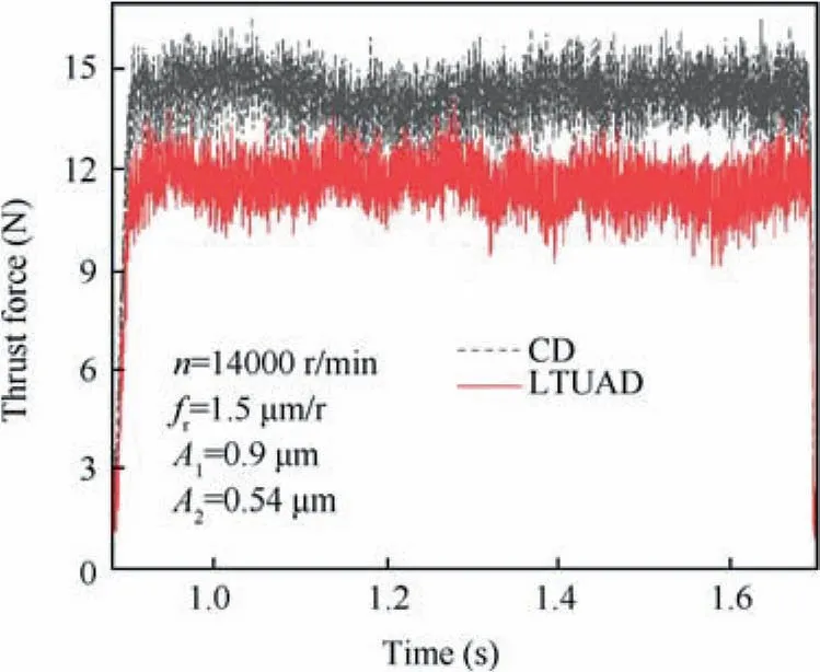
Fig. 17 Thrust force in one stage of peck drilling.
In addition, from Fig. 19, it witnessed the thrust forces deceased against amplitude increasing in n=14000 r/min,f=1.5 μm/r.The cutting force was only reduced by 1.98%as amplitude Awas 0.18 μm,while the thrust force decreased by about 24.9% as amplitude was 0.9 μm. Comparing with the morphology of chips, it indicated that small value of K was helpful to break chips, and conducive to reduction of the thrust force as well.
4.3. Exit condition
In the process of micro drilling, burr was formed around the exit of the micro holes on the workpiece surface. As the tool ran close to the bottom of the hole, the poor material’s resistance to deformation due to the decreasing thickness of the workpiece at the front end of the transverse edge was insufficient to generate stable cutting chips.The cracks initiated generally around the transverse edge of the tool and sprouted out,and finally burr came into being due to high toughness and ductility of Ti-6Al-4V as the cutting edges drilled out workpiece.
As shown in Fig. 20, the exit burr, on the whole, was distributed evenly with smaller extension in LTUAD than that in CD, and the roundness error of hole was lower than the later. That resulted from the different stress state of the materials near to exit,the shear force was occurred in LTUAD,but the tensile force in CD.In addition,the intermittent impact,in LTUAD, could reduce the deflection of material along the axis, and in favor of the cutting performance of the tool as well.
A trend has been seen in Fig.21(a)that the higher the spindle speed,the larger the burr height,in CD.In dry cutting,the spindle speed exerted a critical role to the cutting temperature.In the critical state of burr formation, chips failed to be formed,meaning the cutting heat was accumulated in the area between drill and material. And the low thermal conductivity of Ti-6Al-4V resulted in local temperature rising, thereby the plasticity of the material was improved. Besides, the low cutting force lightened the material’s deformation and extension at the hole exit, so that the difference of burr height was not obvious from 12,000 r/min to 16,000 r/min. However, the greater temperature and force made the burr height reach the maximum at 18,000 r/min. For LTUAD, the cutting performance, temperature and force were improved, which made it an unclear change trend, but the average burr height was smaller about 33.4% than that in CD, with the maximum up to 44.9%.
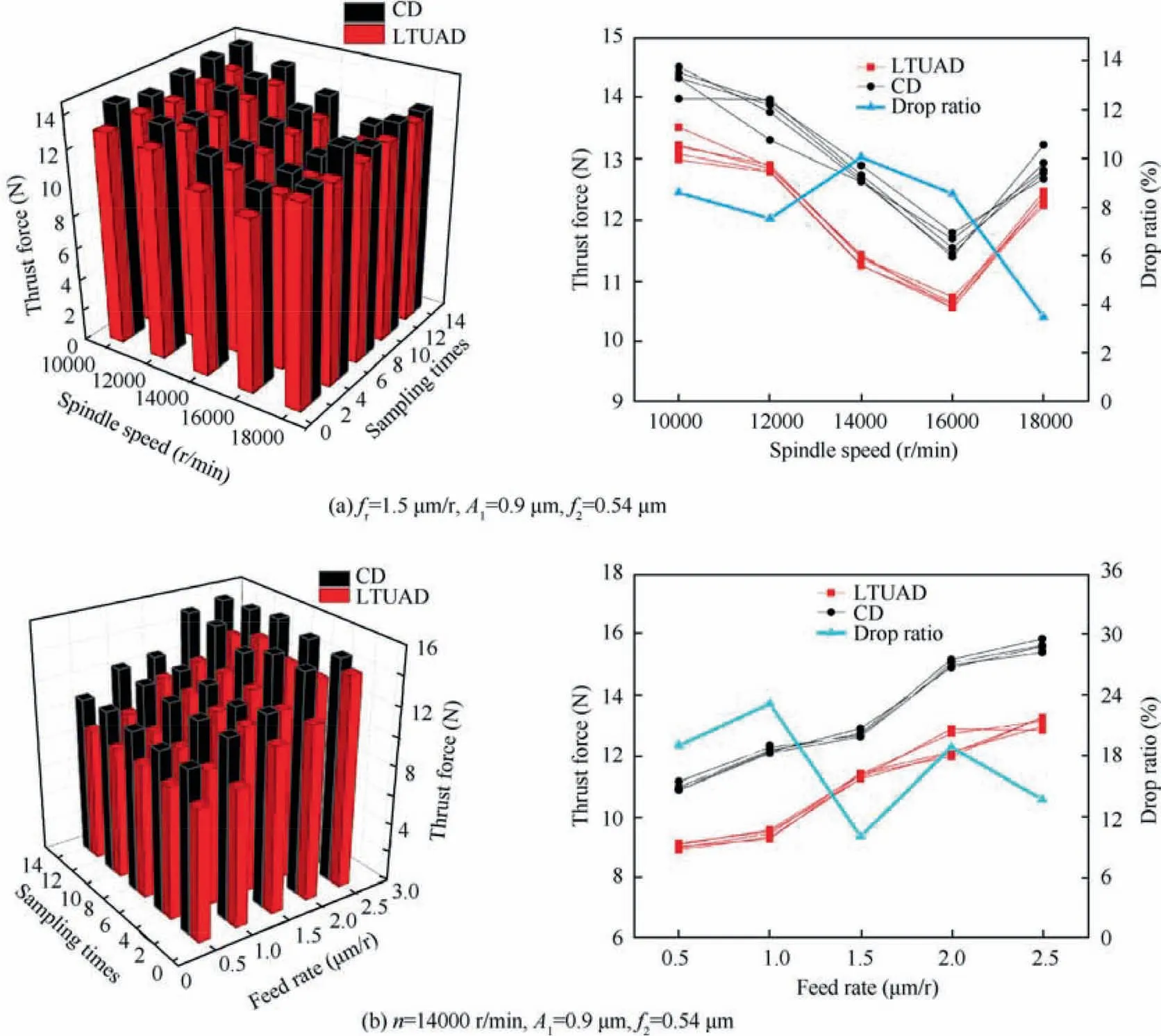
Fig. 18 Fluence of spindle speed and feed rate on thrust force.

Fig. 19 Effect of ultrasonic amplitude on thrust force.
According to Fig. 21(b), in CD, the burr height decreased and then increased as the feed rate increased, which resulted from the burr generated by tearing rather than cutting. In addition,overgrowing feed rate resulted in an increase of burr height, corresponding to the poor tool stiffness that made the tool deflect in processing, as shown in Fig. 20(a). It presented that the appropriate feed was beneficial to reduce burr height in micro drilling. Moreover, not only the distribution of burr in LTUAD was even, but also the exit roundness was prior to that in CD. In addition, the overall fluctuate range of burr height, according to Fig. 21(c), was small, mainly because of the small amplitude value. The drop ratio of burr height rose from 33.1% to 38.4% as the amplitude upped from 0.3 μm to 1.5 μm.Although the improvement was limited,the growing amplitude could relieve the burr formation.
5. Conclusions
1. By analyzing the four kinds of periodical characteristics and the two vibration models, including separated and unseparated LTUAD, and the geometric theoretical chip section unit was established. The principle of ultrasonic chip breaking was discussed.In addition,the effect of overgrowing speed on the weakening of vibratory component was explained. And the influence of velocity coefficient K on chip breaking is verified by finite element method and experiment.

Fig. 20 Burr morphology of micro holes.
2. The ability of chip breaking was improved by ultrasound,and the chip shape was mainly discontinuous and fanshaped and band shape.CD was mainly continuous helical conical chips or fold-shaped chips. In addition, the chip morphology in ultrasound may also be continuous with overgrowing spindle speed, and in favor of chip breaking under suitable feed rate.
3. The mean thrust force of LTUAD was achieved by comparison of CD. The influence of speed variable on drop ratio of the mean thrust force was not obvious than that of feed variable, reduced by 7.54% to 11% and 10.06%to 23.1% respectively. The increase of amplitude can effectively reduce the thrust force, reduced by 1.98% to 24.9%.It indicated that the larger K, the weaker the ultrasound effect.
4. The height of exit burr was distributed evenly with smaller extension in LTUAD than that in CD,which was improved from 17.2% to 44.9%. In addition, it is helpful to decrease burr height by increasing amplitude.
Declaration of Competing Interest
The authors declare that they have no known competing financial interests or personal relationships that could have appeared to influence the work reported in this paper.
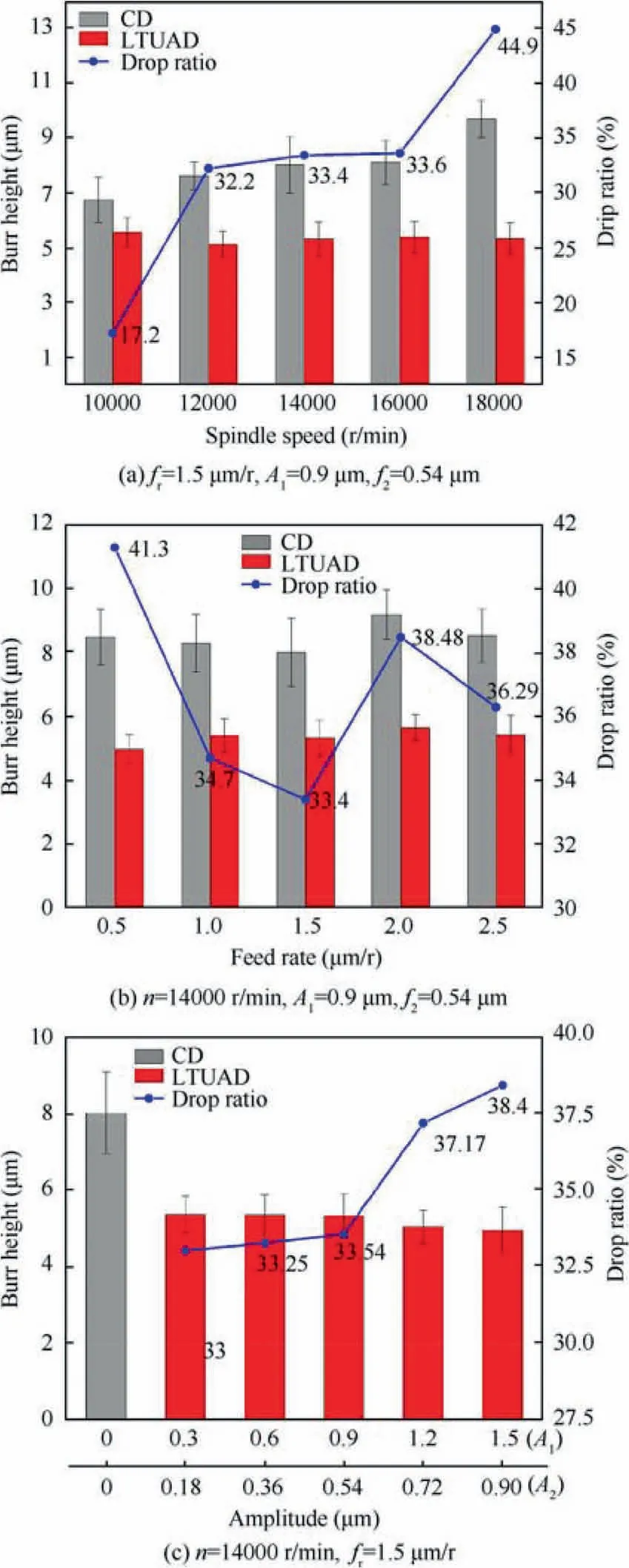
Fig. 21 Influence of processing parameters on burr height.
Acknowledgement
This study was supported by the National Natural Science Foundation of China (No. 51875179).
 CHINESE JOURNAL OF AERONAUTICS2021年9期
- CHINESE JOURNAL OF AERONAUTICS的其它文章
- Optimal trajectory and downlink power control for multi-type UAV aerial base stations
- Effects of flow parameters on thermal performance of an inner-liner anti-icing system with jets impingement heat transfer
- Effects of wing flexibility on aerodynamic performance of an aircraft model
- Aerodynamic performance enhancement of co-flow jet airfoil with simple high-lift device
- Adaptive fuzzy terminal sliding mode control for the free-floating space manipulator with free-swinging joint failure
- Response and stabilization of a two-stage axial flow compressor restricted by rotating inlet distortion
