A newly bio-inspired path planning algorithm for autonomous obstacle avoidance of UAV
Yoming ZHOU, Yu SU, Anhun XIE, Lingyu KONG
a School of Aeronautic Science and Engineering, Beihang University, Beijing 100191, China
b Intelligent Robot Research Center, ZHEJIANG LAB, Zhejiang 311121, China
KEYWORDS Obstacle avoidance;Path planning;Plant growth;ROS;UAV
Abstract In this paper,a bio-inspired path planning algorithm in 3D space is proposed.The algorithm imitates the basic mechanisms of plant growth,including phototropism,negative geotropism and branching. The algorithm proposed in this paper solves the dynamic obstacle avoidance path planning problem of Unmanned Aerial Vehicle(UAV)in the case of unknown environment maps.Compared with other path planning algorithms,the algorithm has the advantages of fast path planning speed and fewer route points,and can achieve the effect of low delay real-time path planning.The feasibility of the algorithm is verified in the Gazebo simulator based on the Robot Operating System (ROS) platform. Finally, an actual UAV autonomous obstacle avoidance path planning experimental platform is built, and a UAV obstacle avoidance path planning flight test is carried out based on this actual environment.
1. Introduction
In recent years, regardless of scientific research or various application domains,UAVs have received increasing attention due to the continuous enhancement of their own capabilities and their significantly improved cost performance. With the rapid development of artificial intelligence, machine vision,measurement and control sensingand other related technologies,UAV autonomous flight technology has been widely used in civil and military fields.
For advanced UAVs,low altitude missions are essential for military urban target tracking,target strike positioning, the pursuit of suspects by law enforcement,precise civilian logistics and distribution,and disaster relief and rescue.However, this kind of flight airspace is different from the high altitude environment, where various obstacles always exist.The low altitude flight of UAVs is different from that of general robots or unmanned vehicles.A slight collision in the air is fatal to UAVs.In addition, there are very limited functions that a UAV can perform for complex tasks. Ensuring cooperation among multi UAVs during missions has become a future trend.Multiple UAVs have realized cooperative estimation and tracking of the average moving target state and coordinated control.However, the cluster task needs to avoid the collision of UAV group members while avoiding external obstacles,which puts forward higher requirements for aircraft obstacle avoidance ability.
In low altitude autonomous missions and cluster missions,UAVs face incomplete obstacle information,dynamic changes in the flight environment and dynamic changes in the flight position. An aircraft needs to plan its flight path in real time while its own positioning and map are constantly changing.According to the above problems,the motivation of this paper is to propose a high-speed and concise path planning algorithm considering the flight performance of UAVs and the computing ability of airborne computers to realize the realtime path planning ability of UAVs in a dynamic mission process.
Obstacle avoidance path planning technology has been studied early in the two-dimensional environment,and the initial obstacle avoidance path planning technology, such as rapid exploration of random trees (RRT),is able to find a feasible barrier free road dynamically.Path planning related research has a long history at home and abroad and has a wide range of applications in automatic manipulators,ground robotsand other related fields. With the rise of artificial intelligence and its learning, the deep reinforcement learning method is also used in UAV path planning.More attention has been paid to the path planning of UAVs in complex, low altitude environments.Based on a bionic path planning method,the plant growth path planning method,Ref.proposes a complete UAV low altitude three-dimensional autonomous obstacle avoidance path planning program solution,which can independently plan a route and guide a UAV to reach the destination along the planned route by bypassing the obstacles.
This paper will investigate the plant growth route planning algorithm and the three-dimensional obstacle avoidance path planning system based on this algorithm. In addition, it is combined with the four rotor UAV platform. Finally, this paper also carries out three-dimensional simulation and real obstacle avoidance path planning experiments for the autonomous obstacle avoidance path planning system.
The main contributions of this paper are summarized as follows. First, motivated by the work in Ref., a path planning algorithm in three-dimensional space, which imitates plant growth behavior, is proposed. This plant growth path planning algorithm can quickly plan a three-dimensional path to the destination avoiding obstacles. Compared with the two dimensional path planning algorithm,where only a tortuous path is planned in the two-dimensional plane, the algorithm proposed in this paper takes into account the size and mobility constraints of the aircraft itself, plans the obstacle avoidance path at the three-dimensional level, and optimizes the path to be suitable for UAVs.The algorithm proposed in this paper is compared with the real-time 3D path planning solution,which uses a probability map to sample the admissible space and then uses the A*search algorithm to explore the generated probability map,taking the artificial field map as the cost function, to obtain an original optimal collision free path. The algorithm proposed in this paper only needs to determine the optimal growth direction in the search range of each growth cycle and iteratively grow, the calculation process of the algorithm is more concise,and the generation of the planning path is faster.
2. Plant growth route planning algorithm
Inspired by the basic principle and algorithm flow of the plant growth path planning algorithm, which takes into account only the two-dimensional circumstance proposed in Ref. [25]and imitates plant growth behavior towards a light source.In this paper, an improved three-dimensional plant growth route planning algorithm is proposed for the autonomous obstacle avoidance of UAVs. Based on the characteristics of making full use of sunlight during plant growth and the basic physiological mechanism of plant negative geotropism, phototropism and branching, the framework of the algorithm is developed, and the ability to circumvent all obstacles from the starting point to the target point is obtained during path planning.The most important feature of this algorithm is that it inherits the adaptability of plant growth to strange and changeable environments,and has important application value for realizing autonomous real-time dynamic obstacle avoidance path planning in completely strange environments,which is of great significance for UAV low-altitude mission flight.
2.1. Basic principles and assumptions
The path planning algorithm of plant growth uses the mechanism of plant growth to realize path planning. The starting point of the planned path is assumed to be the germ of a plant seed, and the end point is assumed to be the light source needed for plant growth. The plant growth process is discretized,the calculated iteration period is given,and the behavior of plant growth is unchanged during each iteration period.As the calculation process proceeds,the planned path is similar to the process of plant growth, growing from the bud to the light source, and finally reaching the light source as soon as possible, that is, the growth path at the end of the path planning,which is the path planned by simulating the plant growth path planning algorithm.
The algorithm imitates the characteristics of plant growth,which makes full use of sunlight, and selects the following characteristics of plant growth as the basic rules of the algorithm: phototropism, negative geotropism and branching.Through the mathematical abstraction and simplification of the above plant growth laws,with the consideration of the volume and flight performance of a UAV, the algorithm can run in real time on the airborne computer of a UAV which has limited computing power. These characteristics are described in detail as follows:
Phototropism: phototropism refers to the phenomenon in which plants bend in a certain direction when they are exposed to light and is deemed to be the adaptation mechanism of plants to poor light environments. In the algorithm, the phototropism is abstracted as the direction of bud growth, which is affected by the specific direction of ambient light in the limited area.
Negative geotropism: negative geotropism refers to the characteristic in which that the top of a plant is far away from the ground and grows towards the sky. This mechanism and the phototropism mechanism complement each other. To introduce the effect of negative geotropism into the algorithm,we need to define the gravity vector first.Take the line between the beginning position of the planned path and the end point of the planned path as the vertical direction, and the gravity vector points from the end point to the start point.
Branching:branching refers to the growth of new branches on the basis of plant trunk struggle to better absorb side sunlight.In the algorithm,branching is simplified to the judgment of whether a branch is branching in a random manner when the cell age of the branch reaches its branching age.According to the light intensity distribution of the original buds, the growth pattern of new buds after branching is randomly selected as the light intensity vector of the new buds in several directions suffering from larger light intensity.
2.2. Basic processes
The basic steps of the algorithm are as follows:
Step 1.Initialization.Initialize the starting and ending positions and other variable information, read the map data, take the position of the aircraft as the starting point to establish the initial growth point, and go to step 2.
Step 2.Light intensity calculation.Calculate the light intensity of all buds in the reference range, and go to step 3.
Step 3. Random branching. According to age, judge whether each bud meets the branching conditions. If it meets the conditions,generate new buds according to a certain probability, and go to step 4.
Step 4.Growth vector calculation.Calculate the light intensity growth vector of all buds,and synthesize the weights with the growth vector of the previous period, gravity vector and escape vector to form a new growth vector, go to step 5.
Step 5. Plant growth. Each bud branches according to the growth vector. Judge whether each bud reaches the end point in the growth. If it reaches the end point, the search ends. Go to step 6. If not, go back to step 2 until all buds have grown.
Step 6.Path clipping.Considering the flight performance of UAVs and the computing ability of airborne computers, the path is simplified and unnecessary growing nodes are deleted.
Step 7. Obtain the path. At the end of the search, find the optimized path according to the parent cell of each cell.According to the maneuverability of the test UAV, the Bspline curve is optimized to obtain the smooth curve as the UAV mission path.
The pseudo code of the above plant growth path planning method is shown in Table 1.
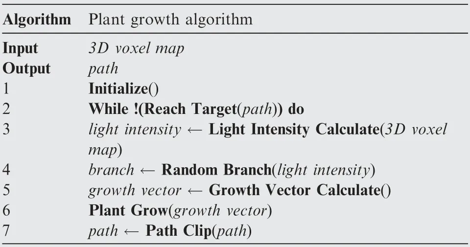
Table 1 Plant growth algorithm pseudocode.
2.3. Light intensity calculation
2.3.1. Coordinate transformation
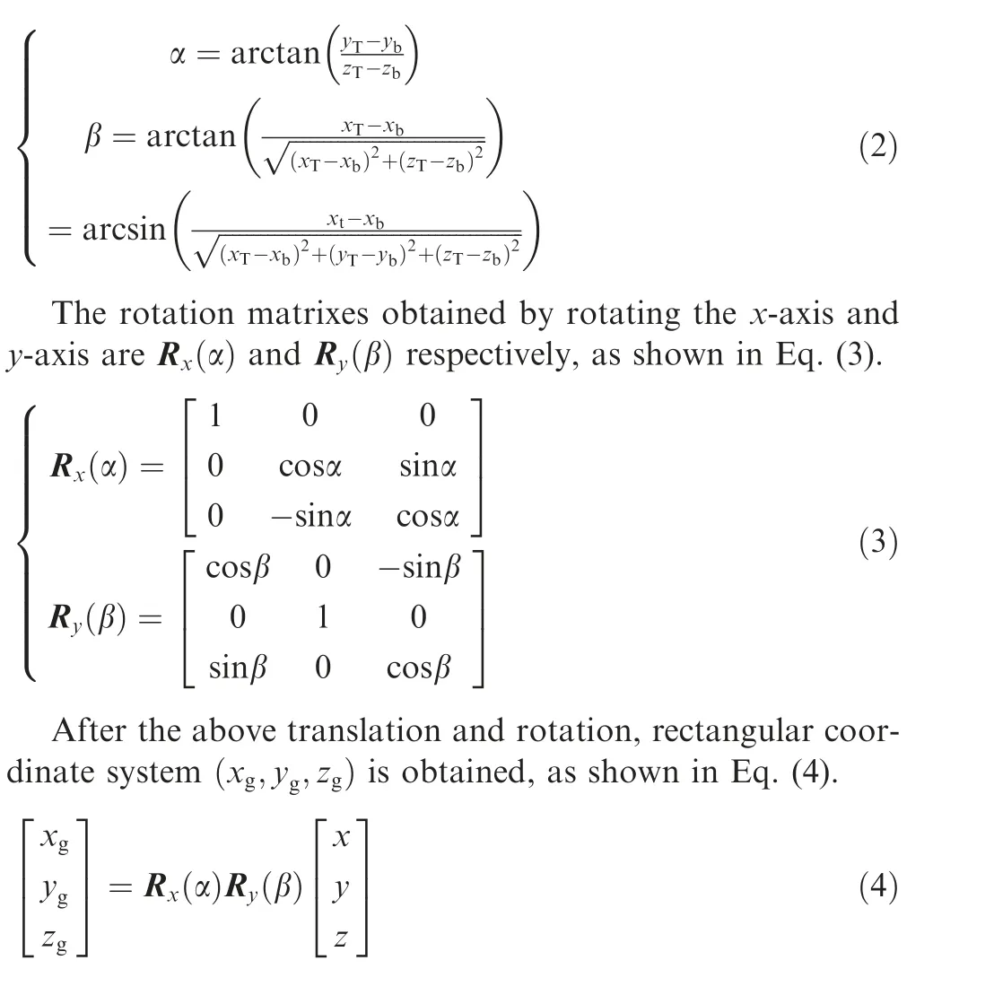
To simplify the calculation of the light intensity parameters of buds, the current bud is used as the origin, and the line between the bud and the target is represented by the rectangular coordinate in the z-axis direction.First,translate rectangular coordinates(x,y,z), as shown in Eq.(1), and obtain(x,y,z).

Then, for the translated rectangular coordinates,(x,y,z) rotates along the x-axis and y-axis respectively,Orthogonal coordinate system (x,y,z), where the direction of the line between bud (x,y,z) and target (x,y,z) is the z-axis direction, is obtained, The rotation angels around the x-axis and y-axis are αand β respectively, It can be obtained from Eq. (2).
2.3.2. Initial light intensity calculation
The definitions of ‘‘map resolution” and ‘‘search range” are given here. According to the principle of Octomap, the threedimensional map of space can be compressed and simplified by the principle of Octree, and become a space composed of a three-dimensional grid. The so-called ‘‘map resolution”refers to the grid size in the three-dimensional grid map.When the ‘‘map resolution” is high, the grid is small and the map description is detailed; when the resolution is low, the grid is large, and the map description is rough.

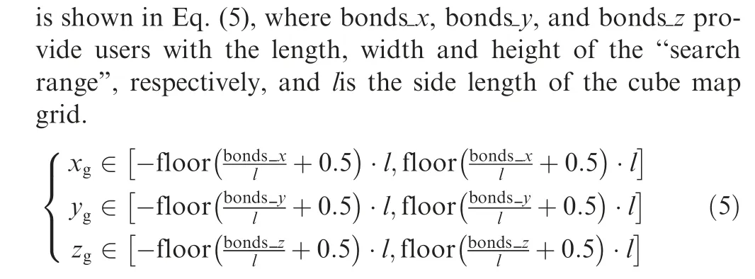
Calculate the initial light intensity of all grids in the search range (that is, the light intensity without considering occlusion). Assuming that the light intensity is inversely proportional to the square of the light source distance, to eliminate the light intensity difference caused by the change in the distance between the bud and to the target point and avoid the unreasonable and gradual increase in the light intensity in the later growth period, the calculation formula for defining the initial light intensity is shown in Eq. (6).

L(x,y,z) is the initial light intensity, Kis the light intensity coefficient, (x,y,z) are the coordinates of the current bud, and (x,y,z) are the coordinates of the target point.
2.3.3. Light intensity distribution calculation
The light intensity distribution is represented by discretization,and the reference ‘‘search range” is divided into a cube grid.The grid range of each discrete cube Ωis shown in Eq. (7).
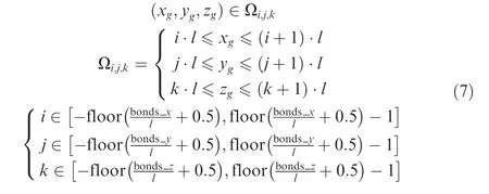
The total light intensity, Lisum, of the cube grid is the sum of the light intensity values of each point in Ω,as shown in Eq. (8).The equation is given as a reference for further calculations of the light intensity growth vector.

2.3.4. Grid light intensity calculation considering obstacles
If the grid searched in the ‘‘search range” is an obstacle or plant body,then the total light intensity, Lisum,of the grid is directly set to zero,which means no light passes through the grid. In addition, if part of the grid contains some obstacles,the total light intensity of the grid will be weakened. All grids in the search range are judged to be blocked by obstacles,and the actual total grid light intensity, Linew, considering the obstacles is obtained. The calculation process is shown in Eq. (9).

In the above formula,Linewis the total light intensity of the actual grid considering the obstacles, and Lisumis the total light intensity of the initial grid. l is the side length of the cube grid, and v is the volume occupied by obstacles or plants in the grid.
2.4. Random branch
We have determined the light intensity of the starting point and the ending point of the path, as well as the search range of the map. According to the principle, it needs to continuously grow towards the target point. However, it should be noted that due to obstacles, if we let the tree shape extend towards the target point, it may fail due to ‘‘hitting the wall”.Therefore,we adopt a random sampling method to choose the direction of the new buds according to the probability method.First, the calculation method of branch age is defined. The branching age of new buds is 1. Next, when the cell divides once, the branching age of a bud is increased by 1 until new branches are generated, and the branching age of a bud is set to 1 again. When the branching age of a bud satisfies Eq.
(10), branching probability P-is used to determine whether the bud branches. Ageis the cell age, and Age-is the branching age.

2.5. Growth vector calculation
2.5.1. Light intensity growth vector
After branch judgment, branch direction selection is needed.Branch direction candidate grid Ωis the cube grid within the search range, and satisfies Eq. (7).
Eq. (11) is used to calculate branch direction probability Pof branch direction candidate grid Ω, where Linewrepresents the total actual light intensity of candidate grid Ωin the branch direction, and ∑Linewrepresents the total light intensity of all grids in the search range.

According to the random branching rule, when branching probability P-is used to judge the need for branching,the direction of branching is random according to branching probability P. It can be seen from Eq.(11) that the centroid of the grid with strong total light intensity is more likely to be the endpoint of the next random branch direction.
After random branching, a grid centroid P(x,y,z) is selected as the light intensity growth node. The direction of light intensity growth vector Gis the random branch direction, that is, the direction of (x,y,z) of the grid centroid is selected by current bud end P(x,y,z) pointing to a random branch, as shown in Eq.(12).

2.5.2. Escape intensity growth vector

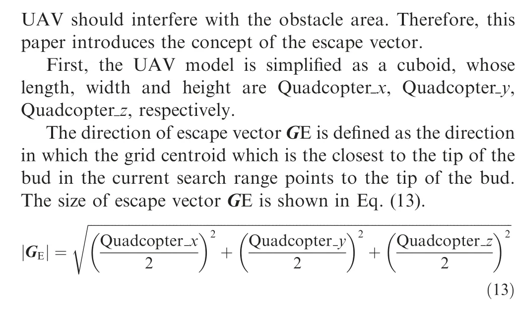
2.5.3. Gravity intensity growth vector
Gravity vector Gcan be obtained by connecting the starting point and the target point, as shown in Eq. (14).

2.5.4. Sum of vectors

The growth vector direction vector Gis obtained by the weighted sum of the above vectors, as shown in Eq. (15).where Gis the new growth vector direction vector,Gis the light intensity growth vector,Gis the escape vector,Gis the gravity vector,Gis the original growth vector,K,K,Kand Kare the weighting coefficients.
The concept of‘‘step length”is introduced here.Every time a plant’s new bud grows, it has a fixed step length. This step setting obviously also affects the shape of the tree. When the step size is too large, it may be too clumsy to successfully bypass the obstacles; when the step size is too small, the growth speed will obviously slow down(because the same distance needs to grow more times).Generally,the more complex the space is, the smaller the step size.
Finally, plant growth vector Gis obtained, its direction is the direction of vector G,and its size is shown in Eq.(16),where Range represents the step size.

2.6. Plant growth
The growth of plants is realized by bud cell division; that is,each bud is divided several times by the direction and size of the growth vector.Plant growth is carried out in the map rectangular coordinate system. First, (x,y,z), the growth vector endpoint in the translated and rotated bud rectangular coordinate system, is transformed into(x,y,z), the growth node in the map rectangular coordinate system, and the transformation relationship is shown in Eq. (17).

To prevent the growth path or interference between the UAV body and the obstacles, the dead bud conditions are defined here, as shown in Eq. (18) and Eq. (19). In Eq. (18)
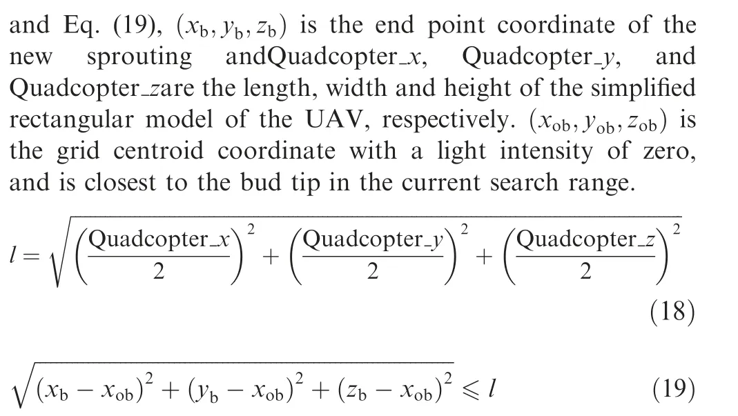
If the growth of the bud meets the conditions of the dead bud, it is proven that the path of this growth may lead to the collision between the UAV and obstacles, and this path is invalid. The bud is dead bud. After the bud withers, it is no longer calculated, and the node will be deleted from the plant growth path.
The criterion for judging the success of path generation is that the distance between the latest bud tip coordinate(x,y,z), and destination (x,y,z) is less than the threshold,Distance. That is, when the condition of Eq.(20) is satisfied, the path planning is considered to be successful and the planning result is output.

2.7. Path clipping
After outputting the planned path, we need to simplify the path. The original path generated by the algorithm consists of a series of waypoints, and the step size of the waypoints is the default value. If a UAV flies according to the path with the default step size, the flight task will be too cumbersome and the flight time will be too long, so we need to delete the extra and unimportant waypoints in the path.
The judgment conditions are given as follows: for a path from point A to point B, if any two points are collinear, only the beginning and end points of the path will be reserved, and the middle part will be deleted, as shown in Fig. 1.
In the picture,the blue rectangle represents the obstacle;the path composed of red dots represents an original path, in which there are many additional waypoints; the path composed of green dots is the path after collinear judgment on the original path, in which only the points at the corner are reserved.

Fig. 1 Path clipping diagram.
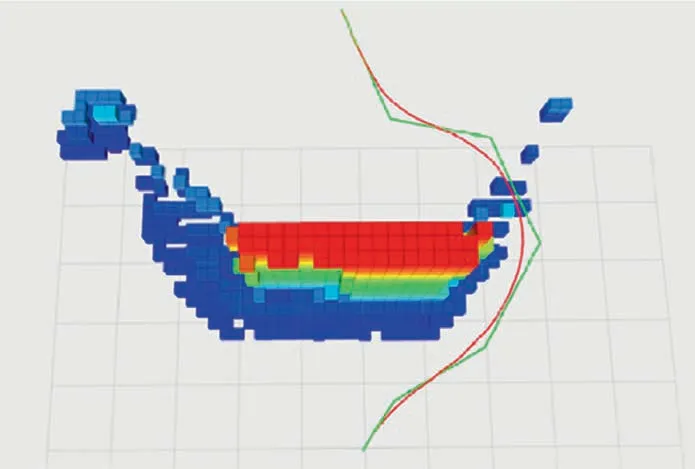
Fig. 2 Path optimizing.
2.8. Path optimizing
If the waypoints are directly connected into a broken line, as shown in the green line in Fig. 2, the UAV will suddenly change its direction in flight, and the maneuverability of the aircraft may not meet the command of sudden direction change.
Therefore, considering the turning radius and maneuverability limitation of the aircraft, the B-spline curve optimization is carried out for the waypoints generated by the algorithm,and a smooth curve is obtained as the UAV mission route, as shown in the red line in Fig. 2. Different UAVs will generate corresponding spline curves according to their maneuverability characteristics.
3. Experimental verification
The program implementation of the algorithm is based on the ROS platform.A UAV uses a stereo depth sensor to obtain the point cloud information of the obstacles. After a series of filtering processes,the point cloud is transformed into an Octree map. A user sends destination information to the UAV. In combination with the location information and map information of a UAV, the UAV uses the algorithm to generate the planned path, and flies along the path to complete the task.The structure of the program is shown in Fig. 3.
In this section,simulation subjects and actual experimental subjects are designed to verify the abovementioned autonomous obstacle avoidance path planning algorithm. Using the Gazebo simulator based on the ROS platform to build the simulation environment test algorithm software system, the plant growth algorithm is compared with other path planning algorithms. Then, the algorithm software system is imported into the airborne computer, compiled and ran, tested in the actual situation,and compared with the simulation and the actual situation of the path planning of the plant growth algorithm and the flight situation of the aircraft.
The operation process of the plant growth path planning algorithm in an autonomous obstacle avoidance path planning UAV system is as follows: first, the obstacle point cloud data are obtained by an obstacle sensor such as a depth camera,and then the 3D Octree map is generated after point cloud filtering and coordinate transformation. After obtaining the local location and destination of the aircraft through the positioning system and network, the plant growth path planning algorithm will receive the environment map, aircraft location and destination coordinates, and plan the path for aircraft navigation in real time.
Compared with the traditional algorithm, this algorithm optimizes an actual UAV mission flight.Compared with other biologically inspired algorithms, it uses the characteristics of phototropism and negative geotropism to guide the optimization direction rather than the objective function. In this way,only the value of the next waypoint needs to be optimized at each step, as opposed to determining the objective function of all waypoints. Therefore, this method reduces the complexity and improves the computational efficiency.
3.1. Simulation experiments
In this paper, we first create an environment in the Gazebo simulator to imitate brick wall obstacles and carry out a path planning comparison experiment to compare the plant growth algorithm, the A* algorithm, the RRT algorithm and the ant colony algorithm. In this environment, there are brick wall obstacles with lengths, widths and heights of 7 m, 1 m and 3 m, respectively, in the (0,4,0) position, and the brick wall is an obstacle that needs to be avoided in the actual flight simulation. The starting point of the planned path planning is at(0,0,1.2), the ending point of the planned path planning is at(8,0,1.2), and the coordinate system unit is m. The simulation environment of the Gazebo brick wall obstacles is shown in Fig. 4.
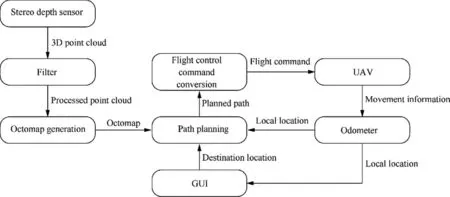
Fig. 3 Program structure diagram.
In addition to rectangular obstacles such as brick walls, an obstacle avoidance test of a cylinder(similar to a lamp post)is also carried out, as shown in Fig. 5. The simulation and comparison experiments are carried out when there are lamp post obstacles with heights of 2.5 m and radii of 0.2 m at the(0,3,0)position on the map.The starting point of the planned path is at (0,0,1.2), and the end point of the planned path is at(8,0,1.2), and the coordinate system unit is m.
In this paper, the plant growth algorithm, A* algorithm,RRT algorithm and ant colony algorithm are used to plan the path simultaneously in two typical obstacle environments,and the results are compared and analyzed.
Fig. 6 shows the brick wall obstacle avoidance environment. Under the same starting point and ending point, the comparison diagram of the planned paths of the four algorithms are shown. Fig. 7 and Fig. 8 show the comparison of the panned paths of four algorithms under the same starting point and ending point in the lamp post obstacle avoidance environment.Table 1 and Table 2 show the specific parameter differences among these four algorithms.
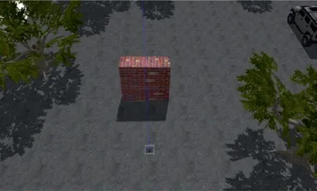
Fig. 4 Brick wall obstacle avoidance simulation environment.
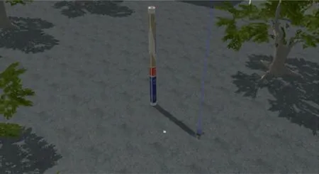
Fig. 5 Lamp post obstacle avoidance simulation environment.
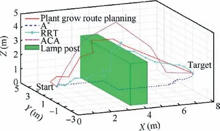
Fig. 6 Paths of four algorithms for brick wall obstacle avoidance.
As shown in Figs. 6, 7 and 8, the red solid line represents the route planned by the plant growth algorithm,the blue dotted line represents the route planned by the A* algorithm, the blue dot solid line represents the route planned by the RRT algorithm, and the purple dotted line indicates the route planned by the ant colony algorithm. All four algorithms can plan an effective path. The path generated by the plant growth algorithm and the A*algorithm are relatively smooth,while the paths planned by the ant colony algorithm and RRT algorithm are more tortuous. This is because the ant colony algorithm is a typical probability algorithm,and the parameter setting in the algorithm is usually determined by the experimental method, resulting in the optimization performance of the method being closely related to human experience; hence,it is difficult to optimize the performance of the algorithm.The principle of the RRT algorithm is to search for a planning path from the starting point to the target point through the randomly sampled points in the state space,to find a path plan from the starting point to the target point. Although the method can find the successful path, due to the randomness of the sampling process, the quality of the path is poor.
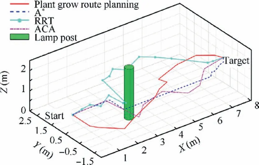
Fig. 7 Paths of the four algorithms for lamp post obstacle avoidance.
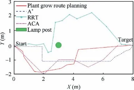
Fig.8 Top view of path comparison among the four algorithms.

Table 2 Parameters for brick wall obstacle avoidance.

Table 3 Parameters for lamp post obstacle avoidance.
The parameters of the specific path planning process are shown in Table 2 and Table 3.The planning times of the plant growth algorithm and RRT algorithm are one order of magnitude lower than those of the A* algorithm and ant colony algorithm. This is because plant growth is a step-by-step path planning algorithm. It only needs to calculate the growth direction of each iteration and the growth amount of the next step,and the calculation amount is small.However,RRT uses a random growth mode, so the calculation is very small and the speed is the fastest.The spatial growth of the A*algorithm is exponential, and it takes the longest among all algorithms.In theory,the ant colony algorithm requires all ants to choose the same route, which is the optimal route. However, in the actual calculation, it is difficult to achieve this situation under the condition of a certain number of cycles, resulting in slow convergence speed of the algorithm and no optimal solution.In addition,by observing the length of the path,it can be seen that the plant growth algorithm path length is slightly longer than the path length of the A* algorithm, but shorter than the path of the RRT algorithm. Comparing the time differences in the two different scenarios, it is found that the time consumption of the plant growth algorithm is almost the same,while the time consumptions of the A* algorithm and ant colony algorithm are significantly different. This shows that the plant growth algorithm has strong adaptability.It is more suitable for a dynamic environment with changing scenes.
In conclusion, compared with the A* algorithm and ant colony algorithm, the plant growth algorithm has faster planning speed and stronger adaptability to dynamic obstacle environments. Compared with the RRT algorithm, although the speed of the plant growth algorithm is slightly slower,the generated path is smoother and the length is shorter.
3.2. Real obstacle avoidance path planning experiments
Build an experimental platform for the autonomous obstacle avoidance path planning of UAVs, and test the performance of the system in the actual environments with the above algorithm. The structure of the experimental platform is shown in Fig. 9, and the physical figure of the experimental platform is shown in Fig. 10.
The plant growth algorithm is applied to the UAV autonomous obstacle avoidance path planning platform shown in Fig. 10, and the experiment is carried out in the environment shown in Fig. 11. The obstacle scene is as follows: there are pedestrian like obstacles with lengths, widths and heights of 0.5 m, 0.6 m and 1.8 m, respectively, at the (2,0,0) position.The starting point of the planned path is(0,0,1.2),the ending point of the planned path is(6,0,1.2),and the coordinate system unit is m.In the case of the same obstacle shape and starting point and ending point, the simulation and actual flight contrast experiments are carried out, and the experimental results are shown in Figs. 12, 13 and Table 4.
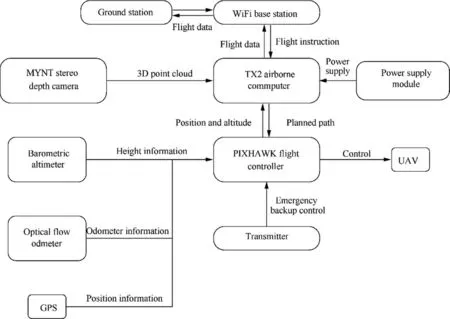
Fig. 9 Hardware system structure diagram.

Fig. 10 Finished hardware system drawing.
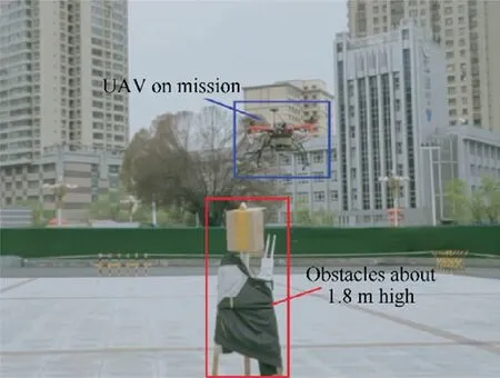
Fig. 11 Actual experiment diagram.
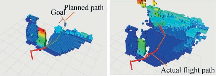
Fig. 12 Simulation experiment results.
Fig. 12 shows the algorithm planning path and the actual flight path of the aircraft in the simulation environment, and Fig.13 shows the algorithm planning path and the actual flight path of the aircraft in the actual environment.In the figure,the green thin line represents the algorithm planning path,and the red thick line represents the actual flight path of the aircraft.It can be seen that the aircraft can successfully reach the destination by bypassing obstacles along the path planned with the algorithm,but the flight path is slightly different from the path planned by the algorithm.The reason for the difference is,considering the limited computing power of the airborne computer and the flight control system, that the algorithm simplifies the whole path into waypoint data and sends it to the aircraft,and the aircraft flying to the waypoint will be affected by external disturbances, resulting in a small range of deviation.
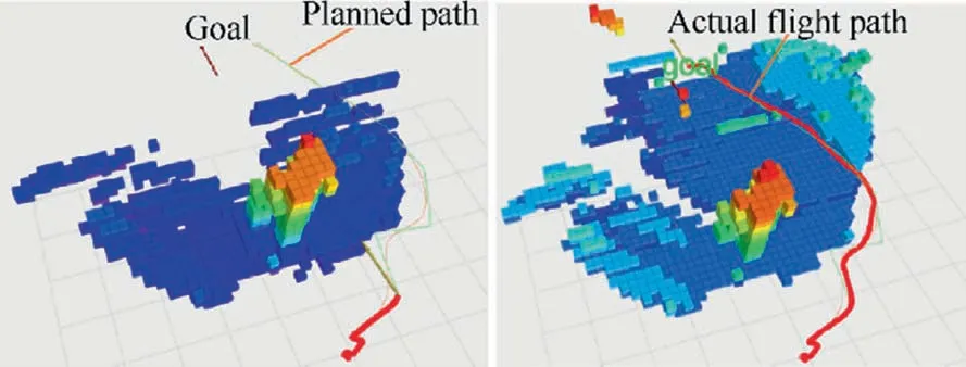
Fig. 13 Actual experimental results.
It can be seen from the comparison results in Table 4, that under the same obstacle environment and planned starting and ending points, the number of waypoints and planned path length of the simulation and actual experimental algorithm are not significantly different, however, the mission flight time in the actual experiment in slightly slower than that in the simulation environment. It is speculated that this difference is caused by wind interference in the outdoor environment, and PIXHAWK uses a barometer to calculate the aircraft height.When there is wind,the barometer detection results will be disturbed,resulting in errors in the measurement of local aircraft height information.In addition,when the flight altitude of the optical flow sensor is greatly disturbed, there will be errors in the measurement of aircraft mileage, which will affect the speed of the final mission.
To further verify the feasibility of the proposed path planning algorithm, an indoor compound obstacle avoidance experiment is added after the simple obstacle scene experiment.The obstacle scene is shown in Fig. 14.
As shown in Fig. 14, the site is 13 m long and 12 m wide,and there are two gates at the diagonal position. There are cylinder obstacles with diameters of 0.15 m,rectangular obstacles with lengths of 3 m and widths of 2 m, and door plate obstacles with widths of 2 m.The UAV needs to enter through the entrance door,bypass all obstacles and fly out from the exit door. Finally, the UAV mission flight path using the plant growth algorithm is shown in the red trajectory of Fig. 15.
Through the actual complex obstacle experiment, the efficiency of the plant growth algorithm is well verified.The environment is completely unknown to the aircraft before the mission.In flight,the binocular depth camera is used to detect obstacles,and then map and plan the path in real time to complete the mission. Due to the real-time mapping, the map is dynamic and frequently changing.The algorithm needs to plana new flight path for the aircraft according to the moving aircraft orientation, destination location and dynamic map. In the actual experiment, after turning on the high-performance mode of the TX2 airborne computer, the algorithm achieves an update frequency of 1 Hz, and updates the planning path according to changes in the external environment. In the contrast experiment, the A* algorithm and ant colony algorithm are not competent for the ever-changing environment map and aircraft location,resulting in aircraft crashes,The fluctuations in the planned path of the RRT algorithm are too large and, the aircraft performance is limited and cannot be completed.

Table 4 Comparison of simulation and actual experimental results.
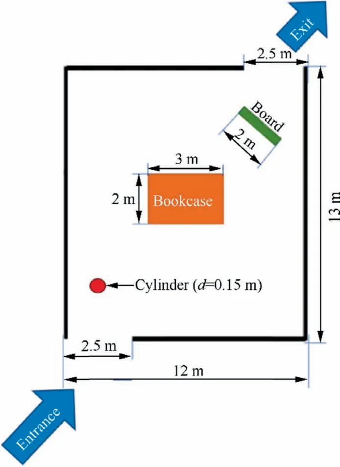
Fig. 14 Composite obstacle map.
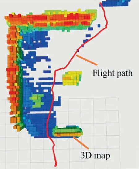
Fig. 15 Actual experimental results.
4. Conclusions
In this paper,a path planning method for plant growth is proposed. Based on the characteristics of full use of sunlight in plant growth, the method uses the basic physiological mechanism of plant backwardness,phototropism,branching and apical advantages to model and design algorithms, and achieves the ability of path planning from the starting point to the target point to avoid all obstacles.
In this paper, the plant growth algorithm and a UAV are combined to realize autonomous obstacle avoidance path planning considering the flight performance of UAVs and the processing ability of airborne sensors and computers. In the algorithm, the in-flight obstacle information is collected by a stereo depth sensor and converted into point cloud data.After processing and simplification, a three-dimensional map of an obstacle is established by using the Octree mapping principle.Finally,according to the three-dimensional map,a route is planned by using the proposed plant like growth path planning method, and a UAV is controlled to avoid obstacles and reach the destination.
Compared with the A* algorithm, RRT algorithm and ant colony algorithm,the results show that the plant growth algorithm has good path planning ability and reasonable parameter configuration.The operation efficiency of the plant growth algorithm is high, and the operation process is stable. In the actual mission flight test, the advantages of the algorithm are also verified, and dynamic obstacle avoidance path planning in a complex environment is realized.The application of plant growth algorithms in other optimization problems will be a necessary and interesting research direction.
Declaration of Competing Interest
The authors declare that they have no known competing financial interests or personal relationships that could have appeared to influence the work reported in this paper.
Acknowledgements
The authors gratefully acknowledge the support of the Zhejiang Lab (No. 2019NB0AB04), National Natural Science Foundation of China (No. 61903014), Aeronautical Science Foundation of China (No. 20181751010) and Fundamental Research Funds for the Central Universities, China.
 CHINESE JOURNAL OF AERONAUTICS2021年9期
- CHINESE JOURNAL OF AERONAUTICS的其它文章
- Optimal trajectory and downlink power control for multi-type UAV aerial base stations
- Effects of flow parameters on thermal performance of an inner-liner anti-icing system with jets impingement heat transfer
- Effects of wing flexibility on aerodynamic performance of an aircraft model
- Aerodynamic performance enhancement of co-flow jet airfoil with simple high-lift device
- Adaptive fuzzy terminal sliding mode control for the free-floating space manipulator with free-swinging joint failure
- Influence of longitudinal-torsional ultrasonicassisted vibration on micro-hole drilling Ti-6Al-4V
