Novel design and simulation of curved blade oil scoop with high oil capture efficiency
Jingwen QIN,Hui GUO,Huiqing JIANG,Fuling WANG,Weiwei MAN,Yguo LYU
a School of Mechanical and Electrical Engineering, Central South University, Changsha 410083, China
b AECC Hunan Aviation Powerplant Research Institute, Zhuzhou 412002, China
c School of Power and Energy, Northwestern Polytechnical University, Xi’an 710129, China
KEYWORDS Bearing;Capture efficiency;Numerical simulation;Oil scoop;Under-race lubrication
Abstract As the load and working environment temperature increasing,high efficiency oil lubrication was urgently needed for the main bearing of aeroengine.However,the low oil capture efficiency of radial oil scoop affects the application of under-race lubrication structure with radial oil collection.In this work,a novel design of curved blade oil scoop for under-race lubrication is proposed to improve the oil capture efficiency.First of all,the principle of relative velocity optimization is proposed by analyzing the collision process between blade and oil jet for theoretical research.Then,the theoretical curve equations of blade inlet under three different oil jet incidence conditions are solved. After that, the monotonicity of the theoretical curves is analyzed. The effects of rotation speed,oil jet velocity,eccentric distance of oil jet,and include angle of curve are analyzed.The location of the collision points of proposed theoretical curves are also been optimized. Finally, a transient Computational Fluid Dynamics (CFD) simulation of the novel oil scoop design was carried out. The simulation results show that the capture efficiency of curved blade oil scoop can be improved by 30% comparing to the traditional design.
1. Introduction
As the high speed, heavy load and high working environment temperature demand of the main bearing of aeroengine, high efficiency oil lubrication was widely used to lubricate and cool the rollers, inner rings, outer rings and cages of bearings.According to the different lubrication methods of bearings,they are usually divided into spray lubrication and underrace lubrication.With the requirements of high speed and high power to weight ratio of modern aeroengine,the DN(product of bearing inner diameter and rotation speed) value of main bearing is also higher and higher.For high DN value bearings,if the traditional spray lubrication is used,the lubricating oil is difficult to enter the high-speed rotating main bearing under the action of centrifugal force, resulting in the unsatisfactory lubrication and cooling effect.
In order to meet the needs of high DN value bearing lubrication and cooling, the main bearing of modern advanced aeroengine usually adopts the way of under-race lubrication which supplies oil from the bottom of inner ring to the bearing.In under-race lubrication,the lubricating oil in the inner ring of the bearing rotates with the high speed of the bearing.Under the action of centrifugal force,the lubricating oil enters into the bearing through the radial hole on the inner ring to lubricate and cool the friction pairs of bearing. For high DN value bearing, the lubricating oil is easier to enter into the bearing for effective lubrication and cooling. Compared with spray lubrication, when under-race lubrication is used, the oil supply is less, the stirring heat generated by the oil is smaller, and the heating condition of the bearing is improved.Therefore, under-race lubrication is very beneficial to prolong the service life of aeroengine main bearingand to reduce the circulating flow of aeroengine oil system.
For the under-race lubrication mode, the lubricating oil sprayed by the nozzle (hereinafter referred to as the oil jet)needs to be collected through the oil collecting structure and then supplied to the bearing inner ring. According to the different ways of oil collection,it can be divided into axial oil collection and radial oil collection. Axial oil collection refers to that the oil sprayed by the nozzle is collected through the oil retaining dam set axially,as shown in Fig.1.Radial oil collection usually refers to that after passing through the nozzle,the oil is ejected along the plane perpendicular to the main shaft, and then captured through the radial oil scoop,as shown in Fig. 2. The radial oil collecting structure is suitable for the condition that the axial space of the engine bearing chamber is not sufficient. It can supply oil under the ring of the main bearing without increasing the inner diameter of the bearing, which is very beneficial to improve the reliability of the main bearing.

Fig. 1 Axial oil collection structure.

Fig. 2 Radial oil collection structure.
Limited by the structure of under-race lubrication and the space of bearing cavity, it is impossible for the oil sprayed by the nozzle to supply to the inner ring of the bearing completely, and there is always a part of splash, reflection and loss.In under-race lubrication,the ratio of the oil supplied to the inner ring of the bearing and the oil supplied by the nozzle is called the oil supply efficiency. Generally speaking, the oil supply efficiency of under-race lubrication for axial collection structure is more than 90%, even close to 100%. The oil supply efficiency of under-race lubrication for radial collection structure is closely related to the structure of the radial oil scoop,the diameter and arrangement of the nozzle,the oil supply pressure and the oil supply temperature.According to the relevant literature, the oil supply efficiency is 50%–80%generally.
The radial oil scoop is the key of the radial oil collection structure, which plays an important role in the oil supply efficiency of the under-race lubrication structure.
The concept of radial oil scoop is not new. In 1967, Pabst and Silayproposed the concept of early radial oil scoop with blade and fence structure. Kovaleskiproposed a double side oil supply structure with radial oil scoop. The oil is captured by radial oil scoop and supplied to the lubrication points on both sides of scoop, and the distribution of oil is controlled through the axial passage.Fisherobtains different oil supply ratios on both sides by changing the blade angle of radial oil scoop. Based on the assumption of the relative velocity of oil relative to the blade, Dins et al.proposed a kind of curved blade oil scoop to improve the oil capture efficiency.The curve of the inner surface of the blade is defined as an exponential function.
The early design of radial oil scoop mainly depends on experience, and the Computational Fluid Dynamics (CFD)and theoretical research starts late. The Volume of Fluid(VOF) method has been used to establish the transient CFD model of radial oil scoop in FLUENT software, and Prasad et al.studied the influence of shaft speed, oil flow, width and outer diameter of oil scoop efficiency. Lyu et al.used the VOF two-phase flow model to simulate the oil collecting process of the radial oil scoop, and obtained the oil capture efficiency under the conditions of different rotating speed, oil supply flow and nozzle number.Korsukova et al.established CFD and Smoothed Particles Hydrodynamics (SPH) models in the process of oil collection.
At present,most of the patents,simulation and experimental research on radial oil scoop are traditional scoop structure with straight blade inlet.Because there are many parameters that affect the oil scoop capture efficiency, the blades of traditional scoop are usually designed based on experience.In order to achieve higher oil capture efficiency,it is necessary to design different schemes of scoop structure, which takes a lot of time for simulation calculation, and takes a longer time if the experimental method is used. Therefore, there is an urgent need for a rational blade design method of radial oil scoop, which can quickly obtain the structure with high oil capture efficiency.
2. Working principle of radial oil scoop
The typical radial oil scoops are shown in Fig.3,where ω is the rotation speed of scoop. Scoops usually composed of several blades.

Fig. 3 Structure of traditional oil scoop.
Oil scoop is usually mounted on a shaft. When the shaft rotates, the scoop rotates with the shaft to capture and transport oil. The oil nozzle injects oil along the center of shaft (or at a distance from the center of shaft). When the oil scoop rotates in the direction shown in Fig. 3(a), the oil jet is captured by the blade into the capture cavity inside the blade.As shown in Fig. 3(a), the oil scoop is composed of three blades,and each blade consists of inner surface and outer surface.Taking the throat as a boundary,the inner surface of the blade is divided into two parts: the blade inlet and the blade cavity. The enlarged view of the throat is shown in Fig. 3(b),where ris the radius of throat,ris the outer radius of capture cavity.The outer radius of capture cavity is slightly larger than the radius of throat, that is r> r.
When the scoop is rotating at high speed, oil will attach to the outer wall of capture cavity under the action of centrifugal force. Because the inner diameter of throat is smaller than the outer diameter of the whole oil transportation channel, the centrifugal potential energy at the throat is low, and the centrifugal potential energy at the oil transportation channel is high. Therefore, the oil in the capture cavity is not easy to cause secondary outflow through the throat. Under the action of centrifugal force,the lubricating oil in the oil delivery channel enters the inner ring of the bearing, passes through the axial grooves and radial holes on the inner ring of bearing,and then throws out from the surface of the raceway, so as to realize the oil supply from the bottom of inner ring to the bearing.
Therefore,the blade is the key structure of radial oil scoop.The blade inlet and blade cavity on the inner surface of the blade have great influence on oil capture and transportation.

Fig. 4 Collision process between oil jet and blade.
The detailed collision processes between the oil jet and the blade inlet are shown in Fig.4.Due to the high rotation speed of the radial oil scoop,the speed of blade is far greater than the oil jet speed.Thus,the oil jet is approximately considered to be stationary at the moment of collision. As shown in Fig. 4(a),the tip of blade contacts with the oil jet and starts to ‘‘cut”the oil jet. Then the blade gradually contacts with the oil jet in the order from the outside to the inside, as shown in Fig.4(b).Finally,as shown in Fig.4(c),the oil jet is completely attached to the inner surface of blade inlet under the inertial action, and rotates with the blade of scoop.
At the moment when any oil micro element in the oil jet collides with the blade inlet,the motion state relative to the rotating blade is shown in Fig. 4(d). The blade velocity Vat the position where the micro element is located can be expressed as V= ωr, where ω is angular velocity, and r is the radius of the micro element relative to the center of shaft.
According to the velocity composition theorem,the velocity of the micro element in the relative rotating coordinate system V is defined as

where Vis the absolute velocity of the micro element,and is equal to the velocity of oil jet; Vis the blade velocity.
Therefore, the relative velocity between the oil micro element and the blade is shown in Fig.4(d). The relative velocity direction is opposite to the absolute movement direction of the blade, and points to the capture cavity of scoop. Under the action of the inertial force generated by the relative velocity,the oil micro element will flow to the capture cavity. Since the relative movement trend is applicable to any oil micro element on the blade inlet, the oil will flow along the blade wall and flow into the capture cavity finally,so as to capture the oil.
3. Curve design of blade inlet
3.1. Principle
Obviously, when the velocity V of the oil micro element relative to the blade at the collision point is located in the tangent direction of blade inlet, the oil micro element is most easily captured,and the oil capture efficiency of the scoop is the highest. When the blade inlet is a straight line as shown in Fig. 3,with the position change of collision point,the relative velocity of the oil micro element will change,and the direction of relative velocity at the collision point will also change. So for the blade inlet with a straight line, it is impossible to ensure that the relative velocity of oil micro element at the collision point is always in the tangent direction of blade inlet. If the vector direction of the velocity in the relative coordinate system of the point where any infinitesimal body is located is in the tangent direction, the entrance of the inner surface of the blade should be designed as a specific curve shape. If the relative velocity vector direction of oil micro element at any collision point is always in the tangent direction of blade inlet, the surface of blade inlet should be designed as a specific curve shape.
When the shape of the blade inlet is a curve,and the relative velocity V of the oil at the collision point P is located in the tangent direction of the curve on the blade inlet,the oil is most easily captured and the oil capture efficiency of the blade is the highest. The following assumptions are made for the oil collecting process of the radial oil scoop to solve the corresponding internal surface curve of the blade inlet.
(1) Ignoring the influence of nozzle diameter, the oil jet ejected from the nozzle is regarded as a straight line,which is collinear with the center line of nozzle.
(2) Ignoring the influence of wind resistance,it is considered that the oil jet always moves in a straight line, and the speed of oil jet remains unchanged.
(3) Since the nozzle is stationary, the distance between the center line of nozzle and the scoop center can be regarded as a constant.

3.2. Equation derivation


Fig. 5 Relationship between oil jet and scoop.

Fig. 6 Velocity synthesis of oil jet and blade (Case 1).


Fig. 7 Velocity synthesis of oil jet and blade (Case 2).

The relationship between the oil jet of nozzle and the rotation direction of the radial oil scoop is shown in Fig. 8.


Fig. 8 Velocity synthesis of oil jet and blade (Case 3).

Eq. (20) can be written as β = f(r), which gives the function of the inner surface curve of the blade inlet in Case 3. It can be considered that β = f(r) is a special case of functions β = f(r) and β = f(r) when d= 0.
4. Curve results and discussion
The structures of blade have great influence on the oil capture efficiency.For the derived blade curve equations Eqs.(14),(17)and (20), it is necessary to study the curve characteristics.Through the monotonicity analysis and parameter research,the influence trend of them on the radius is obtained, so as to select the appropriate radius value in the blade structure design and improve the capture efficiency of curved blade oil scoop. In addition, it is also important to study the collision point of oil jet and blade for the analysis of oil capture efficiency of scoop.
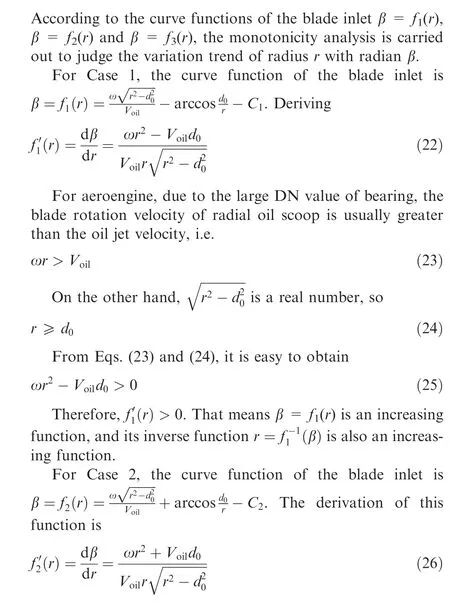
4.1. Monotonicity analysis

4.2. Parametric study
4.2.1. Curve results
According to the curve function of the blade inlet which was described in Subsection 3.2, the curve is obtained as shown in Fig. 9.
The radial oil scoop rotates anticlockwise around point O at angular velocity ω. Pis the initial point (start point) of the curve on the inner surface of the blade, and Pis the end point of the curve.
As shown in Eqs. (28) and (29), the include angle between the start point and the end point of the curve is defined as Δβ, and the radius change value of these two points is defined as Δr.Obviously, the polar radius rof the end point Pis larger than the polar radius rof the starting point P, so Δr > 0.

4.2.2. Effect of rotation speed
The rotation speed of the shaft is an important parameter for the theoretical curve.Fig.10 is the graph of the ratio Δr/r(radius change value Δr to initial value radius r)with the rotating speed change when d/r=1.In Case 1–Case 3,the ratio Δr/rdecreases with the increase of rotating speed. When the rotation speed is small, the ratio Δr/ris very large, and with the increase of the rotation speed, the ratio drops a lot.

Fig. 9 Curve results of blade inlet.
At the same rotation speed, the ratio Δr/rof Case 1 is always greater than Case 2, but with the increase of rotation speed, the difference between Case 1 and Case 2 gradually decreases and tends to be consistent. The change trend of Case 3 is similar to that of Case 1 and Case 2, but its ratio is larger at high speed, which is mainly determined by the eccentric distance of oil jet.
4.2.3. Effect of oil jet velocity
The oil jet velocity is closely related to the oil supply pressure of the aeroengine oil system.The common oil jet velocity of the aeroengine is generally 10–30 m/s. As shown in Fig. 11, the ratio Δr/rincreases with the increase of oil jet velocity in Case 1–Case 3. In other words, reducing the oil jet velocity is conducive to reducing the radius of the theoretical curve.
The influence of oil jet velocity in Case 1 is greater than that in Case 2, and the higher the oil jet velocity is, the more obvious the influence on radius change is.In Case 3,the ratio Δr/rincreases linearly with the oil jet velocity,and the slope can be expressed as Δβ/(ωr).
4.2.4. Effect of eccentric distance of oil jet
Eccentric distance of oil jet has great influence on the arrangement of oil nozzle for radial oil scoop. Fig. 12 shows that the relationship between radius increase coefficient and eccentric distance ratio for Case 1 and Case 2. When the eccentric distance ratio d/rapproaches 1.0,it decreases rapidly.For Case 3, it is actually a special case at d/r= 0 in Fig. 12. In this case, the nozzle shoots at the center of the shaft, and the two curves of Case 1 and Case 2 meet at the same point. Through the analysis of Fig.12,it can be obtained that when arranging the nozzle structure, larger eccentric distance can reduce the radius of the theoretical curve.
4.2.5. Effect of include angle of curve
The include angle Δβ as mentioned in Subsection 4.2.1 is an important structural parameter of theoretical curve design.According to the monotonicity analysis of Subsection 4.1,the radius r(β) of curve increases with the increase of radian β. Therefore, in Fig. 13, the ratio Δr/rincreases with the increase of include angle.

Fig. 10 Relationship between radius increment coefficient and rotation speed.

Fig. 11 Relationship between radius increment coefficient and oil jet velocity.

Fig. 12 Relationship between radius increment coefficient and eccentric distance ratio.
The influence of include angle on radius is similar to that of oil jet velocity. As shown in Fig. 13, the influence of include angle in Case 1 is greater than that in Case 2, and the larger the included angle is,the more obvious the influence on radius is.In Case 3,the ratio Δr/rincreases linearly with the include angle, and the slope can be expressed as V/(ωr).

Fig. 13 Relationship between radius increment coefficient and include angle of curve.
4.3. Collision point analysis

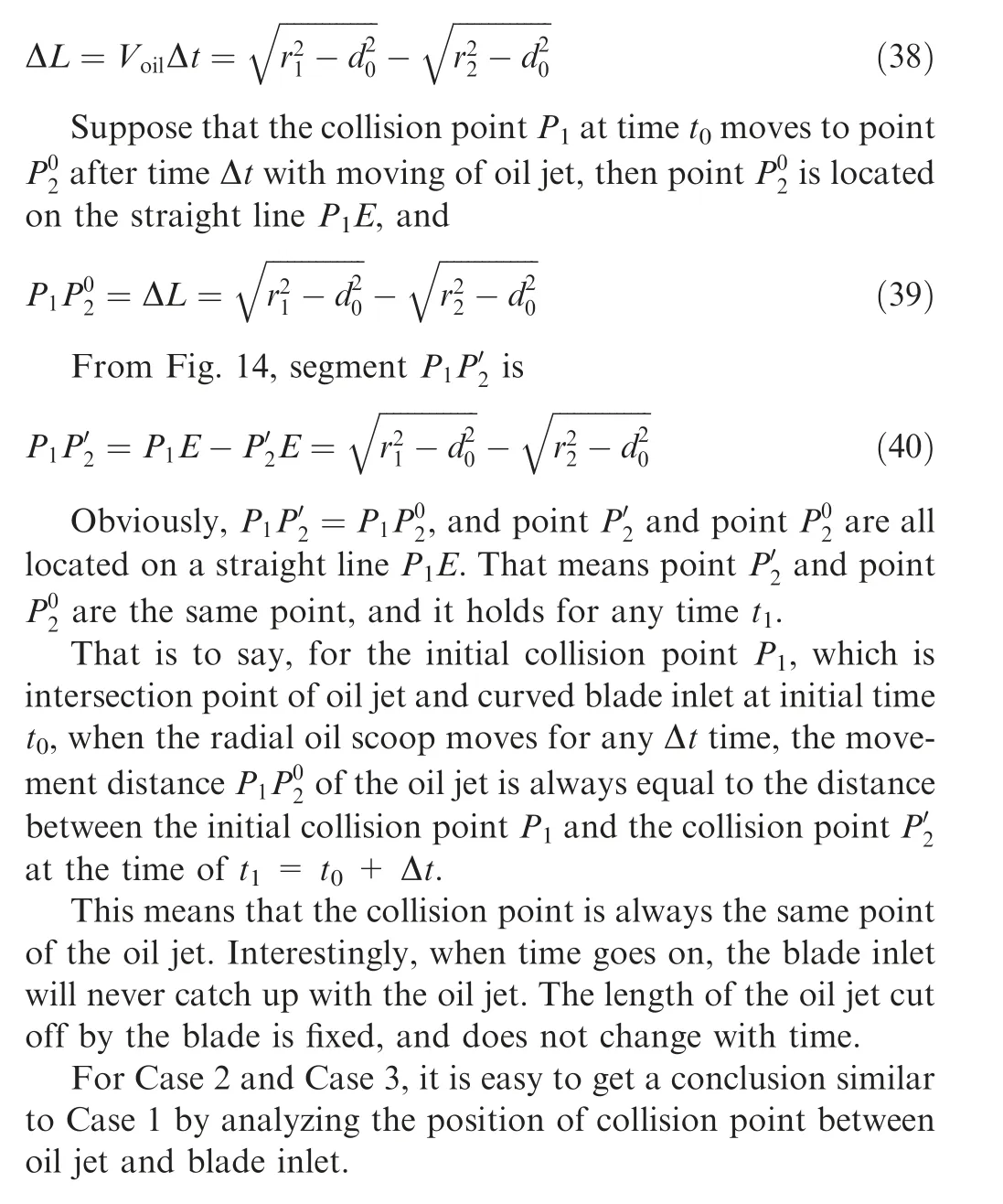
According to the assumptions in Subsection 3.1, the oil jet moves at a constant speed. So, its movement distance ΔL in time Δt becomes
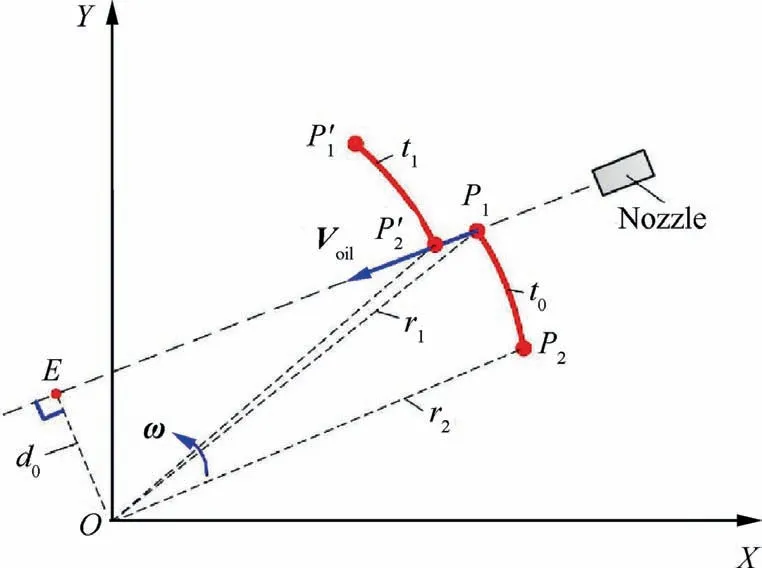
Fig. 14 Collision point of oil jet and blade (Case 1).
5. Simulation of oil capture efficiency
5.1. Geometry
According to the curve results in Subsection 4.2.1,the rational designed curved blade oil scoop is shown in Fig. 15. An oil nozzle is set up to supply oil, and the oil jet from the nozzle is directed towards the rotation direction of the oil scoop,which is the same as Case 2.The scoop has four curved blades to capture oil. Each blade inlet inner surface is based on the curve function which was described in Eq. (17), and the outer surface of blade is the offset of the inner surface.
5.2. Simulation configuration
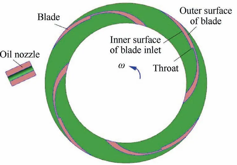
Fig. 15 Curved blade oil scoop with oil nozzle.

Fig. 16 Mesh of computational domain.
The oil collecting process of curved blade oil scoop is simplified as a two-dimensional model for calculation. As shown in Fig. 16, the calculation domain is divided into two parts: the internal rotating domain with oil scoop and the external stationary domain with oil nozzle. The outlet of the nozzle was set as velocity inlet boundary.At the outlet of internal rotating domain and the external stationary domain,both pressure outlet boundaries were used. Quadrilateral structured grids are used in both the stationary and rotating computational domains, and suitable resolutions of grids were selected.
The Sliding Mesh Model (SMM) was selected to calculate the rotation of oil scoop. And the realizable k–ε turbulence model was used to solve the fluid flow of complex scoop structure.The oil collecting process of scoop is a typical two-phase flow,the interface between oil and air can be well captured by VOF method.
5.3. Simulation results
FLUENT is used to calculate the transient process of oil capture,and the simulation results is shown in Fig.17(a).The product of shaft diameter and rotation speed of oil scoop is about 1.75×10mm·r/min.Through the contour of oil volume fraction, it can be seen that after using curved blade, the splashed and choked oil is less compared to traditional blade (Fig. 17(b)),which is conducive to improving the oil capture efficiency.The oil capture efficiency η is defined as the ratio of the oil mass at scoop outlet to the oil mass at nozzle outlet. The calculation of oil capture efficiency needs to select an integer number of rotations. If the simulation time step is fixed, the oil capture efficiency can be expressed as

Fig. 17 Contour of oil volume fraction.

Fig. 18 Mass flow rate ratio in scoop outlet.

where ˙mis the oil mass flow rate captured by the scoop;˙mis the oil mass flow rate supply by the nozzle; Δt is the time step; N is the number of time steps, and NΔt is approximately equal to the time taken for the scoop to rotate an integer number of rotations.
Fig. 18 shows the simulation results of curved blade scoop and traditional scoop. The oil capture efficiency of curved blade oil scoop is about 85%at the designed speed and oil flow rate. Under the same inner diameter, nozzle diameter,oil flow rate and rotating speed, the efficiency of traditional blade oil scoop is about 55%. Obviously, the curved blade scoop has higher oil capture efficiency. For Case 1 and Case 3, similar conclusions can be obtained through simulation. Compared with the traditional blade, the radius at the throat of the curved blade is larger, and there is no flow restriction when the oil jet passes through the throat. So, the mass flow rate ratio of the curved blade oscillates violently. In addition, the influence of the flow rate oscillation on the whole under-race lubrication structure needs to be studied in the future.
6. Conclusions
In this paper, we propose a rational design method for radial oil scoop, to improve the collision and incident process between oil jet and blade inlet, so as to achieve the purpose of increasing oil capture efficiency. In proposed method, the synthetic velocity direction of oil jet relative to blade is always in the tangent direction of blade inlet curve, and faces the oil capture cavity of blade at any collision point between oil jet and blade inlet.
The theoretical curve functions of blade inlet are solved respectively for three different types of oil jet injection. The monotonicity analysis of theoretical curve results show that the increasing radius of the function increases with the increase of the angle. The effects of rotation speed, oil jet velocity,eccentric distance of oil jet,and include angle of curve on curve radius increment are also analyzed.By studying the location of the collision point between oil jet and blade inlet, the conclusions that the length of the oil jet cut off by the blade is fixed,and does not change with time are obtained.
A VOF method was established to simulate the two phase flow in oil collecting process of scoop.Simulation results show that the capture efficiency of curved blade oil scoop is improved by 30% compared with the traditional structure.
In our future work,we will carry out simulation research on the radial oil scoop designed according to the theoretical curve equation,and investigate the influence of rotation speed,oil jet velocity, nozzle construction and other parameters on capture efficiency of oil scoop.
Declaration of Competing Interest
The authors declare that they have no known competing financial interests or personal relationships that could have appeared to influence the work reported in this paper.
Acknowledgement
The authors are grateful to Prof. Yun CHEN for discussions.They also thank the anonymous reviewers for their critical and constructive review of the manuscript.
 CHINESE JOURNAL OF AERONAUTICS2021年9期
- CHINESE JOURNAL OF AERONAUTICS的其它文章
- Optimal trajectory and downlink power control for multi-type UAV aerial base stations
- Effects of flow parameters on thermal performance of an inner-liner anti-icing system with jets impingement heat transfer
- Effects of wing flexibility on aerodynamic performance of an aircraft model
- Aerodynamic performance enhancement of co-flow jet airfoil with simple high-lift device
- Adaptive fuzzy terminal sliding mode control for the free-floating space manipulator with free-swinging joint failure
- Influence of longitudinal-torsional ultrasonicassisted vibration on micro-hole drilling Ti-6Al-4V
