Multi-coset angular sampling-based compressed sensing of blade tip-timing vibration signals under variable speeds
Zhongsheng CHEN, Hao SHENG, Yemei XIA
College of Electrical & Information Engineering, Hunan University of Technology, Zhuzhou 412007, China
KEYWORDS Blade tip-timing;Blind and multi-band signal reconstruction;Compressed sensing;Multi-coset angular sampling;Vibration analysis
Abstract Blade Tip-Timing (BTT) has been regarded as a promising way of on-line blade vibration monitoring. But blind multi-band BTT vibration reconstruction is a big challenge under variable speeds and under-sampling.In order to deal with it,a novel Compressed Sensing(CS)method is proposed based on Multi-Coset Angular Sampling(MCAS)in this paper.First,multi-coset sampling scheme of BTT vibration signals is presented.Then the CS model of BTT vibration signals is derived in order domain.A sufficient condition of the number of BTT sensors is derived for perfect reconstruction and optimal placement of BTT sensors is determined by minimizing the condition number. In the end, numerical simulations are done to validate the proposed method and the performances of four reconstruction algorithms are compared, i.e., Orthogonal Matching Pursuit(OMP), Multiple Signal Classification (MUSIC), Basis Pursuit Denoising (BPDN) and Modified Focal Underdetermined System Solver(MFOCUSS).Influences of the sensor placement,the number of BTT sensors and measurement noises on the reconstruction performances are also testified.The results demonstrate that the proposed method is feasible and the overall performance of the BPDN algorithm is the best among the four algorithms. Also the reconstruction performance decreases with the accelerations of rotating speed.
1. Int roduction
High-speed rotating blades are important components in aeroengines, such as compressor blades, turbine blades, and fan blades. During working, rotating blades are often exposed to severe environments including strong vibrations, large centrifugal forces, thermal stresses, and so on. Thus, different kinds of faults or damages often appear in rotating blades due to high or low cycle fatigues. Statistic data have shown that over 60% of the overall faults are caused by vibrations.Furthermore, more than 70% of blade faults are induced by vibrations.Thus, it is a prompt requirement to accurately perform on-line vibration monitoring of rotating blades and there are two distinct classes of blade vibration responses,namely synchronous and asynchronous vibrations. As an online and non-intrusive way, Blade Tip-Timing (BTT) has been proved to be an advanced method of blade vibration monitoring, which can overcome the shortcomings of strain gauges.Classical BTT method has two intrinsic drawbacks. The first one is undersampling. BTT sampling frequency is determined by the rotating speed and the number of BTT sensors, which is often less than double resonant frequencies. In this case,the Nyquist sampling theorem is not satisfied, so BTT signals are seriously under-sampled. The second one is that rotating speeds should be constant, otherwise leading to inaccurate vibration measurements. While rotating speeds hardly keep constant during operations in reality due to unstable airflow,load instability and other dynamic factors.Early BTT methods of synchronous vibration analysis mainly included the singleparameter plot method,the two-parameter plot method,and various AutoRegressive (AR) methods.The singleparameter method can be used to obtain the maximum amplitude for a synchronous response under variable speed.But it could not provide frequency information. Then the twoparameter plot method was proposed to calculate the blade tip amplitude and engine order responses.In addition, the AR methods are just able to extract a single resonant frequency without prior excitation knowledge.
As we all know that true blade vibration characteristics can hardly be recovered by using under-sampled BTT signals.Thus it is much necessary to study effective reconstruct algorithms. Salhi et al.presented a technique to reconstruct a continuous BTT signal. Chen et al.proposed a subsampled blade vibration reconstruction method based on the Shannon theorem and later wavelet packet transform was integrated to reduce reconstruction aliasing.However, these methods only focus on a narrow-band signal and the central frequency is assumed to be known in advance.Otherwise,they are not feasible again. In practice, however, blade vibrations tend to be multi-frequency or multi-band due to system’s nonlinearity and complicated aerodynamic excitations.In particular, when incipient damages appear in rotating blades, super-/sub-harmonic responses or/and frequency modulations will happen.In this case, single-frequency analysis methods cannot be used for blind multi-band vibrations. In order to release these strict conditions, Lin et al. tried to reconstruct unknown multi-mode blade vibration signals based on sparse representation.But this work was based on the assumption of constant speeds.
Multi-band signal analysis has been widely used in telecommunication applications. In order to reduce the cost and redundancy, the Nyquist sampling is always unnecessary and sub-Nyquist band-pass sampling can be used.In this case, the minimum sampling frequency depends on the accumulated bandwidth rather than the highest frequency component. Band-pass sampled multi-band signals can be reconstructed by using a low-pass filter or a bank of filters.However, the band-pass sampling is a ‘‘non-blind” approach as it requires prior information about positions and widths of bands to design the reconstruction filters. For blade vibration signals, central positions and widths of multiple bands always change with rotating speeds and working conditions.Thus the band-pass sampling and reconstruction method can hardly be used for BTT signals under variable speeds.In recent years, Multi-Coset Sampling (MCS) is one popular way to reduce the sampling rate of multi-band signals,which consists of multiple parallel channels that sample an input signal at the same rate but with different time offsets.Reconstruction of the MCS process is called a Multiple-Measurement Vectors (MMV) problem.In particular, the MCS reconstruction can be cast into a Compressed Sensing(CS) framework. CS was first proposed by Donoho in 2006,which is a novel sampling paradigm that goes against the common wisdom in data acquisition. CS has been widely used for cognitive radio,medical signal processing,and image processing,and so on. The CS theory takes fully advantages of sparsity and compressibility of signals, so that one can recover certain signals by using under-sampled signals, instead of Nyquist-sampled ones. Here sparsity indicates that the ‘‘information rate” of a continuous signal may be much smaller than suggested by its bandwidth, or that a discrete-time signal depends on a number of degrees of freedom which is comparably much smaller than its finite length.To date, there are two main groups of CS reconstruction algorithms:(A) greedy algorithms which find the dominant components of the solution; and (B) relaxation methods which solve convex and non-convex problems. In the last few years, CS began to attract much attention for BTT signals. Xu et al.first built a CS model of BTT measurements and reconstructed BTT signals by minimizing the norm. Pan et al.proposed a dictionary learning method for representing sparse BTT vibration signals and then reconstructed them by the basis pursuit algorithm. Spada and Nicolettievaluated several conditions for the application of CS on BTT data. However, variable speeds have been less considered in these studies.
In summary, blade vibrations under variable speeds can be looked as blind multi-band signals. Therefore, it is promising and innovative to use the MCS and CS theory to reconstruct blade vibrations from under-sampled BTT measurements.Under variable speeds, however, BTT sampling is not equally spaced in time domain, so that the MCS cannot be used directly. Fortunately, BTT sampling can also be looked as a natural angular sampling processing, so that the problem due to variable speeds will be overcome in angular domain.Different from existing CS methods in time domain, the innovation of is the first to use the MCS and CS theory to reconstruct blade vibrations under variable speeds by using BTT signals in angular domain. The remainder of this paper is summarized as follows. In Section 2, basic principles of the BTT method are introduced briefly and then a Multi-Coset Angular Sampling (MCAS) model of BTT vibration signals is developed. Then a compressed sensing model of undersampled BTT signals is built in Section 3 and optimization criterion of the MCAS pattern is investigated. In Section 4,numerical simulations are done to validate the proposed method. A multi-band blade vibration signal is simulated.Influences of the number of BTT sensors, measurement uncertainties and sensor placement on the reconstruction performance are analyzed by using four existing reconstruction algorithms, respectively. In the end, some conclusions are marked in Section 5.
2.Multi-coset angular sampling model of BTT vibration signals under variable speeds
2.1. Basic principles of BTT method
Basic principle of BTT method can be schematically shown in Fig.1.I BTT probes(optical fiber,eddy current,microwave or capacitive) are embedded into a stationary casing around a bladed-disk with K blades. In addition, one or multiple Once-Per-Revolution (OPR) sensors are mounted in front of the shaft as timing reference.It is assumed that the OPR sensor is on the same radius as the first BTT probe and the OPR marker is on the same radius as the first blade. Then the angular position of the ith (1 ≤i ≤I) BTT sensor and the kth(1 ≤k ≤K) blade are denoted as αand θ, respectively.
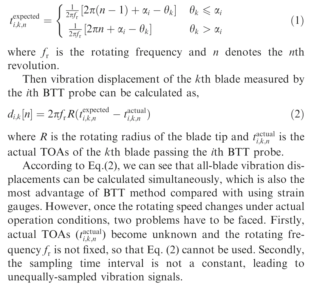
In time domain,the basis of BTT method is to measure the Times of Arrival (TOAs) when each blade passes each BTT probe. When there are no blade vibrations under ideal conditions,theoretical TOAs of each blade will only be a function of rotating speed,rotating radius and its circumferential position.Obviously,if these parameters are fixed,then theoretical TOAs are known in advance. While there are blade vibrations, the blades will pass BTT probes earlier or later than normal. In this case, actual TOAs will deviate from those obtained in the undisturbed conditions. These time differences will be as a function of vibration frequency and amplitude during operations.
Let the bladed-disk rotate clockwise at a constant speed.Under ideal conditions, the expected TOAs of the kth blade passing the ith BTT probe can be calculated as
2.2. BTT measurements in angular domain
As we all know that angular sampling has always been applied to deal with variable speeds.It can be seen from Fig. 1 that the angular positions of BTT probes are fixed.Thus BTT sampling is a natural angular sampling processing, which is independent of rotating speed. Then we will derive blade vibration displacements in angular domain, instead of time domain.
Theoretical angles of the kth blade passing the ith BTT probe under no vibrations can be represented as,

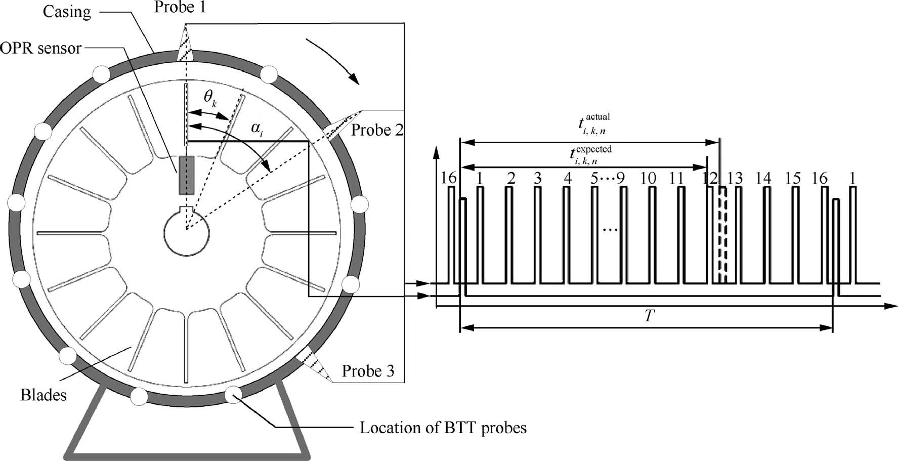
Fig. 1 Schematic diagram of BTT method.
Next,let the rotating speed of each revolution be fixed,then actual angles of the kth blade passing the ith BTT probe can be calculated as,

where Tis the period of the jth revolution; fis the rotating frequency of the nth revolution;ω=2πf;tis the measured passing time of the kth blade passing the ith BTT probe in the nth revolution.
Combining Eq. (3) and Eq. (4), angular-domain vibration displacement of the kth blade measured by the ith BTT probe can be calculated as,

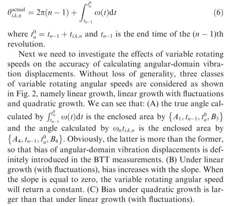
Based on Eqs. (3)–(5), we can see that angular-domain vibration displacement is strongly related to the rotating angular speed in the nth revolution. It should be that the rotating angular speed of each revolution is assumed to be constant in Eq. (4).If this assumption does not hold,bias will be introduced into the actual angles.Furthermore the variable rotating angular speed is denotes as ω(t ),then Eq.(4) will be rewritten as,
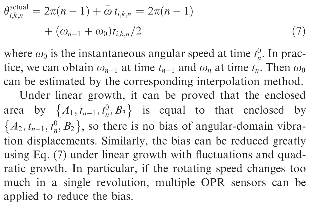
In order to deal with bias of angular-domain vibration displacements due to variable rotating speed, an improved version of Eq. (4) is proposed as follows.
2.3. MCAS scheme of BTT vibration signals under variable speeds
True angular-domain vibration displacement of the kth blade is denoted as y(θ), which will be sampled for I times during each revolution according to Fig.1.Based on Eq.(3),the ideal impulsive sampling function can be represented as,
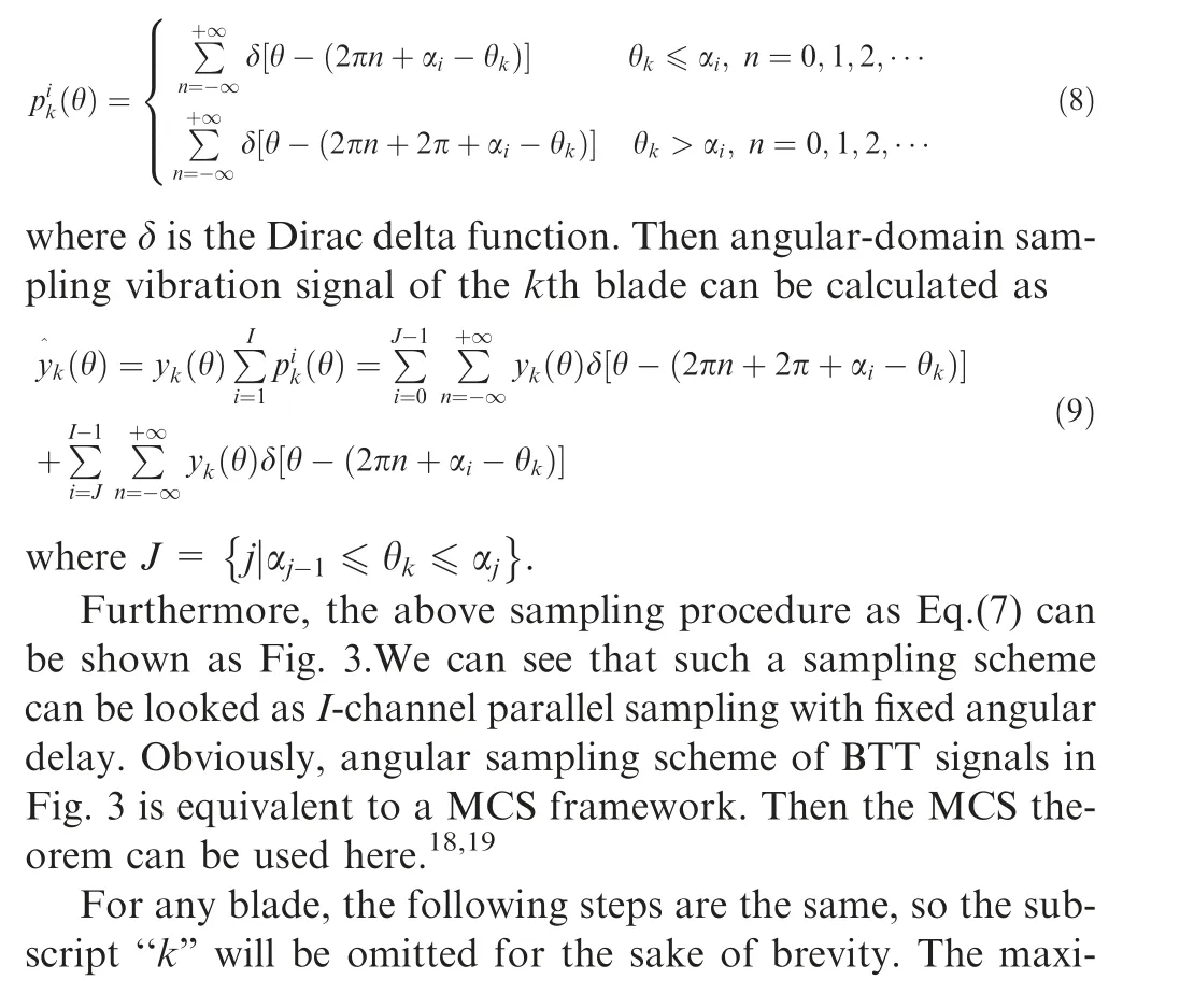

Fig. 2 Three classes of variable rotating angular speeds.
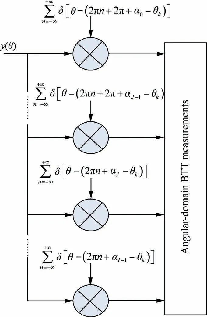
Fig. 3 Angular sampling scheme of BTT vibration signals.
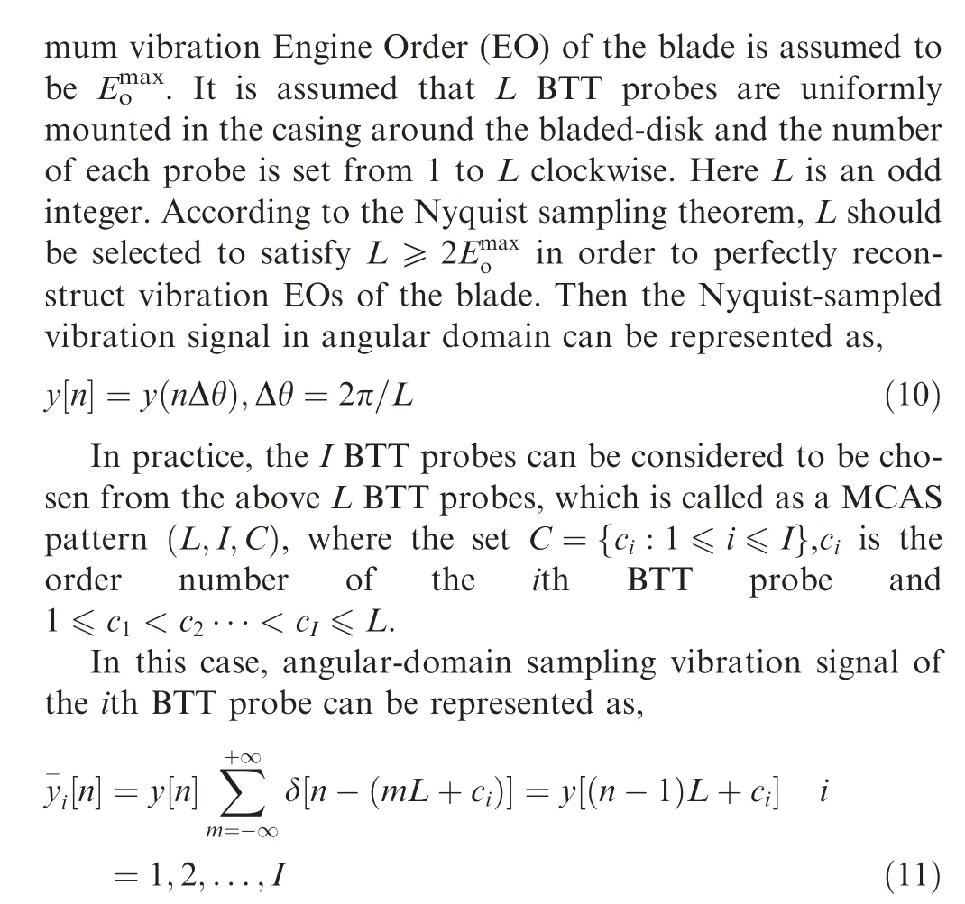
where the sampling angle interval of each BTT probe is denoted as Δθ= LΔθ. Furthermore, the MCAS scheme of BTT vibration signals can be plotted as Fig. 4.
3. Compressed sensing model of BTT vibration signals in order domain
3.1. Construction of compressed sensing model
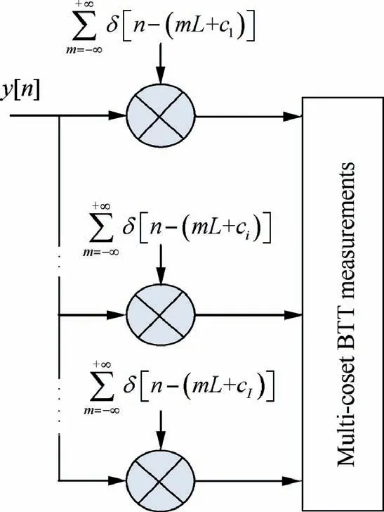
Fig. 4 MCAS scheme of BTT vibration signals.
In practice, I has to be selected so that I ≪L due to the restrictions of space and cost. It is not difficult to understand that the BTT vibration signals are also under-sampled in angular domain. That is to say, vibration EOs of the blade cannot be perfectly reconstructed by directly using y[n ].However, we can seek another idea. If we can reconstruct Nyquist-sampled y[n ] by using yi [n ], true vibration features of the blade will also be obtained. In order to achieve it,we will build the relation between y[n ] and yi [n ] in order domain as follows.
Firstly,we will define an intermediate angular sampling signal as follows.
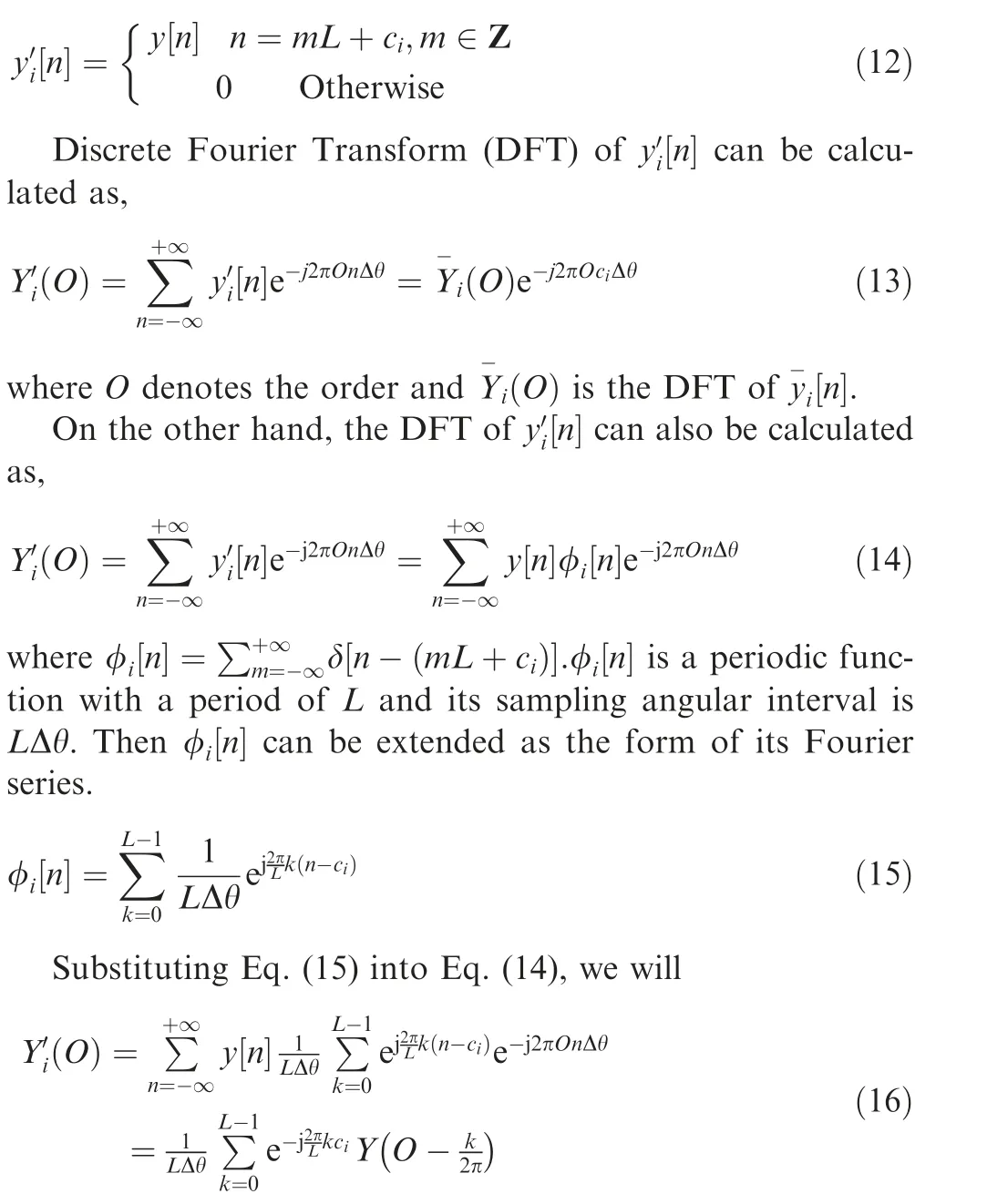
where O ∈[-L/2,L/2] and Y O( ) is the DFT of y[n ].
By combing Eq.(13) and Eq.(16), we will have
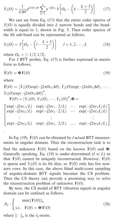
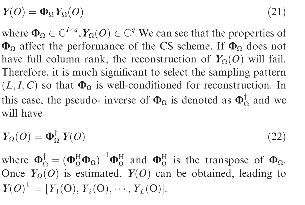
The index set of non-zero sub-bands of Y(O)is assumed as Ω with q elements. The matrix Y(O) is formed by selecting the rows of Y(O) with indices Ω and Φis formed by selecting the columns of Φ with the same indices Ω. Then Eq.(18) is reduced to
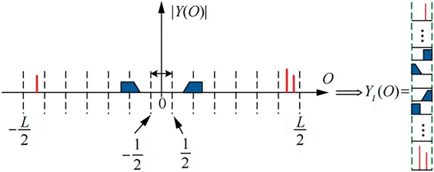
Fig. 5 Relation between Y(O) and Yl(O).
3.2. Optimization criterion of MCAS pattern
2As mentioned above, we should design the optimal sampling pattern (L,I,C) in order to uniquely reconstruct Y(O). Without loss of generality,L is assumed to be pre-selected and fixed.Then how to determine I,C will be investigated in this section.
As for blind multi-band blade vibrations,the index set Ω is unknown in advance, so that Eq. (22) is hardly used in practice. As we all know that the solution of the Pproblem is Nondeterministic Polynomially (NP) hard, so we often seek a near-optimal solution to approximate the exact solution of the Pproblem.The common way is to replace the Pproblem by the Pproblem as follows.

where ‖·‖is the ℓ-norm.
Generally speaking, The Pproblem can be solved by the optimization theory. Then the successive question is: under what conditions can we guarantee that the solution of the Pproblem is that of the Psolution as well? A most interesting result of this question has been presented by Cotter et al..Firstly,r=‖Y( O )‖is denoted as the number of nonzero elements in the vector Y(O), namely the sparsity. The matrix Spark of Φ is defined as σ=spark(Φ), where σ is the largest possible non-negative integer such that every sub-group of σ columns from Φ are linearly independent and at least one sub-group of σ+1 columns from Φ are linearly dependent.Then the condition that a unique solution of the Pproblem exists can be defined as the following theorem.
Theorem: Letting Rank(Y(O)) denote the rank of Y(O),Y(O) will be the unique solution of the problem P, if
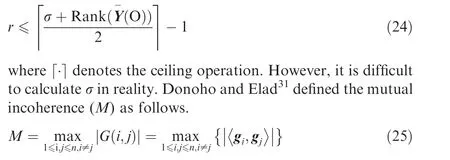
where G=ΦΦ,G(i,j)is the(i,j)th entry of the Gram matrix G;gand gare the ith and jth columns of G.Furthermore,the relation between M and σ is given as,
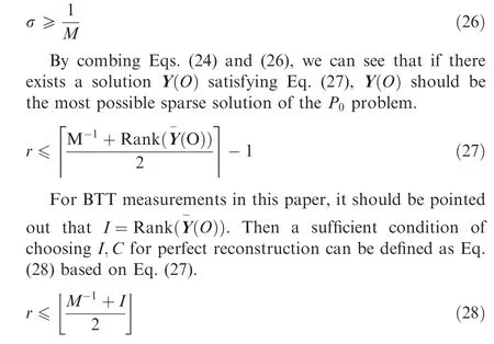

Obviously,The value of M strongly depends on the number and configuration of BTT probes. Thus we can see from Eq.(28) that choosing I,C is strongly related to the sparsity of blade vibration.
In engineering applications,the optimization criteria of I,C may include the following steps:
(1) The sparsity r can be firstly estimated based on prior knowledge or physical mechanism;
(2) I can be determined by allowable installation locations or pre-selected from the least possible number;
(3) Once r and I are chosen, Eq. (28) can be used to find a feasible C. Otherwise, we can increase I and so forth.
In particular, it must be emphasized that the above condition is just sufficient, not necessary.
After the sampling pattern (L,I,C) is determined, many existing methods can be applied to solve the Pproblem. In this paper, we consider the following algorithms that are used in CS applications: (A) Orthogonal Matching Pursuit (OMP),(B) Multiple Signal Classification (MUSIC), (C) Basis Pursuit Denoising(BPDN),and(D)Modified Focal Underdetermined System Solver (MFOCUSS).
4. Numerical results and discussion
4.1. Simulated multi-band vibration signals
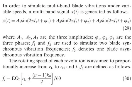

In this paper,simulation parameters are set as:r=1200 r/min, r=1250r/min, EO= 2, EO= 3, A= 1 mm, A=0.5 mm, A= 1mm, f=50 Hz and φ= φ= φ=0.
Furthermore, in order to evaluate the performance of different reconstruction algorithms, two metrics are referred to the definition.The first one is the Support Reconstruction Ratio (SRR) defined as follows.

where y[i] and ^y[i] are the original and reconstructed multiband signals, respectively. RRMS can be considered as the reconstruction error in angular domain. Obviously, the signal tends to be perfectly reconstructed when RRMS is close to zero or SRR is close to one.
In order to simulate the MCAS process, the Nyquist sampling rate is chosen as L=13 and the corresponding angular-domain sampled signals are shown in Fig. 6. Then for any given sampling pattern (L,I,C), the corresponding simulated MCAS samples can be generated based on Eq. (9).
4.2. Optimization of sampling pattern
As for different blind multi-band vibration signals, the expected number of BTT probes for perfect reconstruction can be estimated based on Eq. (26). In reality, the sparsity is unknown in advance, so we just investigate the relation between the sparsity of the signal and the MCAS pattern.The detailed results are listed in Table 1. For example, when the number of BTT probes is equal to nine, blind multi-band signals with a sparsity less than five can be definitely reconstructed. In addition, we can understand from Table 1 that the condition of Eq. (26) is just sufficient, not necessary. For example, when the number of BTT probes is equal to three,we can also use four BTT probes for perfect reconstruction if the optimal C is applied. Thus how to mount BTT probes is also much important and Table 1 can provide useful guidelines for engineering applications.
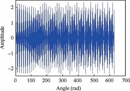
Fig. 6 Nyquist-sampled simulation signals in angular domain.
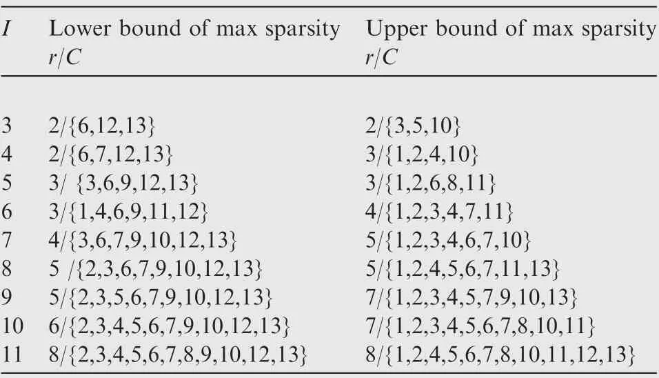
Table 1 Relation between sparsity and MCAS pattern.
For the simulation signal, we can see that its sparsity in order domain is equal to three. Then we choose two MCAS patterns as (13, 4, {6,7,12,13}) and (13, 4, {1,2,4,10}). Reconstruction results are shown in Fig. 7. It can be seen that sensors’positions have strong influences on the reconstruction performance. Under C={1,2,4,10}, the multi-band signal can be reconstructed very well in both angular domain and order domain. While under C={6,7,12,13}, the reconstruction is bad and false order appears.Also,we can see that the number of BTT probes can be reduced by optimizing C for given I.
4.3. Comparisons of different reconstruction algorithms
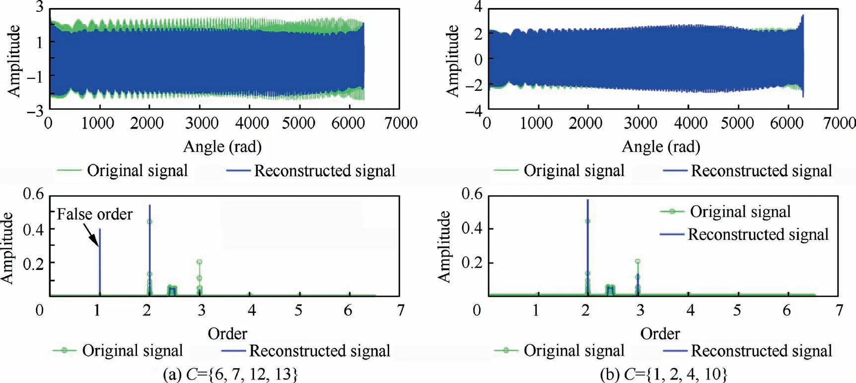
Fig. 7 Reconstruction results under two MCAS patterns.
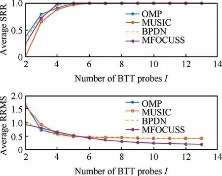
Fig. 8 Comparisons of four reconstruction algorithms.
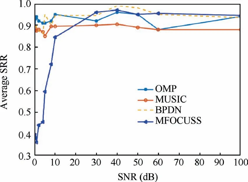
Fig. 9 Reconstruction results under different SNRs.
Firstly,the sparsity of the simulated multi-band signal is equal to 3.Then the number of BTT probes(I)is chosen from 2 to L.For each I,100 different MCAS patterns(C)are randomly generated and the corresponding angular-domain BTT signals are sampled to calculate the average SRR. Here, the four reconstruction algorithms(OMP,MUSIC,BPDN and MFOCUSS)are applied respectively. In the end, the average SRR is calculated under each algorithms and the results are shown as Fig. 8. We can see that: (A) Average SRR increases with I for each algorithm, which testifies that increasing I can obviously improve the reconstruction performance; (B) When I is larger than 4,perfect reconstructions can almost be definitely carried out.On the other hand,when I is less than 4,the reconstruction errors will be large.This conclusion is consistent with the results of Table 1 and Eq.(26);(C)The average performances of MFOCUSS and BPDN are better than other two algorithms.
4.4. Effects of measurement noises
In theoretical analysis, noises are not considered. In reality,measurement noises indeed exist, which will affect the reconstruction process. In order to investigate the influences, measurement noises with different Signal-to-Noise Ratios(SNRs) are added into the simulated multi-band signal. 100 different MCAS patterns (C) are randomly generated and the corresponding angular-domain BTT noised signals are sampled to calculate the average SRR. The results are shown in Fig.9.We can see that:(A)Noises decrease the reconstruction performances of all the four algorithms; (B) When the SNR is low, the averaged performance of MFOCUSS is bad.Conversely, when the SNR is high, the averaged performance of MFOCUSS is the best; (C) Noises have the least influences on BPDN among the four algorithms.
In summary, the overall performance of BPDN is the best among the four algorithms according to the reconstruction error and sensitivity to noises.In addition,the most important is that BPDN can run without any prior information of the original signal, including the sparsity and the number of non-zero order slices. Therefore, the BPDN algorithm may be selected for future experimental studies or practical applications.
4.5. Effects of slowly and fast variable rotating speeds
As mentioned in Section 2.2, the degree of variable rotating speeds will affect the accuracy of calculating angular-domain vibration displacements. In this case, compressed sensing performance of BTT vibration signals in order domain is definitely different under different rotating speeds. In order to testify it, here the maximum rotating speed (r) is set to four different values to simulate four accelerations of speed:r=1500, 2000,2500, 3000 r/min.Then reconstructed results are shown in Fig. 10. We can see that the reconstruction performance decreases with the accelerations of rotating speed.In particular, wrong result will appear under fast variable rotating speeds. Thus the proposed method is fit for slowly variable rotating speeds.
5. Conclusions
(1) A MCAS model of BTT vibration signals is developed in this paper and this sampling pattern can deal with the problem due to variable rotating speeds.
(2) A compressed sensing model of BTT vibration signals is derived in order domain.

Fig. 10 Reconstruction results under four variable rotating speeds (C={1,2,4,10}).
(3) For the MCAS pattern, a sufficient condition of the number of BTT sensors is derived for perfect reconstruction and optimal placement of BTT sensors is determined by minimizing the condition number.
(4) As for fast variable rotating speeds, multiple OPR sensors can be used and an improved method of calculated angular-domain vibration displacement needs to be studied in future work.
(5) The proposed method is testified by the simulation results. In the future, experimental validations should be done to show its feasibility.
Declaration of Competing Interest
The authors declare that they have no known competing financial interests or personal relationships that could have appeared to influence the work reported in this paper.
Acknowledgement
This study was supported by the National Natural Science Foundation of China (No. 51975206).
 CHINESE JOURNAL OF AERONAUTICS2021年9期
- CHINESE JOURNAL OF AERONAUTICS的其它文章
- Optimal trajectory and downlink power control for multi-type UAV aerial base stations
- Effects of flow parameters on thermal performance of an inner-liner anti-icing system with jets impingement heat transfer
- Effects of wing flexibility on aerodynamic performance of an aircraft model
- Aerodynamic performance enhancement of co-flow jet airfoil with simple high-lift device
- Adaptive fuzzy terminal sliding mode control for the free-floating space manipulator with free-swinging joint failure
- Influence of longitudinal-torsional ultrasonicassisted vibration on micro-hole drilling Ti-6Al-4V
