Design and Analysis of Spatial Modulation Based Orthogonal Time Frequency Space System
Yingchao Yang,Zhiquan Bai,*,Ke Pang,Piming Ma,Haixia Zhang,Xinghai Yang,Dongfeng Yuan
1 Shandong Provincial Key Lab.of Wireless Communication Technologies,School of Information Science and Engineering,Shandong University,Qingdao 266237,China
2 Shandong Provincial Key Lab.of Wireless Communication Technologies,School of Control Science and Engineering,Shandong University,Jinan 250061,China
3 College of Information Science and Technology,Qingdao University of Science and Technology,Qingdao 266061,China
Abstract:In this paper,we design a spatial modulation based orthogonal time frequency space(SMOTFS)system to achieve improved transmission reliability and meet the high transmission rate and highspeed demands of future mobile communications,which fully utilizes the characteristics of spatial modulation(SM)and orthogonal time frequency space(OTFS)transmission.The detailed system design and signal processing of the SM-OTFS system have been presented.The closed-form expressions of the average symbol error rate(ASER)and average bit error rate(ABER)of the SM-OTFS system have been derived over the delay-Doppler channel with the help of the union bounding technique and moment-generating function(MGF).Meanwhile,the system complexity has been evaluated.Numerical results verify the correctness of the theoretical ASER and ABER analysis of the SM-OTFS system in the high signal-to-noise ratio(SNR)regions and also show that the SM-OTFS system outperforms the traditional SM based orthogonal frequency division multiplexing(SM-OFDM)system with limited complexity increase under mobile conditions,especially in high mobility scenarios.
Keywords:orthogonal time frequency space(OTFS);spatial modulation based OTFS(SM-OTFS); delay-Doppler domain; average symbol error rate(ASER);average bit error rate(ABER)
I.INTRODUCTION
The fifth-generation(5G)mobile communication system is looking forward to achieving much better spectral efficiency,higher capacity,and lower end-to-end latency[1]in comparison with the fourth-generation(4G)system.As a core technology in 4G system,orthogonal frequency division multiplexing(OFDM)[2]is capable of achieving high spectral efficiency and excellent communication performance in timevariant frequency selective channels.It has great potential in future wireless communications.However,OFDM still suffers performance loss due to the serious inter-carrier interference of the fast time-variant channels under high Doppler spread communication scenarios,such as vehicle-to-vehicle(V2V)[3]and highspeed railway(HSR)[4]communications,which are the main application scenarios in 5G and future mobile communications.
To deal with the influence of the fast time-varying wireless mobile channels,orthogonal time frequency space(OTFS)modulation has been proposed recently[5].R.Hadaniet al.presented a general framework of OTFS modulation and proved that the OTFS system could be implemented by adding inverse symplectic finite Fourier transform(ISFFT)and symplectic finite Fourier transform(SFFT)into the traditional OFDM system[5,6].OTFS modulation operates in the delay-Doppler domain and achieves significant advantages in system performance compared with OFDM working in the time-frequency domain.The delay-Doppler domain can offer another new form of signal representation.According to the delay-Doppler representation,each modulated signal in one OTFS transmit frame can be spread on two dimensional(2D)delay-Doppler orthogonal basis function,which crosses the whole time-frequency domain.Meanwhile,OTFS modulation can convert the time-variant time-frequency channel into the time-invariant delay-Doppler channel,while it achieves full diversities of both time and frequency to enhance the communication performance,especially in the mobile 5G scenarios,e.g.,enhanced mobile broadband(eMBB),ultrareliable low latency communication(URLLC),internet of things(IoT),millimeter-wave communication,and communications under high mobility conditions,such as V2V and HSR.
Current studies about OTFS mainly focus on OTFS design and analysis[7–9],signal detection[10,11],and channel estimation[12–14].P.Ravitejaet al.derived a simple and sparse input-output matrix form of the traditional OTFS scheme in the delay-Doppler domain[7].The discrete-time expression of the OTFS system based on OFDM was proposed in[8,9],leading to a deep insight into the OTFS design as well as its simpler structures of the modulator and demodulator.A joint interference cancelation and signal detection algorithm of the OTFS system was proposed in[10]with low complexity but better efficiency.Furthermore,T.Zemenet al.proposed a lowcomplexity equalizer combining soft-symbol feedback with the minimum mean square error(MMSE)equalization to eliminate the inter-symbol interference(ISI)and enhance the average bit error rate(ABER)performance of the OTFS system[11].Besides,an orthogonal matching pursuit(OMP)algorithm with three dimensional(3D)channel estimation in OTFS was proposed in[12],which obtains accurate OTFS channel estimation with low pilot overhead.For the uplink channel estimation of the path division multiple access based massive multiple-input multiple-output(MIMO)OTFS(MIMO-OTFS)networks,M.Liet al.adopted the 3D OMP algorithm to extract the channel parameters,which achieves good estimation performance[13].Furthermore,considering the validity and robustness of channel estimation,an expectation maximization based variational Bayesian framework and a path scheduling algorithm were proposed in[14]to complete the uplink and downlink channel estimation in massive MIMO-OTFS system,respectively.
Spatial modulation(SM)is considered as a particular case of MIMO technology[15,16],which inherits the advantages of MIMO and avoids the corresponding deficiencies,such as inter-antenna synchronization(IAS),inter-channel interference(ICI),and the need of multiple radio frequency chains.Meanwhile,SM can exploit the transmit antennas’ spatial positions to carry extra bits and further enhance the system spectral efficiency.More importantly,SM has good flexibility and high adaptability and can be jointly designed with various transmission technologies.SM based OFDM(SM-OFDM)can resist frequency-selective fading,eliminate complex equalization,solve the problems of IAS as well as ICI,and further enhance the system spectral efficiency[17–25].R.Meslehet al.presented a fundamental structure of the SM-OFDM scheme in[17].Additionally,the ABER performance of the SM-OFDM system was analyzed in[18,19].A symbol-by-symbol detector for SM-OFDM systems was designed in[20]for eliminating the impact of carrier frequency offsets and considerably improving the system performance.S.Nusenuet al.studied an SM-OFDM scheme with frequency diverse array antennas in[21]to achieve better system ABER and capacity than the phased-array SM-OFDM system.An iterative soft compensation method was investigated in[22]to get rid of the influence of the clipping noise in SM-OFDM systems.Furthermore,the ABER performance of the SM-OFDM system with precoding was derived and analyzed in[23].Lowcomplexity detectors for the SM-OFDM system were studied based on the compressive sensing and sequential Monte Carlo theory in[24,25]to improve the detection accuracy.Moreover,L.Xiaoet al.proposed a novel OFDM scheme adopting the rectangular differential technique and index modulation in[26],which is an extension of SM and can provide considerable performance gain by exploiting the benefits of available channel state information(CSI).
Inspired by the characteristics of the SM-OFDM system,we propose the SM based OTFS(SM-OTFS)system to improve the spectral efficiency and significantly enhance the system reliability in mobile communications,which has not been studied to the best of our knowledge.SM-OTFS system makes a better trade-off between the system complexity and the transmission performance.The main contributions of our work are summarized as follows.
1)SM-OTFS scheme is proposed to further enhance the system spectral efficiency and transmission reliability,which makes full use of the characteristics of both SM and OTFS.The system model of the SMOTFS scheme is provided,and its signal processing is elaborated correspondingly.
2)With the help of the union bounding technique as well as moment-generating function(MGF),the theoretical closed-form expressions of the average symbol error rate(ASER)and ABER of the proposed SMOTFS system with maximum likelihood(ML)detection are derived respectively over the time-invariant delay-Doppler channel transformed from the fast timevariant time-frequency channel.Meanwhile,the system complexity of the SM-OTFS system has also been analyzed.
3)Numerical results show the correctness of our theoretical derivations of the ASER and ABER performance of the proposed SM-OTFS system.Moreover,the SM-OTFS system achieves a significant performance improvement with a slightly increased complexity compared with the traditional SM-OFDM system under different system configurations,especially in high mobility scenarios.
The remainder of this paper is organized in the following.We first introduce the OTFS modulation and propose the SM-OTFS system in Section II.Then,a detailed signal processing of the SM-OTFS system is described.In Section III,we derive the theoretical closed-form expressions of the ASER and ABER of the SM-OTFS system under the delay-Doppler channel with the union bounding technique and MGF,and the complexity of the SM-OTFS system is also investigated.Numerical results and analysis of the proposed SM-OTFS system have been provided in comparison with the conventional SM-OFDM system in different mobile scenarios in Section IV.At last,the conclusions are drawn in Section V.
Notations:The scalars,vectors,and matrices are represented by lowercase or uppercase,boldface lowercase,and boldface uppercase,respectively.The operations of(·)T,(·)∗,and(·)Hdenote transposition,conjugation,and Hermitian transposition.Moreover,⊗is the Kronecker product operation,|·|is the modulus operator,‖·‖Fmeans the Frobenius-norm operator,E[·]indicates the expectation operator.
II.SYSTEM MODEL
2.1 OTFS System Model
Figure 1 depicts the model of the OTFS system that modulates the information in the delay-Doppler domain.The impulse response of the time-variant channel in the system is expressed with the sparse delay-Doppler representation.OTFS can be realized by deploying ISFFT and SFFT on the consecutiveNOFDM symbols transmitted onMsub-carriers.As shown in Figure 1,we assume thatxDD(z,l)(z=0,...,N−1 andl=0,...,M−1)represents the modulated delay-Doppler domain signal at thelth delay and thezth Doppler within an OTFS transmit frame.At the transmitter,the transmit signal is transformed from the delay-Doppler domain into the time-frequency domain based on the ISFFT first,and the time-frequency signal is written as

Figure 1.OTFS system model.

Figure 2.System model of the SM-OTFS scheme.

withn=0,...,N −1 andm=0,...,M −1.
Then,the time-domain signals(t)transformed from the signalXTF[n,m]in the time-frequency domain can be obtained according to the Heisenberg transform[5],which can be denoted as

wheregtx(·)is the transmit pulse,Tdenotes the OFDM symbol duration,and Δfis the frequency interval between two neighboring sub-carriers of OFDM.
The time-domain signals(t)is conveyed to the receiver via a time-variant channel.Considering the additive white Gaussian noise(AWGN)n(t)at the receiver,the received time-domain signal is obtained as

whereh(τ,v)denotes the impulse response of the time-variant channel,τrepresents the channel delay,andvis the Doppler shift.
The receiver performs the inverse operations of the transmitter and converts the received time-domain signalr(t)into the delay-Doppler domain signalyDD(z,l).First,the time-frequency domain signalY TF[n,m]can be acquired fromr(t)by the Wigner transform,the inverse operation of the Heisenberg transform,and it can be written by

whereAgrx,r(τ,v)denotes the cross ambiguity function,and it can be represented by

wheregrx(·)is the received pulse.
Then,the received delay-Doppler domain signalyDD(z,l)can be obtained from the signalY TF[n,m]in the time-frequency domain according to the SFFT,and it is expressed as

2.2 SM-OTFS System Model
With the purpose of improving the system spectral efficiency,eliminating the ICI,and enhancing the transmission reliability in high mobility scenarios,we design the SM-OTFS system by utilizing the principle and characteristics of SM and OTFS.As shown in Figure 2,the SM-OTFS system hasNttransmit antennas andNrreceive antennas,whereNt=2a,ais a positive integer,andNrcan be any positive integer.Since one SM-OTFS transmit frame consists ofNconsecutive independent SM-OFDM symbols conveyed onMsub-carriers,Kbits can be sent in one SM-OTFS frame withK=M×N×log2(NtMs),whereMsis the modulation order.
The signal processing of the proposed SM-OTFS system is described in the following.At first,the random delay-Doppler domain information bit sequence b=[b1b2··· bK]enters the transmitter and is assigned into a log2(NtMs)× NMbinary matrix Q transmitted in one SM-OTFS transmit frame via serialto-parallel(S/P)converter.Then,Q is further mapped to another delay-Doppler domain transmit signal matrix X with dimensionNt×NMas
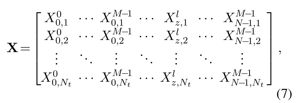
wherelocating at thepth row and(zN+l+1)th column of X withz∈{0,1,...,N −1},l∈{0,1,...,M −1},andp∈{1,2,...,Nt},represents the modulated signal at thelth delay and thezth Doppler sent from thepth transmit antenna in one SM-OTFS transmit frame.According to the principle of SM,each column of Q determines a quadrature amplitude modulation(QAM)or phase shift keying(PSK)modulated signal and a corresponding transmit antenna index,which is shown in each column of X with only one non-zero element.Additionally,each row vector of X represents the transmit delay-Doppler domain signals conveyed by different transmit antennas.After SM,the transmitter converts the delay-Doppler domain signals in each row vector of X into the time-frequency domain signals by the ISFFT at each transmit antenna.Then,the OFDM modulator corresponding to different transmit antennas will transform the input time-frequency domain signals into the time-domain signalsSi(t)by the Heisenberg transform shown as

The transmit signal matrix with time domain components for all the transmit antennas can be represented as S(t)and written as

Each row of S(t)is then sent to the receiver simultaneously fromNtdifferent antennas via the timevariant MIMO channel H(t).We presume that the time-variant multipath Rayleigh fading channel is employed,where the channel delays and Doppler shifts corresponding to each path are different.Thus,H(t)is a block matrix withNr×Ntvectors,and the length of each vector isP,wherePis the number of multipaths.H(t)can be expressed as


withwhereαqpi,τi,andviare defined as the channel coefficient,delay,and Doppler shift of theith path,respectively.In addition,the channel coefficientαqpiis a complex Gaussian random variable with zero mean and unit variance denoted asCN(0,1).

The received time-domain signal matrix Y(t)in the receiver is written as After OFDM demodulation with Wigner transform and SFFT operation,the received delay-Doppler domain signal at thelth delay and thezth Doppler for theqth receive antenna can be expressed as


with

and

Accordingly,the overall received delay-Doppler domain signal vector in the receiver for thelth delay and thezth Doppler is written as

where HDD(z,l)is the corresponding delay-Doppler channel response matrix,xDD(z,l)is the((z −1)N+l)th column of the transmit signal matrix X,and the AWGN vector can be further represented by nDD(z,l)=.
Subsequently,the received delay-Doppler domain signals can be detected and recovered based on the maximum ratio combining(MRC)or ML detection.With MRC algorithm,the estimated index of the active transmit antennaand the detected modulated signalcan be calculated respectively as
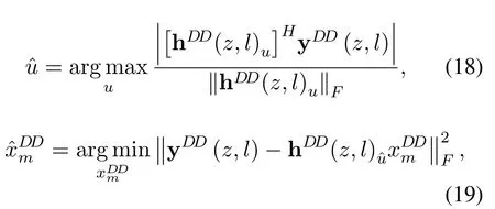
where hDD(z,l)urepresents theuth column of HDD(z,l)withu∈{1,...,Nt}andm∈{1,...,Ms}.
It can be recognized from(18)and(19)that the MRC detection is performed sequentially to detect the activated transmit antenna index and the modulated signal,which has much lower complexity than the universal search of the ML algorithm.However,its detection error probability depends on whether the activated transmit antenna is recovered correctly or not in the first step.If the estimation of the activated transmit antenna is incorrect,the demodulation goes wrong.Therefore,MRC detection cannot achieve optimal performance.
Since the ML algorithm jointly detects all the possible combinations of the activated transmit antenna and the modulated signal,it can realize the best detection performance.With ML detection,the recovered signalDD(z,l)at thelth delay and thezth Doppler is obtained as

Eventually,after the MRC or ML detection in the receiver,the output delay-Doppler information bits can be retrieved according to the SM mapping rule via SM demodulator and parallel-to-serial(P/S)converter.Since SM utilizes the spatial information of the transmit antenna to carry additional information bits,the spectral efficiency of the proposed SM-OTFS system is enhanced by a factor of log2Nt/log2Msfor one transmit frame compared with the traditional OTFS scheme.Meanwhile,although the signals in the time domain are transmitted from the transmitter to the receiver simultaneously,only one transmit antenna is activated for each transmission instant and each subcarrier,which eliminates the ICI and solves the IAS in the MIMO-OTFS system as well.
2.3 Example of SM-OTFS Scheme
In this subsection,we take an example to illustrate the process of the SM-OTFS scheme.The parameters of the SM-OTFS system are set in the following.We adopt the 4QAM withMs=4.The numbers of the transmit antennas,the receive antennas,the sub-carriers,and the SM-OFDM symbols are set asNt=2,Nr=1,M=2,andN=2,respectively.Hence,a 12-bit sequence can be transmitted in the delay-Doppler domain during one SM-OTFS transmit frame.
Without loss of generality,we set the input bit sequence as b=[1 0 1 1 1 0 0 1 0 1 0 1].According to the fact that one SM-OTFS transmit frame containsNSM-OFDM symbols and each SM-OFDM symbol consists ofMmodulated signals,the input bit sequence b can be mapped into a binary matrix Q with dimension log2(NtMs)×NM.Q can be expressed as

Each column of Q determines both the modulated signal and the index of the activated transmit antenna.
Subsequently,according to the mapping rule shown in Table 1,Q is transformed to matrix X after SM,and X is written as
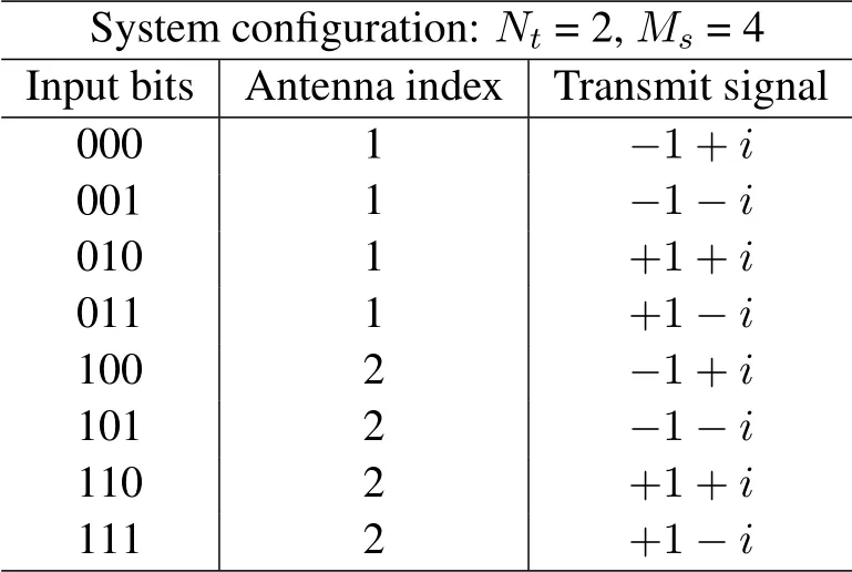
Table 1.Mapping rule of SM-OTFS.

Each row in X includes all the modulated delay-Doppler domain signals transmitted via the corresponding antenna.
Then,the ISFFT and OFDM modulator are employed to each row of X to transform the signal from the delay-Doppler domain to the time-frequency domain as well as from the time-frequency domain to the time domain.The resulting time-domain signal vectors are sent simultaneously to the receiver.
To illustrate the operation of the SM-OTFS system intuitively,we suppose that the receiver can acquire all the CSI by perfect channel estimation,while there exists no noise interference during the signal transmission.The received time-domain signal vectors at each receive antenna are demodulated with the corresponding OFDM demodulator and SFFT to obtain the delay-Doppler domain signals.After the MRC or ML detection,the output signal matrix Y can be recovered as the same as X because of the noise-free condition.
Furthermore,the estimations about the activated transmit antenna and the modulated signal in one SM-OTFS transmit frame can be obtained as(2 2 1 2)and(−1−i+ 1 +i+1+i −1−i),respectively.Finally,based on TABLE 1,the receiver can retrieve the input bit sequence from the estimated transmit antenna index and the demodulated signal successfully.
III.PERFORMANCE ANALYSIS OF SMOTFS SYSTEM
In this section,we focus on the theoretical performance analysis of the proposed SM-OTFS system based on the ML detection algorithm with perfect channel estimation.The closed-form expressions of both ASER and ABER of the SM-OTFS system are derived with the help of the union bounding technique[27]and MGF[28].Moreover,we also evaluate the complexity of the SM-OTFS system and the SM-OFDM system for comprehensive analysis.
3.1 ASER Performance
In this subsection,we provide the derivation of the theoretical closed-form ASER expression of the SMOTFS system.As illustrated in Section 2.2,Nconsecutive SM-OFDM symbols are transmitted onMsub-carriers in one SM-OTFS transmit frame.Here,we only consider one delay-Doppler domain transmit signal xDD(z,l)for thelth delay and thezth Doppler in an SM-OTFS transmit frame first.With the union bounding technique,we can calculate the corresponding ASER performance as[29]

It is observed from(23)that the key factor for the derivation of the ASER is to obtain the expression of.Based on the ML detection algorithm,the PEP is obtained as(24)where Pr[·]means the probability.

According to the PEP evaluation method in[30],the PEP in(24)conditioned on HDD(z,l)can be derived as(25).

Furthermore,substituting(17)into(25),we can compute the conditional PEP as
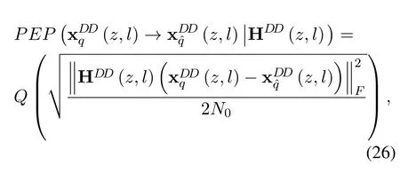
whereQ(·)indicates theQ-function withQ(x)=dt.
After mathematical manipulations based on theQfunction,the PEP can be further expressed as
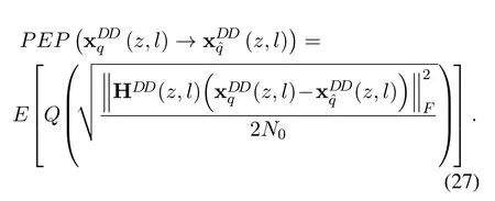
According to(27),we can further utilize the new form of theQ-functionin[31]and get the PEP as
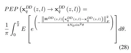
With the employment of the MGF,(28)can be further derived as

whereΨ(·)istheMGFofHence,according to[32],the PEP can be written as(30)withand.
Therefore,we can replace(23)with(30)and derive the ASER expression of the proposed SM-OTFS system for only one transmit signal in an SM-OTFS transmit frame,shown in(31).

Considering all the transmit signals in one SM-OTFS transmit frame,the closed-form ABER expression for the proposed SM-OTFS system can be finally obtained as(32).

3.2 ABER Performance
In the following,we further derive the theoretical closed-form ABER expression of the proposed SMOTFS system.With perfect channel estimation and the help of the union bounding technique,the closed-form ABER expression can be obtained similarly to ASER in Section 3.1.
Considering all theMNtransmit signals in one SMOTFS transmit frame,the theoretical ABER expression can be represented as[33]

In Section 3.1,we have obtained the PEP in(30).By substituting(30)into(33),we can eventually derive the theoretical ABER expression of the proposed SM-OTFS system as(34).

3.3 Complexity Analysis
The complexity of the SM-OTFS system,including the time complexity and the computational complexity,are investigated in this subsection.For an SMOTFS transmit frame,we first analyze the time complexity and then present the computational complexity of the receiver with ML and MRC detection algorithms,respectively.Furthermore,we also compare the complexity of the proposed SM-OTFS system with that of the traditional SM-OFDM system.Note that we set one SM-OFDM transmit frame withNconsecutive SM-OFDM symbols for fair comparison.
3.3.1 Time Complexity Analysis
We evaluate the time complexity of the SM-OTFS system based on ISFFT,inverse fast Fourier transform(IFFT),fast Fourier transform(FFT),and SFFT.In one SM-OTFS transmit frame,the time complexity of ISFFT can be expressed asMNlog2(MN)sinceMNtransmit signals in an SM-OTFS frame can be viewed as a sequence containingMNdiscrete points.For IFFT,FFT,or SFFT,its time complexity is the same as that of ISFFT.Thus,the time complexity of the SM-OTFS system in one SM-OTFS transmit frame can be calculated asCSM−OTFS−time=4MNlog2(MN).
The traditional SM-OFDM system has no ISFFT and SFFT compared with the SM-OTFS system.Hence,in one SM-OFDM transmit frame,the time complexity of the SM-OFDM system can be obtained asCSM−OFDM−time=2MNlog2M.
3.3.2 Computational Complexity Analysis
We mainly employ the number of summations and multiplications of the complex values in the receive detection process to measure the system computational complexity as in[34].For one transmit signal in an SM-OTFS transmit frame with ML detection,by analyzing(20),we can get the computational complexity asMsNt(2NtNr −Nt −Nr)[18].However,if MRC detection is employed in the receiver,the computational complexity becomes 2NtNr −Nt[35].For either one SM-OTFS transmit frame or one SM-OFDM transmit frame,it hasNMtransmit signals.Thus,the computational complexity of the SMOTFS system is equal to that of the SM-OFDM system in one transmit frame.With ML detection,the computational complexity for both the SM-OTFS system and the SM-OFDM system can be expressed asCML=MNMsNt(2NtNr −Nt −Nr).While for both the SM-OTFS system and the SM-OFDM system with MRC detection,they have the same computational complexity asCMRC=MN(2NtNr −Nt).
We notice that the time complexity of the SM-OTFS system is just a little higher than that of the SM-OFDM system,aboutand their computational complexities are the same.Since the SM-OTFS system can get much better performance for its inherent characteristics against the SM-OFDM system,the limited increase of the time complexity is actually acceptable.However,with the increase of the transmit antennas,the receive antennas,the sub-carriers,and the SM-OFDM symbols,the SM-OTFS system based on the ML detection,which outperforms the MRC detection,will get a very high complexity.Therefore,the performance and the complexity of the proposed SMOTFS system make a critical pair of trade-off factors for the optimal system design.The feasible optimal design of the SM-OTFS system and its corresponding detection algorithm can be further investigated to balance the system performance and complexity well.
IV.NUMERICAL RESULTS
This section provides the numerical results about the ASER,ABER,and the complexity of the proposed SM-OTFS system based on the ML detection with different system setups.In the simulation,the perfect CSI is available in the receiver,and the time-variantchannel shown in(10)is employed.The number of the multipaths is set to be 4,and each multipath corresponds to a unique delay and Doppler shift[36].Besides,the receiver is moving at a certain speed(kilometers per hour,Kmph).Without loss of generality,Table 2 shows the main system setups as well as the corresponding delay-Doppler parameters.
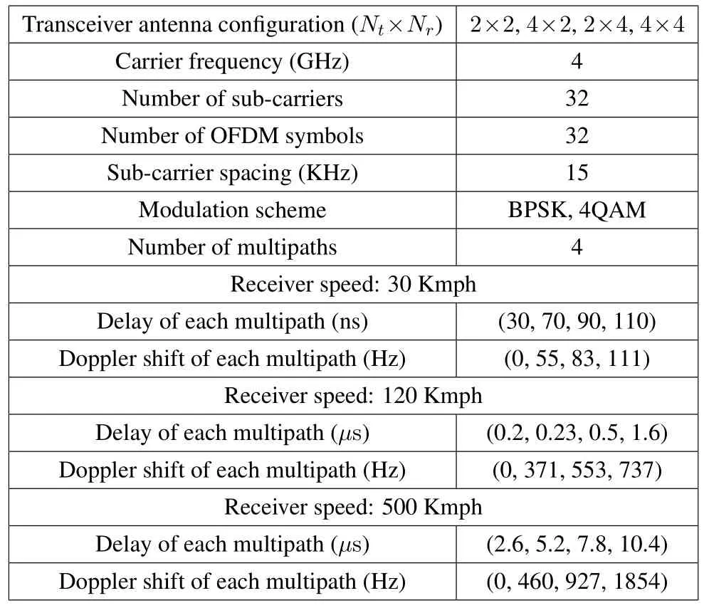
Table 2.System Parameters.
We provide the ABER performance of the proposed SM-OTFS system with different ML and MRC detection algorithms in Figure 3.We notice that the SMOTFS system based on the ML detection outperforms the SM-OTFS system based on the MRC detection for the spectral efficiency of 3 and 4 bits/symbol/subcarrier because the ML detection can complete traverse search and obtain higher diversity gains compared with the MRC detection[37].While we can observe from Figure 3 that the increase of the transmit antennas can result in higher ABER.When the ABER achieves 10−3,the SM-OTFS system with ML detection forNt=2 andNr=2 obtains about 1.8 dB gains compared with that forNt=4 andNr=2.This phenomenon happens because part of the information bits is carried by the transmit antennas in the SM-OTFS system.The growth of the transmit antenna number may improve the probability of error detection.Moreover,Figure 3 also illustrated that with the increase ofNr,the ABER performance can be enhanced.As shown in Figure 3,when the ABER achieves 10−2,the SM-OTFS system adopting ML detection withNt=2,Nr=4,and 4QAM can get about 6.3 dB gains compared with that withNt=2,Nr=2,and 4QAM.While adopting MRC detection,the SM-OTFS system withNr=4 outperforms that withNr=2 about 11.6 dB gains.Additionally,for the SM-OTFS system withNt=4 using either ML detection or MRC detection,the system’s ABER performance withNr=4 also outperforms that withNr=2.The ABER of the SM-OTFS system decreases with the increase ofNrbecause of the increased receive diversity.
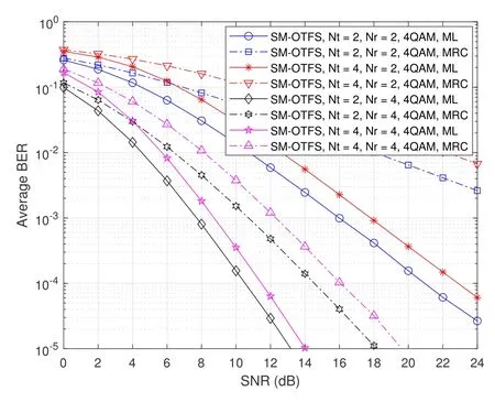
Figure 3.ABER performance of the SM-OTFS system based on ML and MRC detections with Nt =2 or Nt =4,Nr =2 or Nr =4,and 4QAM.
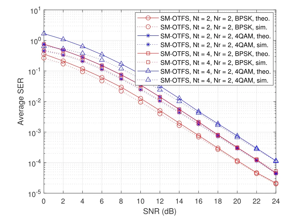
Figure 4.ASER performance of the SM-OTFS system with different Nt ,Nr and modulation schemes.
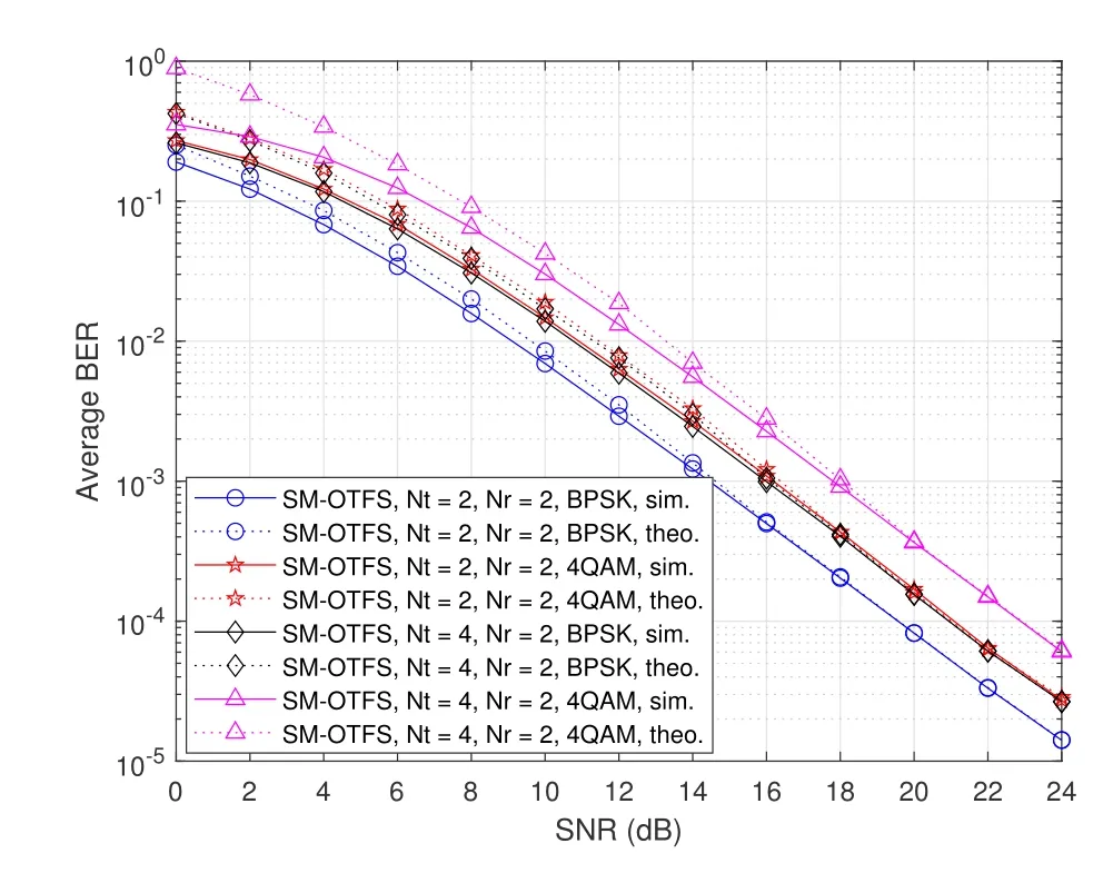
Figure 5.Theoretical and simulated ABER performance of the SM-OTFS system with different Nt and Nr (BPSK and 4QAM).
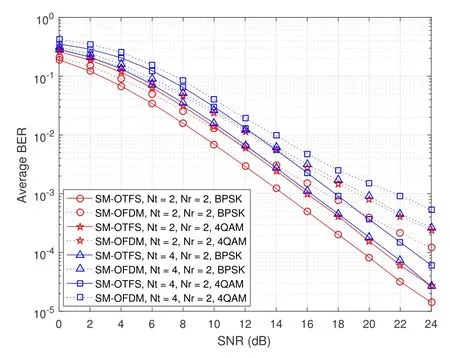
Figure 6.ABER performance of the SM-OTFS and SMOFDM schemes with Nt =2 or Nt =4,Nr =2 at the speed of 30 Kmph(BPSK and 4QAM).
Figure 4 demonstrates the simulated and theoretical ASER performance of the SM-OTFS system with differentNtand modulation schemes at the speed of 30 Kmph.It is found that there exists a small gap between the simulation and theoretical results in the low SNR regions,no matter what the number of transmit antennas and the modulation scheme are,because of the utilization of the union bounding technique as explained in[38].Moreover,with the increase of SNR,the theoretical ASER results match well with the simulation results,which proves the correctness of our theoretical derivation.Furthermore,at the spectral efficiency of 3 bits/symbol/sub-carrier,we observe that the SMOTFS system withNt=2,Nr=2,and 4QAM achieves almost the same ASER performance as that withNt=4,Nr=2,and BPSK.
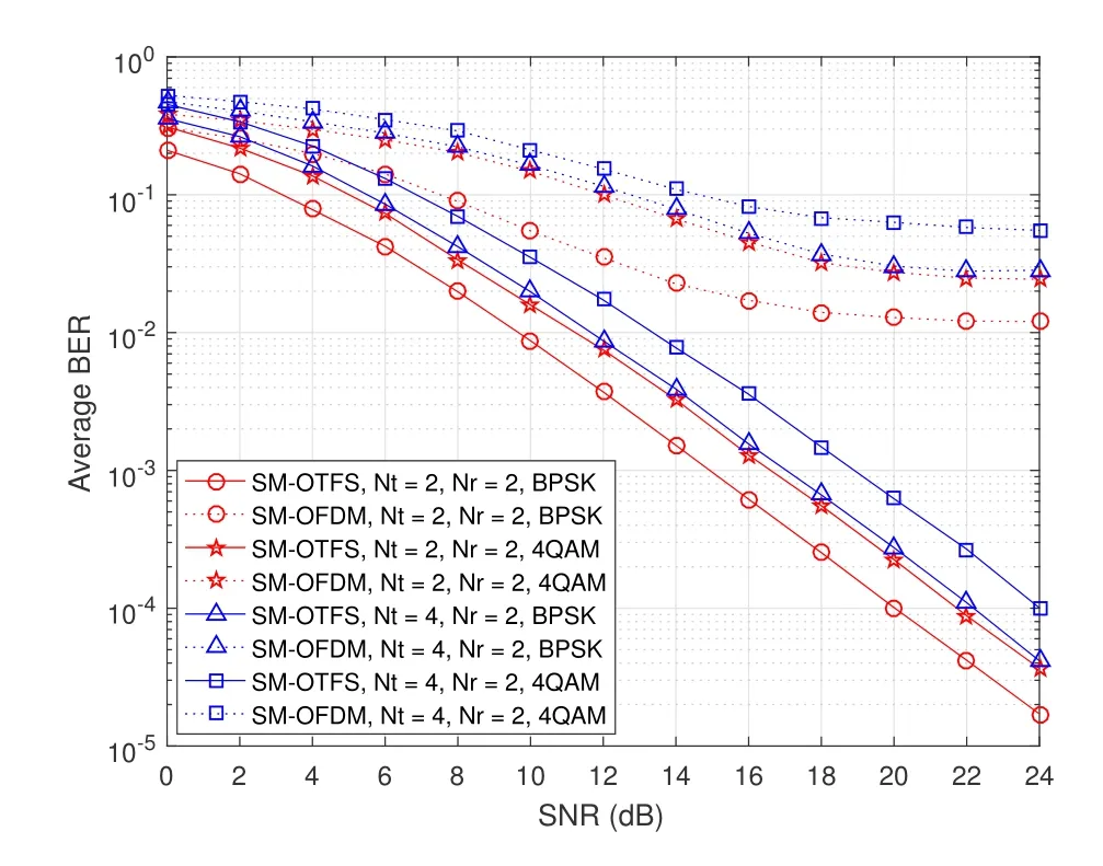
Figure 7.ABER performance of the SM-OTFS and SMOFDM schemes with Nt =2 or Nt =4,Nr =2 at the speed of 500 Kmph(BPSK and 4QAM).
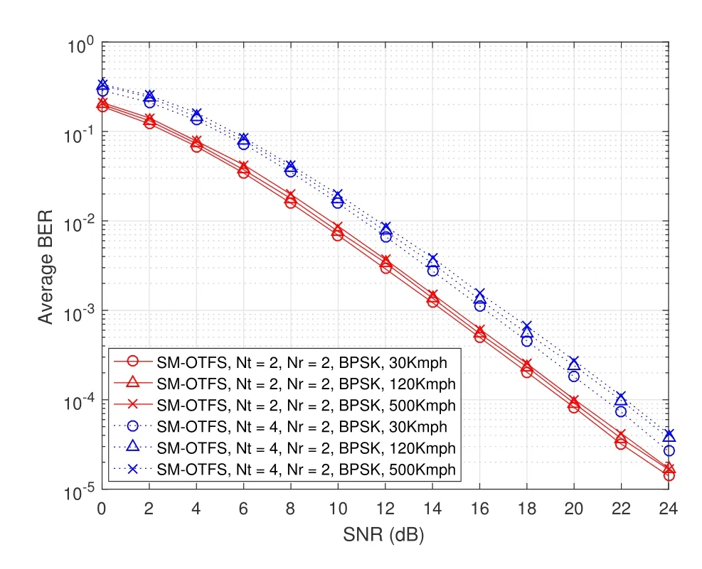
Figure 8.ABER performance of the SM-OTFS scheme with Nt =2 or Nt =4,Nr =2,and BPSK at different receiver speeds.
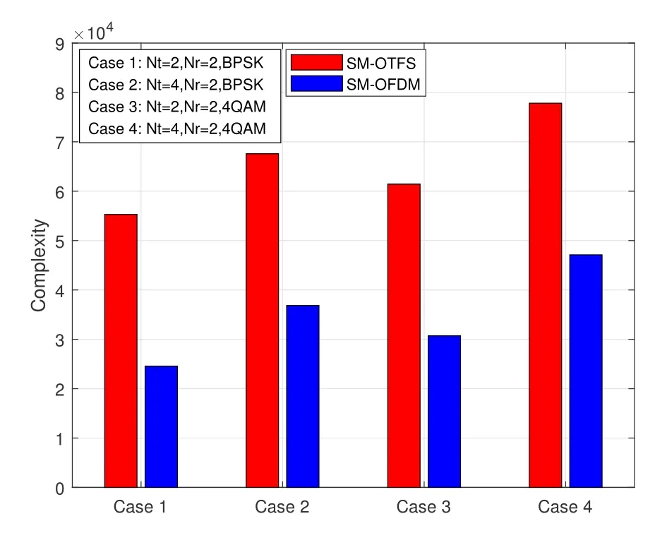
Figure 9.Complexities of SM-OTFS and SM-OFDM systems with M=32,N=32,and different antenna configurations.
We also exhibit the numerical results about the ABER performance of the SM-OTFS system at the receiver speed of 30 Kmph in Figure 5.A similar phenomenon happens like Figure 4.It is shown from Figure 5 that the ABER performance has a similar trend with the ASER performance for differentNtandNr.Also,the simulation results coincide well with the corresponding theoretical results in the high SNR regions.
The ABER performance of the proposed SM-OTFS system and the traditional SM-OFDM system at the receiver speed of 30 Kmph is given in Figure 6 with different system configurations.At the speed of 30 Kmph,a small Doppler spread of 111 Hz occurs,which may not cause severe inter-carrier interference.Figure 6 illustrates that the SM-OTFS system achieves better ABER performance in comparison with the traditional SM-OFDM system at the same system setup.Moreover,the performance of the SM-OFDM system is acceptable and does not degrade significantly at low mobility.Specifically,forNt=2,Nr=2,and ABER=10−3,the proposed SM-OTFS system with BPSK and 4QAM can obtain about 2.9 dB and 3.1 dB gains in comparison with the traditional SM-OFDM system,respectively.Since the SM-OTFS system operates in the delay-Doppler domain and can acquire the full diversities of time and frequency,it gets better ABER performance than the traditional SM-OFDM system.
Figure 7 shows the ABER performance of the proposed SM-OTFS system and the traditional SMOFDM system at the receiver speed of 500 Kmph.It is known that higher mobile speed leads to severe inter-carrier interference in the time-frequency domain,which may lead to serious performance degradation of the SM-OFDM system.We can see from Figure 7 that the proposed SM-OTFS system also outperforms the traditional SM-OFDM system and achieves much better ABER performance at higher receiver speed because the SM-OTFS system operating in the delay-Doppler domain rather than the time-frequency domain can avoid the inter-carrier interference.Moreover,Figure 7 also illustrates the better robustness of the SM-OTFS system in high mobility communication scenarios.
The ABER performance of the proposed SM-OTFS system at various receiver speeds is provided in Figure 8.It can be observed that the proposed SMOTFS system under a certain system setup achieves almost the same ABER performance for different moving speeds.Furthermore,it is shown that the proposed SM-OTFS system working in the delay-Doppler domain has strong adaptability to high mobility scenarios and can avoid the time-varying influence of the timefrequency channel.
In Figure 9,we also present the system complexity of the SM-OTFS system and the SM-OFDM system with four different system setups,such as Case 1 forNt=2,Nr=2 with BPSK,Case 2 forNt=4,Nr=2 with BPSK,Case 3 forNt=2,Nr=2 with 4QAM,and Case 4 forNt=4,Nr=2 with 4QAM.We see that the complexity of the SM-OTFS system keeps the same level as that of the SM-OFDM system and just has a marginal increase for all the system configurations.Therefore,through the comprehensive analysis and comparison of Figure 6,Figure 7,and Figure 9,the SM-OTFS system outperforms the SM-OFDM system in ABER performance,especially in high mobility scenarios,but has a limited complexity increase.
V.CONCLUSIONS
In this paper,we have proposed the SM-OTFS system by the joint design of SM and OTFS modulation.The proposed system can achieve improved spectral efficiency and enhanced transmission reliability of the OTFS system.With perfect channel estimation,the closed-form expressions of both ASER and ABER of the proposed SM-OTFS system with ML detection have been derived based on the union bounding technique and MGF.The complexity of the SMOTFS system has also been evaluated in comparison with that of the SM-OFDM system.Moreover,numerical results have proved the correctness of the theoretical derivation.The proposed SM-OTFS system can achieve much better ABER performance than the typical SM-OFDM system for high mobility communications while maintaining the acceptable system complexity.
ACKNOWLEDGEMENT
This work was supported in part by the National Natural Science Foundation of China under Grant 61771291,Grant 61671278,in part by the Key Research and Development Project of Shandong Province under Grant 2018GGX101009,Grant 2019TSLH0202,Grant 2020CXGC010109,in part by the National Nature Science Foundation of China for Excellent Young Scholars under Grant 61622111,and in part by the Project of International Cooperation and Exchanges NSFC under Grant 61860206005.
- China Communications的其它文章
- Two-Timescale Online Learning of Joint User Association and Resource Scheduling in Dynamic Mobile EdgeComputing
- SHFuzz:A Hybrid Fuzzing Method Assisted by Static Analysis for Binary Programs
- SecIngress:An API Gateway Framework to Secure Cloud Applications Based on N-Variant System
- Generative Trapdoors for Public Key Cryptography Based on Automatic Entropy Optimization
- A Safe and Reliable Heterogeneous Controller Deployment Approach in SDN
- Distributed Asynchronous Learning for Multipath Data Transmission Based on P-DDQN

