A Survey on Belief Propagation Decoding of Polar Codes
Ahmet C¸a˘grı Arlı,Orhan Gazi
1 Digital Design and Verification Engineering Department,Electra IC,Ankara,Turkiye
2 Electronic and Communication Engineering,Cankaya University,Ankara,Turkiye
Abstract:The increasing data traffic rate of wireless communication systems forces the development of new technologies mandatory.Providing high data rate,extremely low latency and improvement on quality of service are the main subjects of next generation 5G wireless communication systems which will be in the people’s life in the years of 2020.As the newest and first mathematically proven forward error correction code,polar code is one of the best candidates among error correction methods that can be employed for 5G wireless networks.The aim of this tutorial is to show that belief propagation decoding of polar codes can be a promising forward error correction technique in upcoming 5G frameworks.First,we survey the novel approaches to the belief propagation based decoding of polar codes and continue with the studies about the simplification of these decoders.Moreover,early detection and termination methods and concept of scheduling are going to be presented throughout the manuscript.Finally,polar construction algorithms,error types in belief propagation based decoders and hardware implementations are going to be mentioned.Overall,this tutorial proves that the BP based decoding of polar codes has a great potential to be a part of communication standards.
Keywords:polar codes;belief propagation;5G
I.INTRODUCTION
In 1948,with the publication of C.E.Shannon’s paper “A mathematical theory of communication”,a new field of science called information theory is aroused.Shannon showed that error-free transmission with any code rate up to the channel capacity is possible[1].Since then numerous forward error correction techniques(FEC)have been developed to reach the channel capacity.Hamming,Golay,Bose–Chaudhuri–Hocquenghem(BCH),Reed-Solomon(RS),Reed-Muller(RM),Low-Density Parity-Check(LDPC),Turbo,and Polar codes can be given as examples.FEC techniques are mostly used in wireless communication systems to enhance quality of service.From 2G to 5G,different types of FEC techniques are utilized.All the channel codes up to polar codes are designed in a trivial manner.In 2009,Arıkan introduced polar codes which are the first mathematically proven forward error correcting codes[2].
Arıkan designed polar codes in such a way that the probability of error for the transmitted bit can be calculated in advance before the transmission operation,and the probability of error for the transmitted bit is related to the capacity of the split channel which is the channel between transmitted bit and received signal,and split channels are formed using the channel combining and splitting approaches.Split channel capacities are used to determine the locations of parity bits,i.e.,frozen bits which are all zeros or ones,to be inserted into the data vector.In all the channel codes except for the polar codes parity bits are generated after encoding operation.On the other hand,in polar codes,parity bits are inserted into the data vector considering the split channel capacities before the encoding operation.Low split channel capacities are used for the parity bits whereas split channels with high capacities are used for the transmission of data bits,and this intellectual use of the channels makes polar codes having better performance over the turbo and LDPC codes.In his paper,Arıkan also introduced the successive cancellation decoding of polar codes.After its introduction,polar codes drew an enormous attraction,and became an important subject of upcoming communication standards.Even more,polar codes have been selected to provide channel coding in the control channels of Third Generation Partnership Project(3GPP)New Radio(NR).
The operation of the 3GPP NR polar codes is specified in the 3GPP standard TS 28.212.Rather than encoding operation,selection of decoder type is effective on system performance.There are four different state of the art polar decoding methods—Successive Cancellation(SC),Belief Propagation(BP),Linear Programming(LP),and Maximum Likelihood(ML).SC decoding requires less computation than BP decoding,and SC can be considered as a special form of BP decoding.SC-List(SCL)decoding has similar performance when compared to ML and maximum a posteriori(MAP)decoding approaches,and SCL decoding has lower complexity than ML and MAP.Error correction capability of BP polar decoding is worse than the error correction capability of SC decoding when it is used alone,however,BP polar decoder process soft information in an iterative manner and it is more suitable to be integrated with those other communication units employing soft information for decoding operations,and this fact enhances the importance of BP polar decoder for future applications.Besides,iterative structures can be processes in a parallel manner using digital electronic devices such as Field Programmable Gate Array(FPGA)and Graphical Processor Unit(GPU).
Belief propagation is a message passing algorithm based on graphical models such as Bayesian network and Markov random models.In coding theory,it is widely used with iterative approach.Iterative message passing leads decoders to converge thus,it will be possible to estimate data bits correctly.Moreover,it is widely used in information theory and employed for LDPC codes and turbo codes successfully.For instance,Turbo codes are used in 4G communication standard.Turbo decoder processes soft information in an iterative manner and this is the main reason behind the astonishing performance of turbo codes.Like turbo decoding,BP based decoding algorithms take their power from the iterative message passing structure and parallel decoding capability that provide fast convergence for the decoder.Forney showed that RM codes can be represented graphically,thus can be decoded by BP algorithms[3].Motivation from the fact that a RM(n,r)code is a polar code of length 2nwith code raterand differs only in the choice of generator vector[4],hence,polar codes can be decoded using BP algorithm in an iterative manner.Arıkan presented a BP polar decoder[5]which simply identifies the check nodes and variable nodes on polar code in a Tanner graph and related message passing equations.The performance of a BP decoder is strongly influenced by the stages of the different variable nodes and check nodes that is firstly presented as Tanner graph[6].
Performance of polar codes for ML and BP decoding algorithms is compared to the RM codes considering short block lengths in[7].RM codes show better performance than polar codes at high signal-to-noise ratio(SNR)values due to their large minimum distances; on the other hand,polar codes overcome RM codes in performance at low SNR values.
Moreover,for the polar codes ML decoding at short block lengthN <=64,outperforms BP decoding.As the block length increases ML decoding becomes unfeasible due to its large complexity which increases exponentially inN.Due to achievable computational complexity,BP decoding of RM and polar codes can be considered as a feasible issue.It is shown in[7]that the minimum distance advantage of RM codes over polar codes tends to disappear for BP decoding asNgets larger values.
Polar codes employing the SC and BP decoding algorithms do not show superior performance when compared to LDPC and turbo codes[8].Polar codes with Cyclic Redundancy Check(CRC)aided SCL decoding have up to 1 dB gain advantage over LDPC and turbo codes for short lengths,i.e.,N <1000 makes polar codes a good candidate to be utilized for the control plane of 5G frameworks[9].
The 3GPP decided that LDPC codes are more suitable for the physical data channels of enhanced mobile broadband(eMBB)communication service while polar codes are considered for uplink/downlink physical control channel[9].Design of LDPC codes for 5G NR is studied in[10].Polar codes are also one of the candidates of other state of the art 5G frameworks,ultrareliable low latency communications(URLLC)[11]and massive machine-type communications(mMTC).Framework requirements change relatively to coverage area,data rate,energy saving and cost needs.It can be anticipated that fate of polar codes will be determined in URLLC and mMTC frameworks when the next releases of 3GPP are announced.It is shown in[12,10]by computer simulations that polar code is appropriate choice for URLLC and mMTC scenarios.
CRC aided SCL decoding[13]is planned to be used in 5G frameworks,BP polar decoding of polar codes is also a good candidate for the low latency applications.One of the main advantage of BP decoding over SC/SCL decoding is its suitability for parallel processing operations.Unlike SC/SCL,previously decoded bits are not used for the decoding of current bit.All bits are decoded simultaneously after a number of consecutive iterations.However,parallel operation increases the complexity in terms of logic gate number and memory requirement.Memory requirement emerges from the fact that previous iteration node messages are used in next iteration.To find sufficient number of iterations that leads correct convergence is also an important parameter for BP based decoder’s performance.Table 1 implies that if we can eliminate weaknesses of BP based polar decoder in Bit Error Rate/Block Error Rate(BER/BLER)performance and complexity aspects then it can be a competitive candidate to CRC aided SCL decoding for any 5G framework like eMBB,URLLC,mMTC.
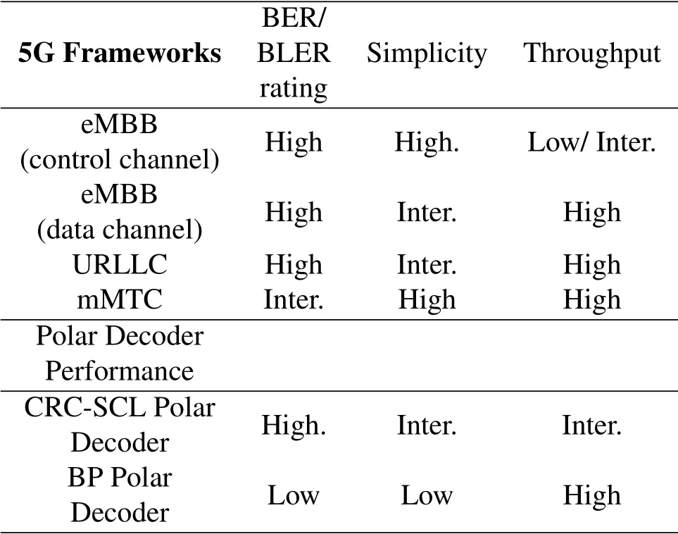
Table 1.Requirements of a FEC method on 5G frameworks.
Sections of the manuscript are also constructed according to three major aspects of any error correction code scheme,BER/BLER performance ratings,complexity of the operation and possible throughput of the decoder.After introducing the polar codes and belief propagation based decoding of polar codes in section II,section III focuses on BER/BLER performance of the BP polar decoders.Since it is the most studied part and include high novelty name is chosen Art of BP Polar Decoding for this section.Major drawback of the BP polar decoder is its complexity over CRC-SCL decoder that is a popular FEC,nowadays.Section IV mention decreasing the complexity of BP decoders.Although,BP based decoders are fast,it can be faster.In this scope,Section V gathers the studies about increasing decoding speed of BP based po-lar decoder in other terms methods to lead faster convergence are presented.Section 6 includes the other working areas that are the subject of BP based polar decoder like how to choose frozen bits more appropriately,what kind of error types are exist,what type of adaptive strategies can be followed to enhance decoder and how the hardware implementation of BP polar decoder is accomplished.Manuscript closes to end with the introduction of open research challenges to guide researchers and conclusion of the tutorial.
II.POLAR CODES
In this section,we will give information about polar encoder and decoder logic units and derive the belief propagation algorithm formulas for the decoding of polar codes.
2.1 Polar Encoder
Polar encoder kernel unit is depicted in Figure 1.From Figure 1,we can write that
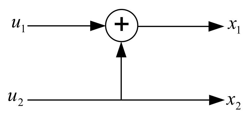
Figure 1.Polar encoder for N=2.

For the information word u=[u1u2],after polar encoding operation,the obtained codeword is x=[x1x2]wherex1=u1⊕u2andx2=u2.The relation between x and u mathematically be expressed as

where GNis the generator matrix forN=2 and it is equal to
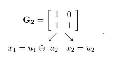
The generator matrix of the polar code is an involutory such that

Calculation of polar code generator matrix can be defined as GN=BNF⊗nwhereand⊗nstands for thenthKronecker product of a matrix.BNis the permutation matrix also known as bitreversal matrix that is calculated as BN=RN(I2⊗BN/2).I2is the identity matrix,and B2is calculated as B2=I2where RNis the permutation operation,for instance,R4maps the input{1,2,3,4}to{1,3,2,4}.
2.2 Belief Propagation Based Decoding of Polar Codes
BP algorithm is proposed by R.G.Gallager[14]for the first time in 1962 while Tanner graph representation of this algorithm is proposed by R.M.Tanner[6]in 1981.BP decoding scheme is based on message passing between check nodes and variable nodes placed on the right and left hand side of factor graph.For x=uGNencoding operation,the kernel encoder and decoder units are shown in Figure 2.
Leta,b,c,dbe the random variables and assume that the bits and are transmitted through a discrete memoryless channel.At the decoder side,the flow of the signals change direction as shown in Figure 2 whereandare the outputs of a discrete memoryless channel,i.e.,they are the received bits whileandare the estimated data bits.In polar codes,GNequals,so the encoding and decoding operations can also be interpreted as in Figure 3.

Figure 2.Polar encoder and decoder units for N=2.

Figure 3.Alternative demonstration of polar encoder and decoder for N=2.

Figure 4.Factor graph representation of G2.
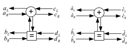
Figure 5.Signal flow diagram for BP polar decoder.
The Figure 2 and Figure 3 can be combined as in Figure 4 where an iterative structure can be used with BP decoding algorithm.By this way,factor graph representation of kernel polar encoder/decoder is constructed to be able to allow from both left and right direction propagation of information.
Or using parallel arrows,factor graph will be modified as shown in Figure 5 for better understanding.Lstands for left propagation whileRstands for right propagation.
Leta,b,c,d,w,x,y,zbe the random variables,andpx(x1)=Prob(x=x1)be the probability mass function.Ifz=x ⊕y,then

Let’s define the operator⊙,ifw=x ⊙y

Then,we can write that
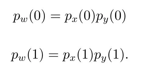
Now let’s try to calculate likelihood ratio(LR)ofaL

From Figure 5,we can write that
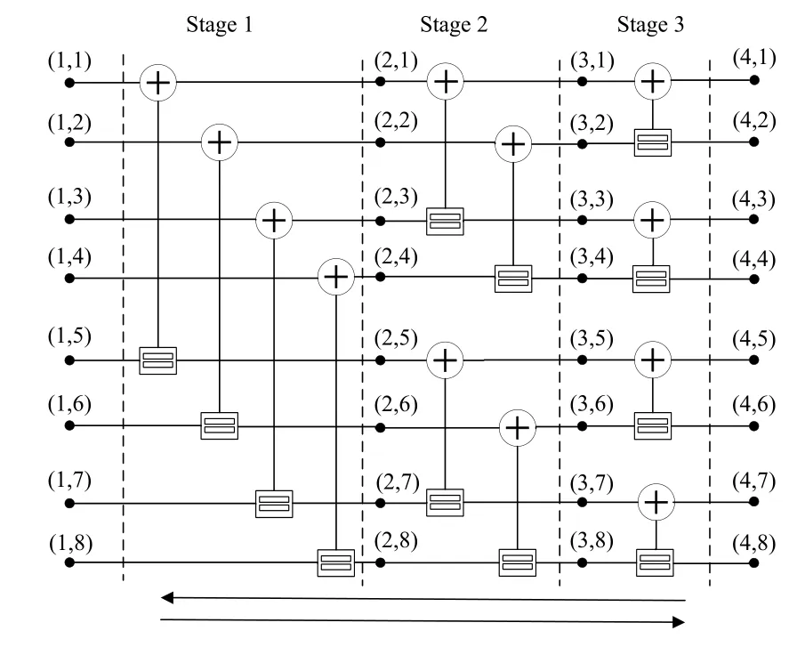
Figure 6.Encoder and decoder structure for N=8.
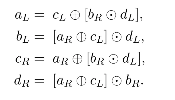
We can write the probabilities foraLas
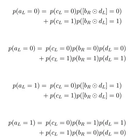
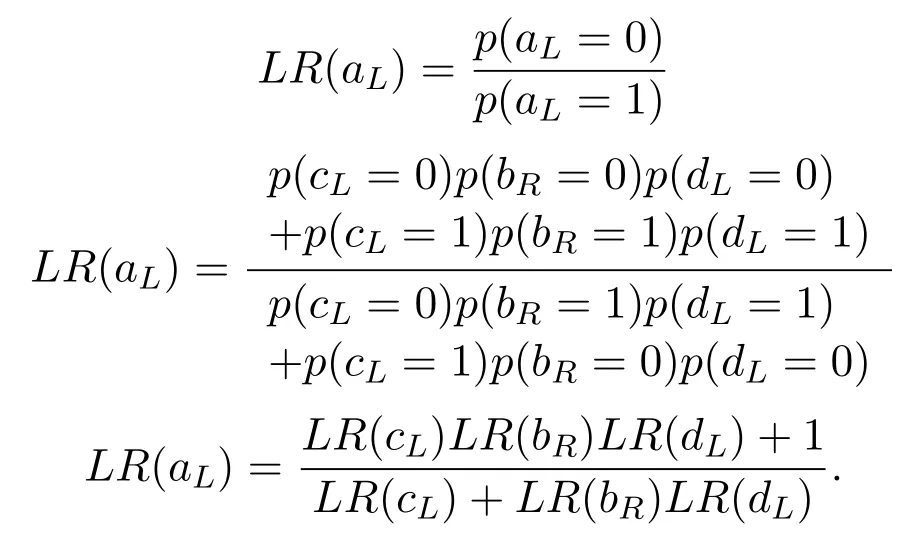
With a similar approach,using

we calculateLR(bL)as
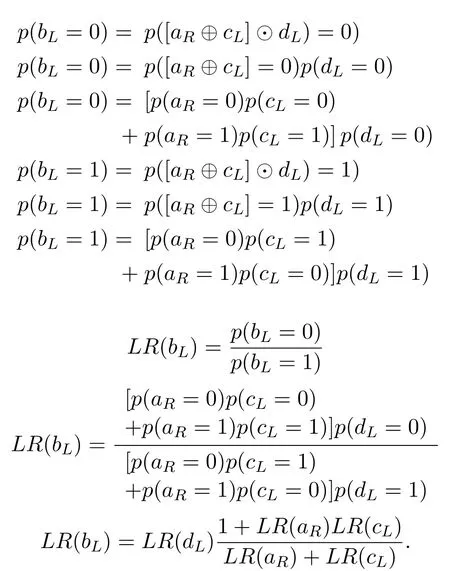
In a similar manner,using

we can calculateLR(cR)as
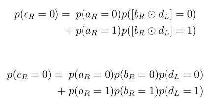
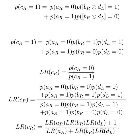
In a similar manner,using

LR(dR)can be calculated as
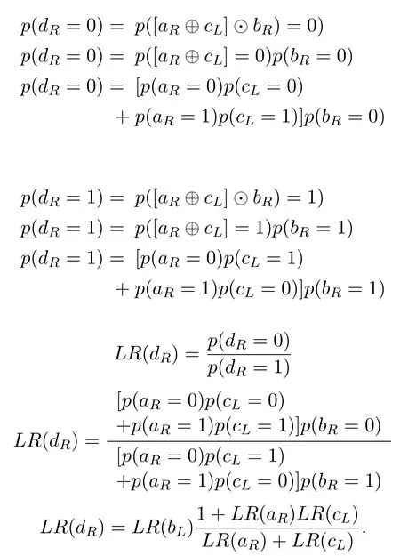
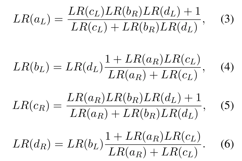
So far,derivation of likelihood ratios(LLRs)of propagating messages for a simple BP based polar kernel decoder have been made.LLRsfor the left and the right propagating messages are derived separately for each node.Hence,the equations(3)-(6)are obtained.
Polar encoding and decoding operations can be graphically demonstrated as in Figure 6 via factor graph formation.The factor graph of G8,N=8,in Figure 6 consists of basic computational blocks(BCB),i.e.,processing elements(PE)and each stage of graph includes PEs where iterative operations are performed.As noticed number of stages,determined by log2N.
Generalized version of the kernel polar decoder,PE,contains two inputs and two outputs as shown in Figure 7 whereRrepresents the messages propagating rightward whereLrepresents the messages propagating to the leftward.The propagating messages can be represented in terms of likelihood ratio by adding the indexes representing the stage based structure and the nodes of the decoder into account.
The propagating messages for any PE on a factor graph like in Figure 6,use equations(7)-(10)which are adapted from the derived likelihood ratios in(3)-(6)of the kernel iterative decoder unit of Figure 7.
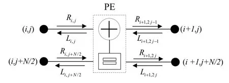
Figure 7.Basic processing element(PE)of BP based polar decoder.
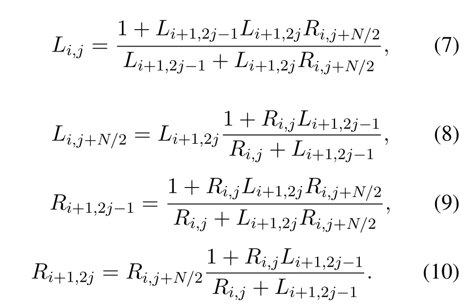
which can be expressed as
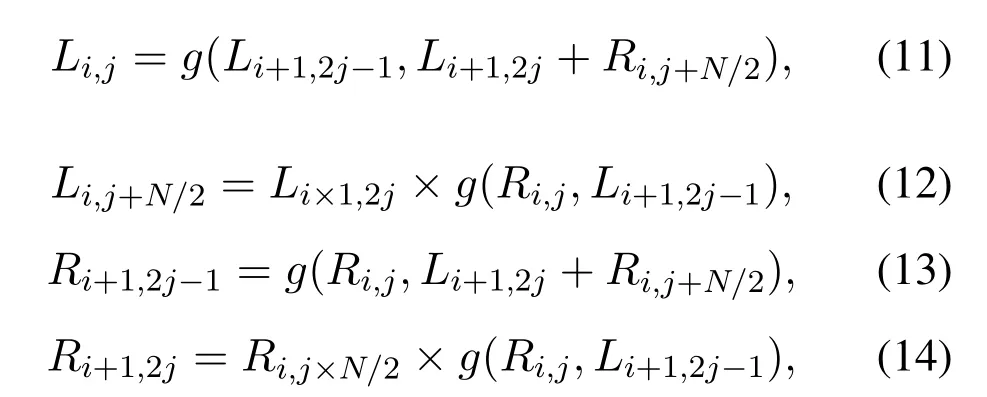
and whereg(.)function defined as

Before the BP algorithm is started,initial values are assigned to propagation messages.First of all,the likelihood values are calculated by using information that comes from the communication channel.Calculated likelihoods are denoted byLn+1,jwherenequals to log2Nandjrepresent the nodes in any decoding stage.The paremterjis an integer satisfying 1≤j ≤N.Channel likelihood values are calculated by using

wherep(yi|xi)is the channel transition probability for channel inputxiand channel outputyi.Secondly,pre-determined values should be assigned to frozen nodes whose indexes are specific to the designed polar code.The indexes of frozen bits are determined by polar code construction methods.R1,jis used to express frozen node values.InR1,j,indexes that stands for the information bits are simply assigned to unity.Once the initial values are set,then BP decoding can start.When theMiterations are completed,a hard decision is made according to

The implementation of(7)to(10)requires significant amount of hardware resource and results in latency for BP decoder.To alleviate the large complexity and latency issues,logarithmic version of the formulas(7)to(10)are considered for hardware implementations,i.e.,multiplications are converted to summations while divisions are converted to subtractions.Theg(.)function defined in(15)is expressed in log domain[15]as

for BP decoding of LDPC codes.Additionally,initial conditions and likelihood calculations can be expressed in log domain.The log domain equivalent of(7)to(10)can be written as
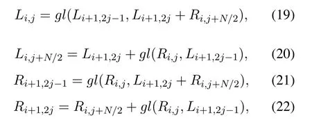
where thegl(.)function is defined in(18).
In this manuscript,polar code with codeword lengthNandKinformation bits is denoted asP(N,K).
III.ART OF BP POLAR DECODING
Proven potential of BP based decoding algorithms motivated researchers to enhance BER/BLER performance of BP polar decoder.As indicated in Table 1,BP polar decoder has poor error correction capability.However,BP based iterative decoding of LDPC codes gives good results.BP based polar decoder has a potential in term of throughput when compared SC based polar decoders.Novel approaches are developed in the last decade to use BP algorithm on polar codes with high error correction capability.We classify these novel approaches into nine parts and explain in detail.
3.1 Scaled Min-Sum BP Polar Decoder
Hardware implementation of the decoders is a prevailing topic in coding theory.Usually,logarithmic approximations of the error correction codes are developed to lower system complexity and power consumption.Thus,Log-likelihood ratio(LLR)is used to implement log domain equivalent of BP algorithm.Working with LLR values simplifies the operations on decoder,but,it usually causes degradation in BER performance due to approximations.Motivated by this,improved version of the log domain BP algorithm called Scaled Min-Sum(SMS)decoding algorithm is proposed[16]as
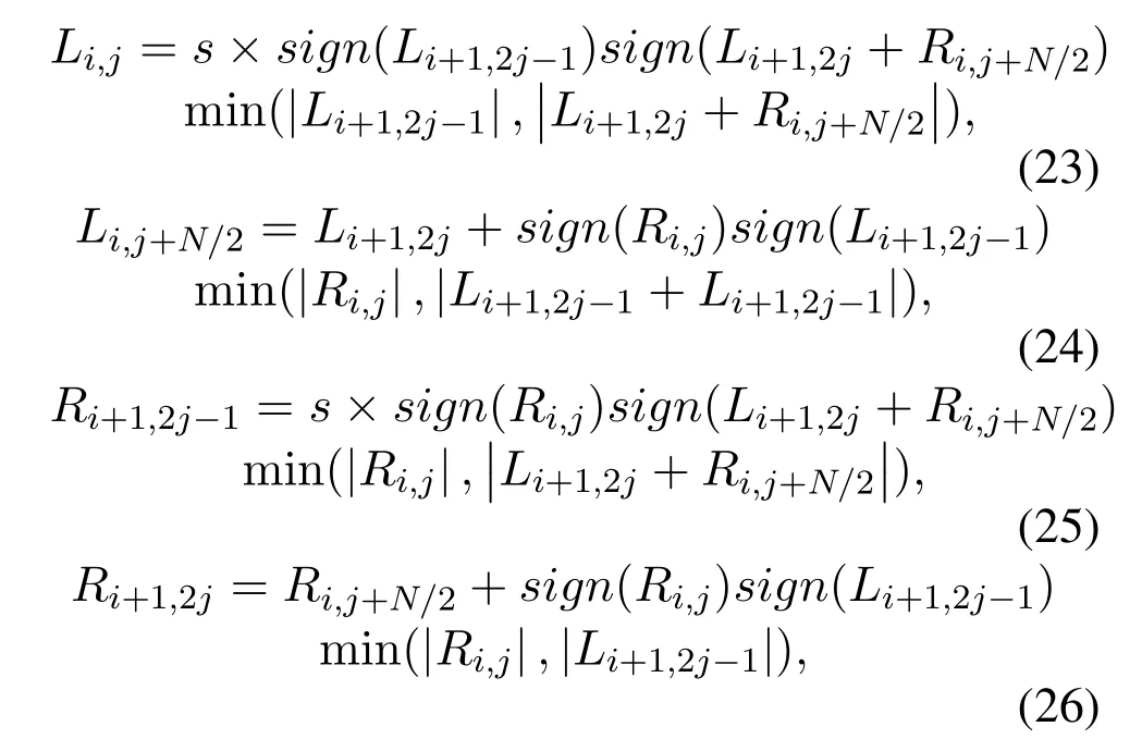
where scaling factorsis added to equations to compensate the performance loss.Simulation results show that with scaling factors=0.9375,2.2 dB performance improvement is obtained when compared to the classical BP algorithm employing polar codeP(1024,512)on AWGN channels[[16],Figure 2].Although BER performance improves,complexity(logic gate count)and the latency also increase.Authors in[16]solve the latency problem.SMS based BP decoding algorithm which has the same gate latency of MS BP decoder is further developed by keeping in mind that the maximum clock frequency of overall hardware implementation is determined by the highest critical path delay of a block.SMS BP method is used as standard decoder[17–25]in many studies.Furthermore,PE of SMS is optimized using high speed parallel prefix.Using Ling adder instead of carry ripple adder is proposed[23]where logic gate delay of a PE is decreased from 2.594 ns to 0.959 ns[[23],Table 2].
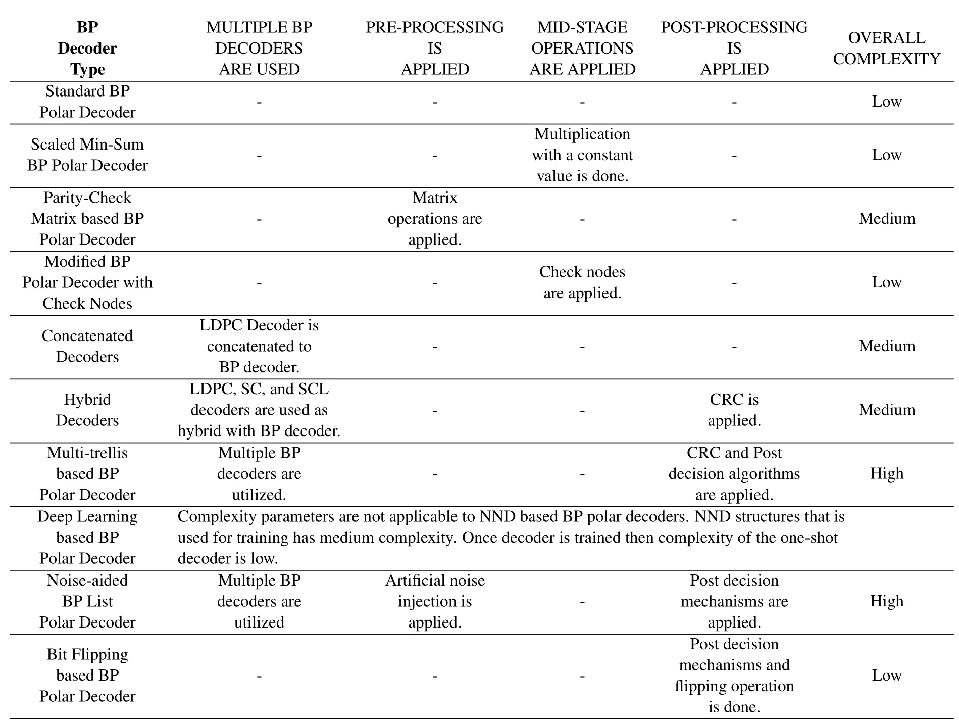
Table 2.Complexity comparison of the major BP polar decoder types.
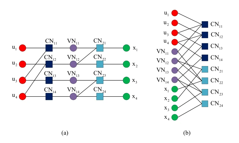
Figure 8.(a)Variable and check nodes for G4.(b)Sparse Tanner graph of BP polar code,G4.
Alternative to SMS BP decoder,three different approximations of(7)-(10)are presented[26].Better BLER performance is achieved for all approximations over MS BP decoder with a margin of increasing complexity.In[27]renew min-sum(RMS)BP decoder,which can be considered as an alternative to SMS BP,is introduced.
In summary,it may not seem practical to add a coefficient of multiplication to the equations to improve the output of the convergence method to avoid operations such as multiplication and division.However,this multiplier coefficient is applicable when it is an exponential multiple of two as in SMS BP,and the error correction performance is remarkable.
3.2 Parity-Check Matrix Based BP Polar Decoders
In[28]the authors showed that parity check matrix,H of a polar code can be obtained from the columns of the generator matrix G corresponding to the locations of frozen bits.Since the parity check matrix H has high density,it is not feasible to apply BP decoding using the parity check matrix.Instead,H matrix is used for early detection/termination to stop the iterations[29].Meanwhile,an adaptive H′matrix construction is presented[30]to increase convergence accuracy.Adaptive-parity check matrix construction steps can be outlined as:
•First calculate the absolute values of received LLRs.
•Then sorting the values of the previous stage in ascending order,the sequence y is formed.
•A vector B of lengthN −Kdenoting the indices of least reliable bits of y is generated.
•HBis constructed from columns of H using B.
•Gauss elimination is applied on HBto reduce the matrix to be an identity matrix.
•New matrix H′is formed.
With this new H′matrix,BP decoding shows better performance in terms of BER compared to the one obtained with SCL.However,complexity increases due to adaptive matrix construction.Operations like absolute value calculation,sorting,Gauss elimination for each received codeword aren’t feasible for long length codes.An improved version of[29]is given in[31]where the proposed method provides efficient memory usage and reduces the latency such that overall latency is reduced by 19%-23.5% and memory usage is lowered by 4.6%-17.6%.A simpler parity-check matrix based BP decoding algorithm is proposed[32].The idea of using the parity check matrix H in BP decoding is due to fact that the H matrix can be represented via sparse factor graph as shown in Figure 8b.
Factor graph obtained from the H matrix contains check and variable nodes as depicted in Figure 8 whereCNi,jandV N1,jare check nodes and variable nodes,respectively.To improve the reliability of propagating messages in factor graphs,variable node messages are multiplied by the corresponding variable node messages obtained in the previous iteration,and in[32]it is shown that this idea achieves 1-2 dB improvement compared to the standard BP decoding.Besides,average number of iterations is decreased by 10-25 when compared with the standard BP decoding even though no early detection method is applied.
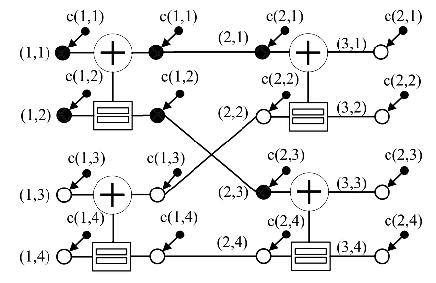
Figure 9.Factor graph representation involving frozen and information check nodes for N=4.
There are two different approaches presented in this subsection.The first method is not applicable at high code lengths because it has to do matrix transformations on the channel outputs every time.In the second method,it has been shown that the error correction performance is increased on the BP polar decoder whose factor graph structure has been changed.Although the presented method shows improvement,it has a limit and is not in a position to rival LDPC or SCL decoders.
3.3 Modified BP Polar Decoder with Check Nodes
Factor graph of a polar code is modified such that it includes frozen and information nodes in addition to the check nodes[33]to further enhance the decoding performance.Additional nodes are depicted in Figure 9,as frozen and the information check nodes,denoted byc(i,j),are shown in red and white,respectively.
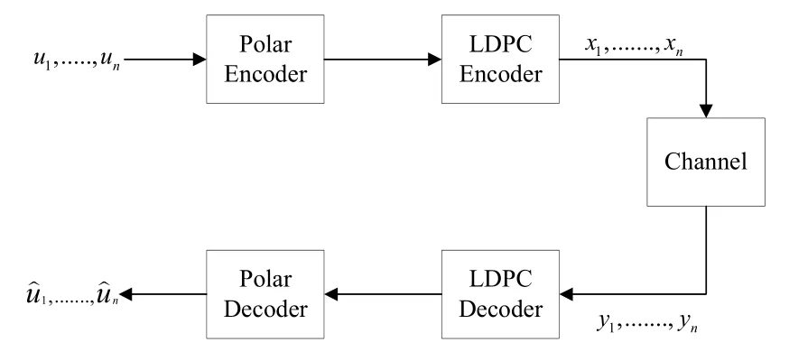
Figure 10.Concatenated code structure involving polar and LDPC codes.
Likelihood values of the frozen nodes shouldn’t be updated during iterations.Otherwise,less reliable likelihood values will be obtained for the frozen nodes that causes performance loss.The added information nodes improve the reliability of the messages coming from the predecessor information nodes.It is seen that the modified BP decoder utilizingP(2048,1024)achieves 0.5 dB gain over conventional BP polar decoder with 60 iterations at 10-6 BER.
In brief,the check node,which is easy to apply,can be used as a mid-stage process.Although its effect is not high alone,it will be beneficial when used together in other methods.
3.4 Concatenated Decoders
Concatenated polar codes often increase the decoding complexity,but their error correction benefits are quite high.The best examples of this are the CRC aided polar codes[13]and parity-check-concatenated polar codes[34].In both examples,relatively small size codes were used before the polar code.Thus,their error correction performance has increased significantly.Another feature of the two examples mentioned is that they both use successive cancellation algorithm as polar decoders.In this scope,first concatenated decoder involving BP polar decoder is proposed in[35]where the RS code is used as the outer code and the polar code is used as the inner code.The probability of word-error in polar codes decays sub-exponentially and it is a function of block length.Using a high rate RS code as the outer code,it is shown that the probability of word-error,Pe,decrease in an exponential manner.
Asymptotic performances of the concatenated code structures involving polar codes are considered[35].Moreover,concatenated decoders for practical communication systems that involve polar codes and LDPC codes are studied in[36–38].LDPC codes achieve Shannon’s capacity limit and can be decoded by using BP algorithm so these properties make them good candidate to concatenate with BP based polar decoders.Moreover,they are defined in communication and broadcast standards like Worldwide Interoperability for Microwave Access(WiMAX),10GBASET 10 Gbit/s(1,250 MB/s)Ethernet over unshielded twisted pair(802.3AN),Digital Video Broadcasting— Second Generation Terrestrial(DVB-T2),Digital Multimedia Broadcast-Terrestrial/Handheld(DMBT/H),and Digital Terrestrial Multimedia Broadcast(DTMB).
The work presented in[35]uses polar codes as outer code and LDPC codes as inner code as depicted in Figure 10 where u,x,y,represent user data,encoded data,received data and estimated data,respectively.LDPC codes have good waterfall characteristics,on the other hand,they suffer from an error floor.It is known that error floor is a common problem of modern codes decoded using BP algorithms[39].Concatenating polar codes with LDPC codes,the error floor problem of the LDPC codes is alleviated.The proposed method is implemented for optical fiber links,with data rates up to 100 Gbps in optical transport networks.The concatenated system involving RS,LDPC and BCH codes has been standardized for optical transport network where the code rate is specified as 0.93,and both polar and LDPC codes are decoded using soft decision based BP algorithm.
It is shown in[[36],Figure 4]that the concatenated structure involving polar and LDPC codes can be a good candidate for optical transport network standard requirements in terms of BER performance and interchangeable code-rates.A hardware implementation of concatenated polar-LDPC code structure[36,37],is presented in[40].A similar study is done in[41]for polar-LDPC cascaded structure with a slight modification of[36,37].At the junction of two decoders’factor graphs an influence factor ofαis employed.Influence factor is multiplied with soft message that comes from polar decoder.Effect of differentαvalues is studied in[41]and it is seen that better BER performance is observed such that defined factor adjusts the proportion of two decoders.
An improved concatenated scheme involving inner polar codes and outer LDPC codes is proposed in[42]which is illustrated in Figure 11.Improvement is achieved for two different BP decoding algorithms.One of them is conventional flooding BP algorithm,and the other is soft successive cancelation(SCAN)BP algorithm.The SCAN BP[43]can be considered as a sequential BP that decodes the bits sequentially as in SC opposing the parallel nature of BP.LDPC coding is applied to non-polarized(intermediate)bits channels and corresponding bits as outer code.Three channel types can be defined considering the threshold valuesδ1andδ2as
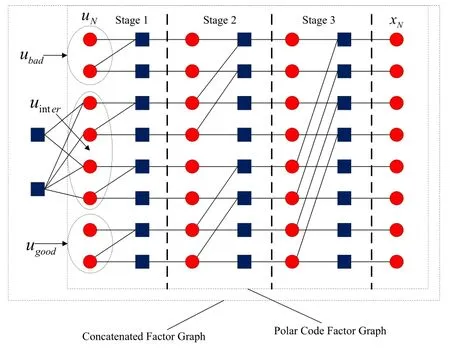
Figure 11.Factor graph for improved BP decoding algorithm.
•good channels,ugood,
•bad channels,ubad,
where 0< δ1≤δ2<1 and wherestands for Bhattacharya parameters that is accepted as an upper bound for the maximum probability of transmission errors[2].
In[[42],Figure 4],it is shown that the average number of iterations for the improved BP algorithm is larger than the average number of iterations for the simple flooding BP.However,improved BP algorithm has less average number of iterations for the concatenated structure involving polar and LDPC codes under soft cancelation,i.e.,SCAN,decoding.It is obvious that the success of improved BP with SCAN decoding comes from its similarity to SC decoding.Because intermediate capacity channels,in other words nonsuccessfully polarized channels,are decided by applying Bhattacharya based estimation in finite lengths as presented in[2].Thus,intermediate channels can be selected more accurately if a suitable polar code construction method can be found for flooding BP algorithm.
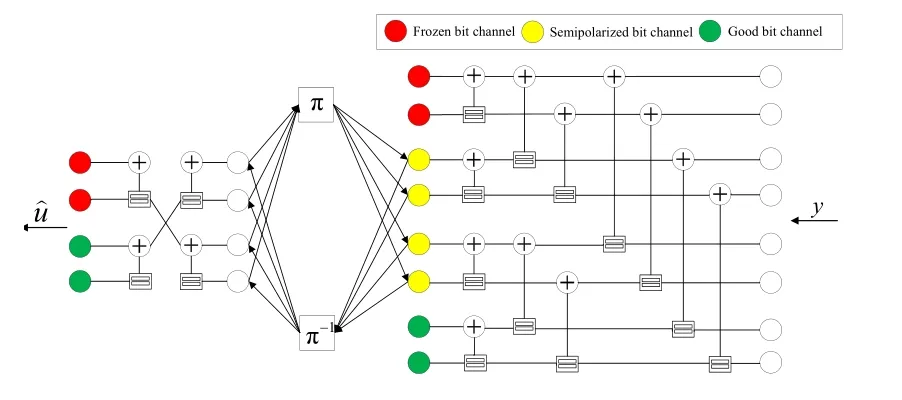
Figure 12.Shorter length polar codes are used as auxiliary codes for larger length polar code.
Another concatenated structure is presented in[44]named as an auxiliary code in which LDPC part of the structure is improved.Short length LDPC codes are designed using the scattered extrinsic information transfer,i.e.,EXIT charts.The proposed design achieves 0.4 dB improvement compared to conventional BP while 0.2 dB improvement when compared to the work in[42].
As we stated before,LDPC code is used for intermediate bit-channels having neither high nor low capacity values,to achieve improvement for the concatenated code performance[42].On the other hand,intermediate channels are sorted according to their reliability,and LDPC codes are utilized for these sorted intermediate channel bits[45].A bit mapper is employed between LDPC and polar code factor graphs to accomplish the sorting operation.Sorting is done according to leaf set sizes of the intermediate channels.Since Bhattacharya parameters can be considered as an upper bound for maximum probability of error,the Bhattacharya parameter based selection does not show its optimal performance for BP decoder.In[37],it is shown that leaf set size is directly proportional to the protection rate of a bit channel.As a result,the suggested structure[45]has 0.3 dB gain over the study with EXIT charts in[42]and 0.5 dB gain over pure BP scheme at 10−5BER.
In[46],bit channels that have the same leaf set sizes are sorted in descending order based on Bhattacharya parameter.After sorting,the number of bit channels are selected to be used for the outer LDPC code.When compared these similar studies of[42],[45],and[46],it is obvious that leaf set size is an important parameter to BP decoder’s performance.
Polar codes also can be used as auxiliary codes for the structures decoded using BP based algorithms.Arıkan in[2]stated that polar codes are constructed in a recursive manner using the general units.This allows the construction of large length polar codes[47]as a concatenation of several smaller length codes.In[[47],Figure 2],code generation via concatenated code structures is presented.A concatenated structure involving one short auxiliary polar code,an interleaver and an inner polar code is provided[48].Interleaver is used to make two polar encoder/decoder’s LLR values statistically independent of each other.Auxiliary polar code is used to protect semi-polarized information bits.The factor graph for the auxiliary polar code is given in Figure 12 where represents likelihood ratio of received data andrepresents estimated data.Two polar code is connected to each other with interleaver/deinterleaver(π/π−1)blocks.
A different structure involving one auxiliary and two inner polar codes is designed in[48].The designed system achieves a gain of 0.3 dB at BER of 10−5over conventional BP polar decoder.
A joint decoding algorithm based on BP sparse code multiple access(SCMA)detection and polar code decoding presented in[49]has 0.2 dB gain over BP decoder performed at 10−4BER.The proposed method combines the factor graphs of the two methods so that the probability information between them can be circulated.Thus,probability,soft information,can have higher precision and decoder can converge faster.
Polar code is concatenated with convolutional codes rather than a linear block code for the first time in[50]to open a new research are in the topic.
G.David Forney Jr.showed that by utilizing concatenated codes,the Shannon limit can be achieved.A simple internal code operating directly on the input and output of a communication channel can achieve a moderate error rate at data rates close to the Shannon limit.An outer code used before and after data enters the internal code can further reduce error rates by using a powerful but less computationally complex algorithm.This approach is followed in many IEEE standards and earned him The 2016 IEEE Medal of Honor award.The researchers who followed this path,as described in this subsection,presented many concatenated codes involving polar codes.The most important of these can be seen as the coding of intermediate channels with LDPC code,which is seen as the weak point of relatively short polar codes.We think that there this area of study is promising and that studies can continue in order to achieve better results.
3.5 Hybrid Decoders
Two different types of hybrid design are studied to make BP based polar decoder preferable among upcoming 5G frameworks.First type of hybrid decoder allows decoding process to be more flexible such that only one type of decoder performs the decoding when the other one fails.A hybrid decoding approach involving both BP decoding and SC decoding is presented in[51,52].In this method,whenever BP decoding fails SC algorithm is performed.This method achieves 0.2 dB improvement over basic BP based polar decoder.
Following the introduction of BP-SC hybrid decoding approach,BP-SCL hybrid decoding is offered in[53,54].It is clear that BP-SCL hybrid decoding has more advantages over SC and SCL algorithms in terms of decoding latency.To limit the number of iterations,CRC is unified with BP-SCL.If CRC is not satisfied for maximum iteration number,M,on BP decoder,then SCL decoding is performed.Hybrid structure employing the polar codeP(4096,2048)achieves the same BER performance as that of the SCL decoding with list lengthL=32.It is observed that the hybrid structure has lower latency after certain SNR values[[53],Figure 5a].
The decoder used in 5G NR can be considered as the second type of hybrid decoder.LDPC codes are used as to correct the errors on data channels,while polar codes are considered for the protection of control channel information.For the decoding of LDPC codes,BP based LDPC decoding algorithms are employed,on the other hand,polar codes are decoded using low complexity and high bit-error performance CRC-aided SCL algorithm.This implies that two separate decoders are to be utilized in eMBB communication services.Moreover,time division duplexing(TDD)is going to be used to send the control and data channel information sequentially.However,if the polar codes are decoded by a BP based algorithm,both LDPC and polar codes can be decoded with a single hybrid.The hybrid decoder design reduces the overall complexity of the system using the TDD structure.There are two studies[55,56]introducing such a structure.When the results of the studies are evaluated,it is seen that the combined polar code and LDPC decoders are promising for future studies.Both polar codes and LDPC codes can be decoded with the same style BP type decoder.Guiding polar codes,to be decoded by BP algorithm with high error correction rates,is one of the main purposes of this article.We aimed to draw a road map for researchers by presenting all the studies in this field.
3.6 Multi-trellis BP Polar Decoders
It is shown in[4,57]that the Tanner graph for BP decoding operation can haven!different representations obtained by different permutations of thenlayers of connection named as multi-trellis.In this manner,two of the stage permuted representations of original factor graph,G8,are demonstrated in Figure 13.It is shown that swapping stages within a polar factor graph doesn’t change encoded codeword when information and frozen bit places stays same[58].

Figure 13.Permutations of trellis structure for G8.
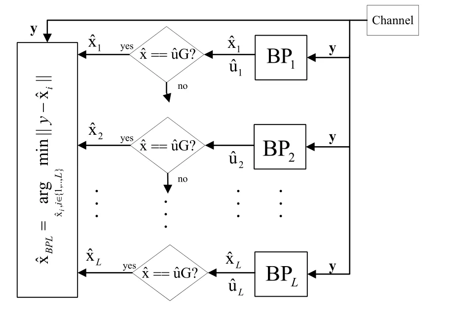
Figure 14.The block diagram of the multi-trellis belief propagation list decoding algorithm utilized for polar codes.
Multi-trellis approach is used to overcome error floor problem as explained in[59].Whenever the decoder fails,a different permutation of the trellis structure is used.In another study,permuted factor graphs employing early stopping criteria are used for BP decoding of polar codes[60].If the decoding operation fails utilizing a factor graph,then another factor graph,obtained permuting the original factor graph different than the used one,is employed for the decoding operation.Multi-trellis decoding approach decreases the average number of iterations for the BP decoding of polar codes,typically an iteration number ranging from 200 to 105would be enough before the termination of decoding operation.It is seen that 0.4 dB gain at BER 10−6over for SCL withL=32 is achieved,however,CRC aided SCL is still better than the proposed method[[60],Figure 4].
The multi-trellis approach of[60]is further improved by selecting permuted factor graphs deliberately in[61].A method is proposed to choose the better permutations in case of decoding failure for the original factor graph.It is reported in[61]that 0.2 dB improvement is achieved at BLER 10−4forM=10,whereMis number of pre-defined permutations,when compared to the method in whichMpermutations are selected randomly.If a larger value is used forM,such as 32 and 128,even more improvement is achieved.
The main advantage of BP decoding algorithm utilized for polar codes is its parallel structure enabling high throughputs when sequential algorithms SC/SCL are considered.However,in the studies[60,61]different permutations are utilized in a sequential manner until a correct codeword is obtained.As the number of permutations,Mincreases the throughput of the multi-trellis BP decoding operation decreases.A BPlist(BPL)with multi-trellis decoding algorithm is introduced in[62]to benefit from the parallel decodable property of the BP algorithms.It is reported in[62]that the performance of the proposed algorithm is approximately 0.5 dB worse than that of the state of the art SCL decoding algorithm at 10−5BLER.The block diagram of the BPL decoding algorithm is depicted in Figure 14.It is seen from Figure 14 that parallel decoders and G-matrix based early detection algorithm run at the same time by using same channel output i.e.y.Decoders use different permutations of the original factor graph and they are constructed usingkcyclic shifts of the original factor graph where 1< k ≤L.The outcomes of the decoders asandare compared to channel output in terms of Euclidean distance,and the minimum of them is chosen to be output of BPL decoder.In addition,in[62]the authors use a different polar code construction method called RMPolar codes,leads better BER performance with BPL decoding algorithm.
The detailed explanation for the RM-Polar codes can be found in[62].One disadvantage of BPL decoding algorithm is that as the number of parallel decoders and number of iterations increase,the complexity of BPL algorithm becomes higher than the complexity of the SCL algorithm.However,due to its parallel decodable property,BPL algorithm is a more promising technique than the SCL algorithm if latency has paramount importance on any system.Another advantage of the BPL decoding algorithm is,its soft input soft output structure,and,it can be used to construct joint forward error correction systems with other soft-output detection and decoding algorithms.Further improvement on BPL is achieved in[27]by utilizing RMS BP decoder in BPL structure.
Multi-trellis approach is also analyzed in terms of frozen variable node numbers in[58]for different rates of polar codes.As expected,as the number of frozen variable nodes increases the decoders show better BER performance.Frozen variable nodes are visualized in Figure 17a with black color.Decoders with different trellis structure have different number of frozen variable nodes.An adaptive approach is studied in[63]to further improve the performance of the BP based decoders.As the coding rate changes,the best permutation is chosen according to frozen variable node number.When a list of decoders constructed using different permutations are considered,the decoder having the permutation with maximum value is chosen as first decoder[63].Some recent studied are introduced to find better(leads to faster and accurate convergence of the BP decoder)factor graphs in[64–66].An improved variant of the multi-trellis decoder that allows partial permutations of factor graph of the decoder is presented in[67].Aim of the partial permutations on the trellis structure is to retain the information of the variable nodes that do not change.It is also shown that partial permutation is more effective on oscillation errors.
Thanks to construction of polar codes it is easy to utilize multi-trellis approach in encoder and decoder.By using multi-trellis approach during decoding provides alternative convergence records and convergence speed thus may lead to better decoder performance in terms of latency,BER/BLER and throughput.Thus,working with this option leads to better error correction performance if it is set correctly.If it is constructed correctly,the mentioned advantages of multitrellis structure can be used.However,due to its nature,it does not seem to be possible to reduce both the complexity and the latency.This situation prevents it from being used for further studies.
3.7 Deep Learning Based BP Decoding of Polar Codes
As a general decoding method for linear codes,it is shown that BP decoder can be a subject of deep learning.Deep learning methods are shown to be useful in image and video processing based object detection and tracking,and marvelous outcomes are achieved in machine translation that provides automated translation from one language to another.Moreover,significant outcomes in speech processing,and recognition are observed.Deep learning methodologies are also used in error correcting codes to achieve the Shannon’s capacity.The first example of BP based decoding of error correcting codes aided by deep learning is presented in[68].For the error correcting code,BCH codes are chosen and BP based decoding of BCH is taken into consideration.In this approach,for the training of the system using the deep learning method,a data set of 245codewords must be used for short length BCH(63,45)code.Huge amount of codewords make the system training hard to implement.This drawback is overcome by assigning weights to the edges of BP decoder in[68].These edges are trained and multiplicative weights are calculated.By this approach,much less training data is sufficient to observe reasonable decoding performance.As a result,0.4 dB gain is achieved at 10−2BER for a BCH(63,36)code over original BP based decoder.Modification on multiplicative weights that are assigned to edges of a Tanner graph is done in[69]converting them to additive offset parameters.Hardware consuming multiplication is reduced and 0.1 dB gain is achieved over the method presented in[68].However,the presented work is still cannot be accepted as a full-scale deep learning approach that cares which nonlinear activation function is going to be used,how many hidden layer should be set,what is appropriate loss function and etc.The study in[70]focuses on decoding using a complete deep learning procedure.A deep learning step for channel coding of this method is demonstrated in Figure 15.
Deep learning system consists of an encoder,a virtual channel that creates noisy versions of transmitted codewords,and a neural network decoder(NND).In a NND,input,hidden and output layers are sorted from left to right.For example,there are three hidden layers in Figure 15.Unlike an iterative BP decoder,NND structure finds estimates of transmitted codewords without any iteration,and this approach is called as one shot decoding.NND structure has advantages over original BP decoder in terms of decoding latency and BER performance,however,large number of training data sets creates a serious drawback for the training process.
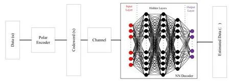
Figure 15.A complete deep learning setup.
Number of training data is chosen ranging from 210to 218for polar codes where the code length is 16 and rate is 0.5[70].As the training data amount increase,the performance of NN based decoder’s approaches to MAP decoding.Although training complexity increases exponentially as the code length increases,it is important to state that once a NND system is trained,the one-shot decoding becomes possible.Keeping in mind this fact,partitioning is applied to be able to decode long polar codewords using deep learning based methods[71].Long polar codewords are divided into smaller words that can be trained relatively in short time.Smaller NND structures with at most 8 information bits and withN=128 polar code are decoded.Similar performance is achieved with SC and BP based decoders,however,one-shot decoding became possible providing low latency.A similar approach introduced in[72]named as neural SC decoding is used for SC decoding of polar codes.Small neural networks are connected to each other to cover the logic of SC decoding.Overall 42.5%reduced decoding latency is achieved forP(128,64)
In section 3.1,An SMS BP polar decoder is proposed utilizing equations(23)-(26).A scaling parameterαis employed for the right and left propagation message equations and the value 0.9375 is shown to be optimum for the better performance.Inspired from parameter scaling,applying multipleαto different nodes during different iterations is studied using NND in[73]where hidden layers of NND are constructed using Tanner graph of BP polar decoder.Tanner graph of BP polar decoder uses log2Nstages for each iteration,and these stages are used twice as the left and right messages propagate.One iteration of BP polar decoder is configured to be used as hidden layers by doubling stages,and putting one to tail of another.If a BP polar decoder withkiterations is converted to NND structure,then 2k+1 number of hidden layers are created[73].Training is accomplished to find differentαiparameters,whereiis the hidden layer index forP(64,32).For instance,BER performance of the NND structure increases when it is created for BP decoder with 7 iterations.However,it is important to state that the structure with 6 iterations has very close BER performance compared to NND with 7 iterations[[73],Figure 6].A modified version of[73]different than the CRC aided BP based polar decoding[20,53]is proposed in[74].Idea comes from the fact that both CRC and polar codes can be decoded using BP based algorithms.In method,factor graph of CRC is added as hidden layer in front of the hidden layer equivalent of every log2Nstage of BP factor graph a consecutive manner.More detailed information is provided in[[75],Figure 5],and it is seen that up to 0.4 dB BER gain is observed whenP(128,80)is used.A hybrid structure of polar-LDPC decoder based on deep learning is proposed[76]for 5G communication systems.An indicator section is added to deep learning for both decoding schemes.Indicator section enables to use different learning parameters since polar and LDPC encoding operations are done sequentially in the transmitter.Considerable BER gain is achieved for short length codes.
The conventional multi-stage polar BP decoder shown in Figure 6 can be converted to an LDPC-like structure as in Figure 8b.However,its dense graph causes poor performance despite its advantage of latency reduction.Sparse Tanner graph of BP polar decoder is obtained applying pruning techniques on G to get H[77].Performance and throughput gain are achieved using sparse Tanner graphs.Sparse decoding structure is combined with neural networks using deep learning concept in[78].Sparse neural network decoder is constructed for 10 iterations[[78],Figure 3],and trained forP(256,128).Simulation results show that the proposed sparse neural network decoder outperforms MS and SMS polar decoders.
Similar to[73],assigning weights(scaling parameter)to different layers of the NND based BP factorgraph is studied in[79].Assigned weights to adjust the results of the propagating messages help to optimize NND.NND is combined with one-bit quantizer to lead faster convergence on BP decoder.By applying different weights in different layers,the disadvantage of using one-bit quantizer on likelihood values has been eliminated.P(256,128)is utilized for deep learning on BP polar decoder and better error correction performance achieved when compared to MS,SMS[16]polar decoders,and NND structures presented in[68,73,78].
An intelligent post-processing method with the aid of deep learning techniques to achieve better decoding performance is studied in[80].Bit-flipping as postprocessing method is applied when CRC check is not satisfied after maximum number of iterations.Overall,BER/BLER performance of the decoder is slightly improved.
Deep learning methods,focusing on the concatenated polar-LDPC structure,such as back propagation and gradient descent are used to optimize LDPC-BP decoder in[81].Until now,studies on the use of deep learning methods on NND-based polar decoders have been explained.Unlikely,in[82]increasing the speed of the decoder of the deep learning concept is presented.In this study,pre-decide with a NN-based estimator,which decoder to use and,therefore,to avoid the additional decoding latency of the BP decoder with neural network-based on-the-fly decoder method is presented.If the information from the channel is decoded with the BP decoder,it is transferred to the BP polar decoder,or to the SCL polar decoder if it is decoded with the SCL polar decoder.If it is understood by using NN-based estimator that channel output cannot be solved with two decoders,re-transmission is requested.Thus,it is aimed to provide high throughput.
Although NND-based decoders offered with the deep learning concept are promising,there are many steps to overcome.The most important of these steps is to present practical ways of applying the presented methods at medium and high code lengths(N >256).We can already say that the work on methods to train NND structures for high code lengths will continue.
Since deep learning based strategies give one-shot decoding output,their outcomes are valuable for future use.These studies can be used for BP-based decoders as well as other decoder algorithms.Nowadays,the only problem with NND-based studies is that train times are too long for high code lengths.In order to shorten this period,it is necessary to continue with the studies intertwined with the subject of coding theory.
3.8 Noise-aided BP List Polar Decoder
Use of noise in the messages of the belief propagation is proposed to prevent oscillating errors in[63]for the first time.Later on,noise injection in BP polar decoders is considered in[59]to overcome the errors caused by the clipping threshold used to lower complexity of the decoder for LLR values.
Random sign changes are offered in[83]as a postprocessing method to eliminate convergence errors.Apart from these techniques that uses noise aid as a mid-step operation or a post-processing technique,we use noise in the beginning of the decoding operation[84].In this scope,[84]introduces Noise-aided Belief Propagation List(Na-BPL)polar decoder that is one of the best BP based decoder having BER/BLER performance close to the performance of state of the art CRC-SCL decoder.Operation of Na-BPL is simple and it is similar to BPL of[62]in the way of using list concept.Na-BPL decoder diagram is depicted in Figure 16 where it is seen that there areLparallel decoders and each parallel branch is fed with artificially generated noise,n,and after each decoding operation an early detection and termination criteria(EDTC)is applied.The branch that satisfies the EDTC first is chosen for the estimated data.It is also important to state that the factor graphs of the polar decoders are the same of each other(not permuted versions as utilized in[62]),and artificial noise level increases as the list size increases.Na-BPL with list size 32,maximum iteration numberM=200,utilizing G-matrix based EDTC has BER performance which 0.3 dB away from the performance of SCL+CRC-16 decoder employingP(2048,1024).As a result,the proposed approach is a promising candidate to substitute CRC-SCL decoder which is chosen to be used in 5G physical layer as the forward error correction method of control channels.
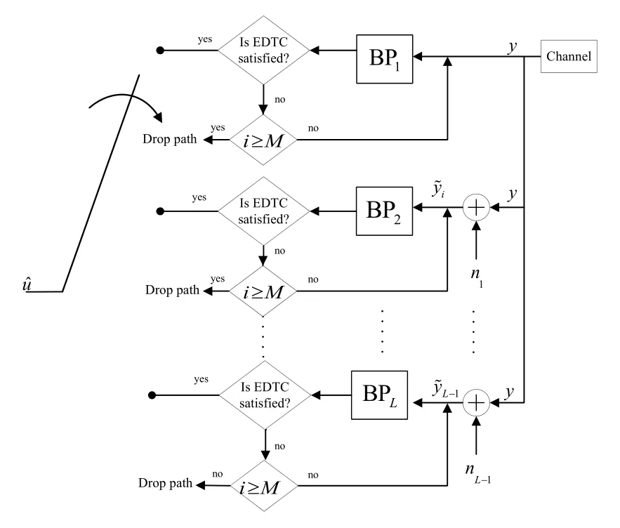
Figure 16.Na-BPL polar decoder design.
The Na-BPL has the same purpose as the BPL(Section 3.6)structure and bit-flipping(Section 3.9).The aim is to randomly find the nodes that will not converge or will wrongly converge before the decoding process begins.Although the structure presented in[84]increases the complexity because of the parallel structure,since the multi-trellis structure is not used,it can be folded and the complexity can be reduced with a margin of decoding latency increment.Better results can be achieved by adding post-processing structures and different early detection structures to the Na-BPL.Studies should also be done on artificial noise characteristics.
3.9 Bit-flipping Based BP Polar Decoder
Random bit changes to handle bit locations with erroneous likelihood value are also studied in bit-flipping.Sometimes,random bit-flipping can lead to better error correction performance.However,performing bitflipping in a controlled manner can result in even better error correction performance[85]for SC polar decoder.Same approach is proposed for the BP polar decoder for the first time in[86].In[87],a modified bit-flipping approach based on BP decoding algorithm is proposed with a different scheme to identify error prone bits.In[88],bit-flipping is used for the LDPC like decoding of polar codes(by using sparse factor graph)resulting in better error correction performance.Further enhancement on bit-flipping based BP decoder is achieved by using multiple bit-flipping sets.In[89],for uncorrected estimations,different flipping sets are applied to achieve maximum likelihood performance.
Instead of performing bit-flipping on random or predetermined sets,bit-flipping sets are determined by using the imitation learning concept with a convolutional neural network-based structure[90].Bit-flipping is applied when CRC is not satisfied after BP decoding.Sets are found by generating training sequences such that useless flipping attempts are avoided.
Bit-flipping is also utilized as an aid to the state-ofthe art belief propagation list decoder.Noise-aided BP list decoder presented in[84]is enhanced by adding flipping feature to the decoder[91].The flipping set length is chosen as 1/4 of the code length.Simulation results showed that despite of the number of iterations that is needed to satisfy G-Matrix based early stopping criteria is higher than the CRC aided BPL decoder,error correction performance is superior.
A method named as advanced BP flip decoding(ABPF)is presented in[92]that shows lower decoding latency and error correction improvement by using joint detection criterion.Joint detection is applied as concatenation of two early detection and termination methods,CRC and observation of consecutive iteration results(OCI).In A-BPF,flipping set generation causes minimal latency through decoding stages thanks to flipping management unit given in the manuscript.The results show that the proposed decoder can achieve a close frame error rate performance to the SCL decoder withL=4 and deliver a throughput of 5.17 Gb/s at Eb/N0=4.0 dB.Furthermore,a generalized BPF algorithm is presented[93].In the generalized form,support for different error types is introduced,i.e.detected and undetected errors.For detected errors,loop sets are defined to handle these errors by bit-flipping if BP decoder fails.On the other hand,a different flipping set construction is studied.By utilizing both of the strategies,generalized BPF achieves SCL-8[13]performance and outperforms the state-of-the-art BPF[86],BP list[62],and SC flip[85]decoding,forP(1024,512).
As a post processing method,bit-flipping is implemented by reversing the error-prone bits of a decoder that has been decoded to fail.Thus,when the decoder is run for the second time,it may be decoded with zero errors.In addition,there are studies that prevent the delay caused by bit-flipping.Studies on bit-flipping method,which we know to have the same purpose as multi-trellis and artificial noise aided BP polar decoders,are still up-to-date and ongoing.
IV.SIMPLIFIED BP DECODING ALGORITHM FOR POLAR CODES
Various studies have been carried out to increase the performance of BP polar codes.The methods described in Section III have used various methods to increase error correction performance.The methods employing more than one decoder structure can be classified as using pre,mid and post processing algorithms.The complexity rates added by the methods to decoders vary,Table 2 has been created for overall comparison.As can be seen from Table 2,decoders with the best BER /BLER performance also have a high complexity rate.The complexity of the BP algorithm is a drawback for its utilization on polar codes in practical communication systems.For this reason,researchers focus on reducing the complexity of BP algorithm.In this section,we mention about the works available in the literature that is made for the complexity reduction of the BP algorithm.
4.1 Node Classification and Unification Based BP Polar Decoding
When the factor graph of a BP decoding algorithm utilized for a polar code is inspected,it is seen that the inputs of the leftmost PEs may include two frozen nodes,or one information and one frozen node,or two information nodes as depicted in Figure 17a.
The first step towards the complexity reduction of the BP algorithm is to classify nodes to avoid unnecessary calculations,and a study focusing on this idea is performed in[29]where the authors classified the nodes to avoid unnecessary calculations.They labelled the frozen nodes by N0and information nodes by N1.The initial values of N0nodes are set to∞before the start of decoding operation.Nodes in right hand side of the PE,shown in shadow,have initial value of∞too.Similarly,N1node values remain same since there is no frozen bits on the leaf nodes,and messages aren’t updated during iterations.Further classification takes place in[29]with repetition NREPcodes and single parity check NSPCnodes.Repetition codes has single information bit,and they are shown in Figure 17b in white.Single parity check nodes have single frozen in other word parity bit.Simplification is done for NREPand NSPCnodes as shown in Figure 17c.Using the mentioned classification and simplification techniques the authors proposed a reduced complexity method in[29].Computer simulations show that average number of iterations is smaller than the average number of iterations of the MS and SMS methods but it is the same as MS with Round-Trip(RT)scheduling[29].The complexity of the BP algorithm is reduced by 92.8% compared to SMS algorithm while BLER performance remains the same[29].
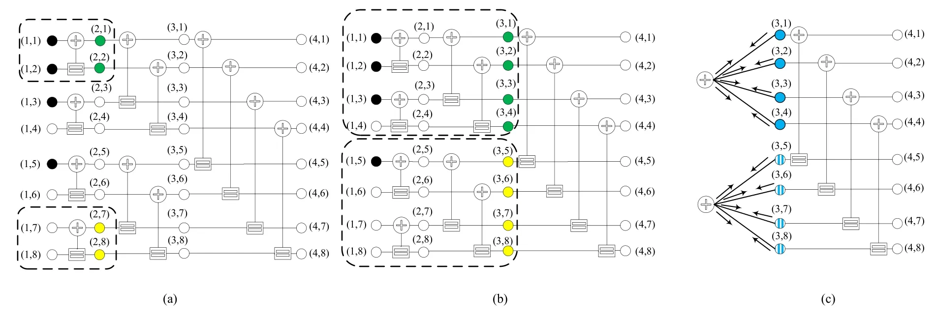
Figure 17.(a)Frozen nodes are in black color and information nodes are in white color(b)NREP codes are in green color and NSP C codes are in yellow color(c)Simplified NREP and NSP C nodes.
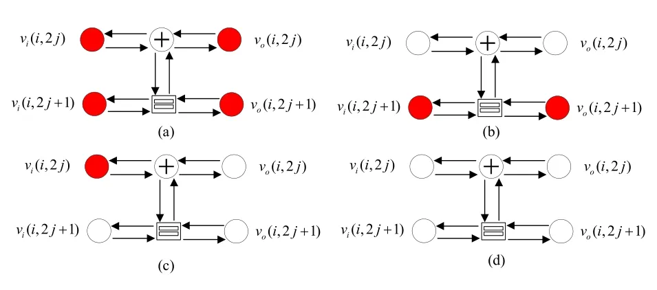
Figure 18.Four possible variable node permutations.
Another study for node classification and simplification is presented in[94]where four different types of PEs are defined as depicted in Figure 18 whereviandvorepresent input and output variable nodes,respectively.
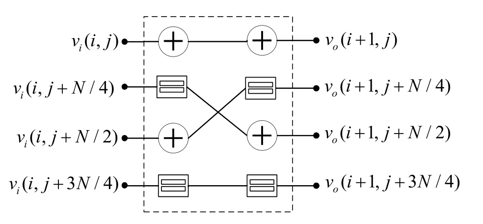
Figure 19.4 × 4 Basic processing element consisting of 2×2 PEs.
Equations for right and left propagation messages are simplified.It is shown in Table 2 of[94]that simplification of PEs provides approximately 75% complexity reduction in terms of multiplications and summations.In addition,the same performance of classical BP decoding algorithm is achieved.
4.2 Stage-Combined BP Decoding Algorithm
As depicted before,BP decoder consists of stages and each stage has a number of process elements.Parallel decoding property of the BP algorithm enables to process a stage at a time.It is clear that by combining adjacent stages,it may be possible to reduce the latency,complexity,and memory requirement for LLR values.Following this idea,a memory efficient BP decoding algorithm is proposed in[19]by merging four 2×2 PEs into a single 4×4 PE as shown in Figure 19.
Equations(7)-(10)are modified to handle needs of 4×4 PE and new equations are emerged[[19],Eq.(9)-(10)].The factor graph forN=16 that consisting of 4×4 PEs is depicted in Figure 20.As it is seen,two less stages are used to implement stage-combined structure of[19].Overall 2(log2N −1)clock cycles are sufficient for per-iteration.
The stage-combined decoding algorithm is implemented and synthesized using TSMC 45 nm Low Power CMOS technology,and it is seen that 18.4%area reduction is achieved for code length of 212compared to the implementation of classical BP decoding algorithm.However,it is important to state that stage-combining increases critical path,even doubles.Some other authors employed stage combining in[95]and they reported that approximately 0.2 dB gain is achieved at 10−4BER forP(1024,512)and storage requirement is halved.
4.3 Stochastic BP Decoding of Polar Codes
Stochastic computing is a good candidate[96]to decrease the complexity and consequently silicon area and power consumption of a decoder.In stochastic computing,a number is represented by bit streams in which the number of 1’s is decided considering the weight of the number,for instance,0.6 can be represented by streams 0110110101,1101001011 or 0111100101 and 0.5 can be represented by 0101100011 or 0111000011[96].A stochastic BP decoding algorithm for polar codes is presented in[97]where the original deterministic BP decoding algorithm is utilized for stochastic process.Different approaches to improve performance of the proposed method such as increasing bit streams’ length,rerandomization of bit streams are proposed.Moreover,BP decoder utilizing stochastic structure can be used to decrease the amount of computational complexity.
A novel bit-wise iterative stochastic decoding architecture for the BP algorithm is proposed to improve the throughput of the polar decoder in[98].Moreover,an optimized version of[98]is presented in[99]to further reduce the hardware cost and speed up convergence.Another novel stochastic decoding method is proposed in[100]to increase error correction performance of the BP decoder,and the proposed method over performs the BER of MS BP.In[100],stagewise re-randomization is used and,employed method shows the best BER results among the stochastic BP decoders.
4.4 Improved BP Decoding Algorithm with Modified Kernel Matrix
Factor graph of BP decoding algorithm used for a polar code consists of simple two-input two-output PEs.There areN/2 PEs at each stage of the decoder.BP based iterative decoding needs to save the previous node message,i.e.,likelihoods.This means that BP based iterative decoding operation needs memory units.To decrease the memory requirement of the iterative decoding operation,a 3×3 PE based decoder is designed[21,101].In Figure 21,2×2 PE based and 3×3 PE based decoder designs are illustrated.
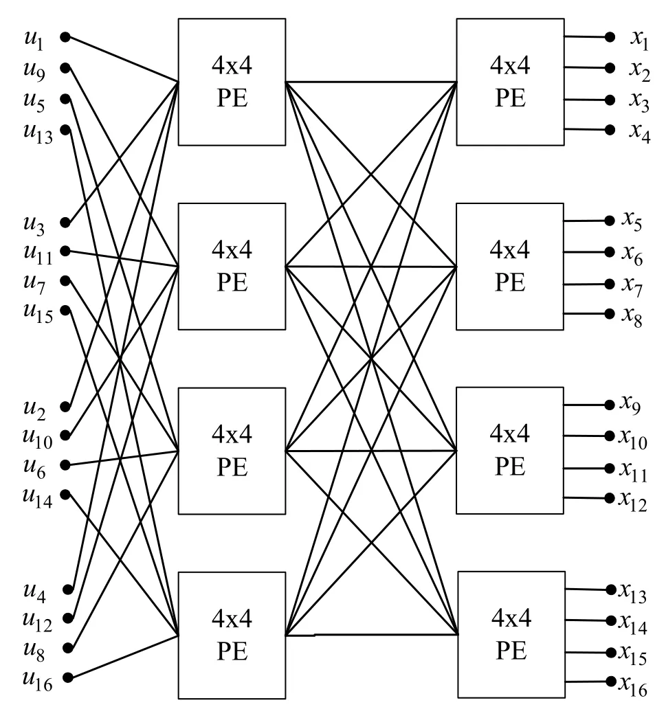
Figure 20.16×16 decoder consists of 4×4 PEs
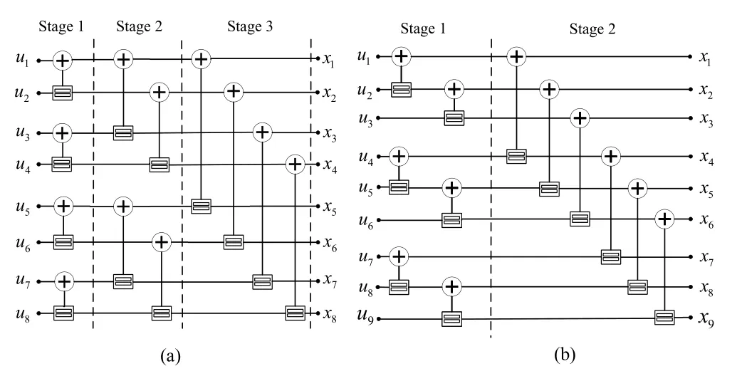
Figure 21.2×2 PE based encoder/decoder representation(b)3×3 PE based encoder/decoder representation.
3×3 PE based implementation reduce memory requirement and decoding delay by 37%.Besides BER/BLER performance are same with respect to original scheme while complexity is decreased.As noticed,simplification of BP polar decoder isn’t studied as much as BER performance enhancement studies.However,Node Classification and Unification Based BP polar decoding seems applicable and hardware friendly.
V.INCREASING DECODING SPEED
The BP decoding algorithm is suitable for parallel processing which enhances the throughput,on the other hand,its iterative processing nature has negative effects on the throughput.To decrease the number of iterations in iterative decoders,early stopping criteria have been studied extensively in well-known iterative decoders,such as LDPC and turbo decoders.As expected,well-known early detection and termination methods are applicable to BP based polar decoders,also.
Scheduling is also effective on increasing decoding speed.A scheduling method can converge decoder faster knowing that final estimation can be more accurate with converged likelihood values.
5.1 Early Detection and Termination Methods
Originally,an iterative BP based decoder works until a pre-defined number of iterations is reached.However,in most of the cases BP decoder converges before iterations are completed.Thus,early detection of convergence and termination of decoding operation becomes an issue.There are several number of techniques that is explained in this sub-section.Average number of iteration that is calculated after using an early detection and termination method is an important indicator about technique’s performance.However,it is not the only indicator to observe.Complexity and accuracy of the technique are also should be taken into consideration before applying it to a BP decoder.In this section,after explanation of each technique that is used for BP based polar decoders,we provide a performance table(Table 3)to guide the researchers and our point of view.
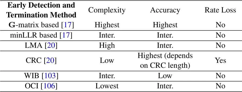
Table 3.Performance of early detection and termination methods.
The encoding operation for polar codes(like in all codes)is achieved using x=uG.At the decoder side,ifandare valid estimates,thenmust also be satisfied.By using this fact,an early detection and termination of BP polar decoding algorithm is proposed in[17],named as G-matrix based detection.In this study,at each iteration of BP decoding operation,is estimated at the leftmost nodes whileis estimated in the rightmost part of the decoder.Ifis satisfied for any iteration,then the decoding operation is assumed to be successful,and decoding operation is terminated.For high SNR region,i.e.,the region where SNR≥3dB,the method performs very well.The average number of iterations required can be reduced by 42.5%when SNR is 3.5 dB[17].
In log domain version of the BP decoding algorithm,the value of the estimated data bitis determined using the sign of the leftmost log-likelihood ratio values,This hard decision method utilizes only the sign part of theHowever,magnitude part also can be beneficial for detection.In[17],the authors considers checking allvalues and deciding on the ones exceeding a predefined threshold valueβ.If all values are larger thanβ,then decoding operation is assumed to be successful.It is also important to state that the choice of threshold value is very critical.[[17],Figures 7,8]states that differentβvalues have significant effects on both BLER performance and average number of iterations.An adaptive method is proposed to get an optimum threshold called as minLLRfor early detection.Channel estimation is employed for this purpose.It is shown in[[17],Figure 7]that an adaptive minLLRalgorithm withβ=2.5 when SNR≤3 dB and withβ=9.5,when SNR=3.5 dB gives better results,and the average number of iterations is reduced by 32.5%.
Hence,we can state that G-matrix based detection is superior to minLLR-based detection in terms of average number of iterations,however,minLLR-based algorithm is less complex.
Following the introduction of the early termination method that use the G matrix for the verification of equality,a number of studies employing G matrix for early termination are done in[18,22–24,42,102,103]for both comparing the newly discovered early detection methods and evaluating the performance improvements.
There are other early detection methods proposed in the literature apart from the G-matrix based approach for BP decoding of polar codes.In[102],the authors proposed that the hard decisions for the three consecutive iterations can be compared to each other and when no change is detected,then decoding operation can be terminated.Separately,a parity check matrix H is derived from the generator matrix G′where G′is ak×nmatrix consisting rows of matrix G.Rows of G′are selected from G considering the positions of the information bits.Consequently,early termination is applied according to.
Upon its introduction,minLLR-based detection method is used in[30]also to avoid redundant iterations when BP decoder has already converged.Moreover,LLR-Magnitude aided(LMA)early detection method is proposed[20]as a modification of minLLR-based detection.In this method,the rightmost nodes’LLR values of two adjacent iterations are compared to each other,and if they are same,then the decoding process terminates.For the maximum iteration numberMmax=30,it is seen that 69.4%reduction in iteration number is achieved atEb/N0=3.5 dB.Authors also searched the minimum number of iterations required for the convergence of BP algorithm,and employed CRC to reach it.
LMA and G-matrix based early termination methods can make wrong early termination decisions due to falsely converged LLRs.
The use of CRC is an effective way to avoid wrong early termination decisions with a margin of rate loss.A well-designed CRC can check perfectly whether decoder is successful or not.It is observed that CRC-32 is sufficient to make robust decision about the success of the decoding operation for block length of 512[20,104].The use of CRC-32 results in 82.8%reduction in iteration number atEb/N0=3.5 dB[20].Although performance is kept the same,the use of CRC decreases the decoding latency when compared to LMA.Besides,CRC aided structure can be used to estimate minimal number of iterations required[20,105].
A simplified early stopping criterion that is inspired from G-matrix based detection is proposed in[103].In this study,authors focus on a cluster of information bits that are polarized to the highest error probabilities,and this method is called as worst of information bits(WIB).Performance of WIB depends on two parameters.One of them isnWIB,number of WIB information bits,andM,the number of last iterations where sign of the WIB remains the same.It is shown in[103]that a choice of wherenWIB=N/8 can get values up to 2048 is sufficient to accomplish successful decoding.An equation is defined for the selection of WIB bits in[[103],Eq(5)].The complexity of WIB technique is less than that of the G-matrix based method,however,the performance of WIB technique is worse than the performance G-matrix based method.Moreover,a channel adaptive WIB method is provided in[103]to reach optimal results.
As implied in[102,103]an early termination method that checks whether hard decisions remain the same for m consecutive iterations or not is proposed[106].We named this method as observation consecutive iteration(OCI).From now on this method will be named as OCI.The only difference of this approach from WIB method is that the hard decision observation is done for all information bits not a part of them as stated in WIB termination[103].A more accurate but still simple version of[106]is demonstrated in[107].A threshold value(∈)that represents likelihood ratio information change value of information bit is defined as

Some other early termination approaches are proposed in[18,22]which are based on subfactor-graph freezing for BP polar decoder.This kind of approach leads to the faster convergence of the decoder.In other words,in BP decoding operation,nodes of some subfactor-graphs are checked for converge in every iteration,and if they have converged,then the converged nodes in these small structures are not updated anymore,and they are directly used in subsequent iterations.Simulation results show in[[22],Figure 8]that this kind of approach gives the same results as conventional BP decoder utilizing fixed number of iterations with a G-matrix based early stopping approach while average number of iterations are lowered.
A different approach of the WIB method presented in[103]is studied in[24].As stated before,WIB method checks a cluster of information bits that are polarized to the higher error probabilities.The idea of[24]is similar to the approach of WIB such that it checks whether a bunch of frozen bits that have the largest capacity values among all the frozen bits is converged or not.Main motivation of the method is the assumption of information bits are converged successfully if frozen bits are already converged.As a result,this new early termination method is based on the error rate of some frozen bits.The figure[[24],Figure 4]shows that the average iteration number is less than the average iteration number of WIB method while G-matrix based detection is still better than both of them.
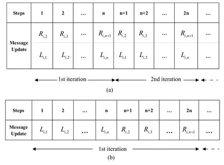
Figure 22.(a)Flooding scheduling(b)Round-trip scheduling.
Table 3 compares the performance of the early detection and termination methods in terms of complexity,accuracy of the method and states whether a rate loss is valid or not.
During our research on early detection and termination techniques,we understood that despite its complexity G-matrix based detection has best result.However,it has a matrix multiplication whose complexity grows with .As expected,matrix multiplication consumes too much resources on a logic device.
CRC,which is easier to implement when compared with G-matrix based estimation for early detection,is employed in[20,60,104,64,105].Two different approaches can be followed for CRC based for early detection.
Approach I:In the first approach,for a polar codeP(N,K)whereKis the length of the information bits,andN −Kis the number of frozen bits,the number of information bits is decreased fromKtoK −RwhereRis the number of CRC parity bits and the number of frozen bits is kept same.Thus,the code rate ranges fromK/NtoK −R/Ncausing rate penalty.
Approach II:In this approach,code rate is be kept the same i.e.,K/N.Number of frozen bits ranges fromN −KtoN −K −R.Both approaches are used in the literature,in[10,108,79]the first approach is employed,while in[105]the second approach is considered.In our study,we used both approaches to make a fair comparison with literature.Structure of CRC,i.e.,its polynomial representation,and its length are important parameters that affect the performance of the decoder.We choose CRC-6 forN=128,CRC-8 forN=512,CRC-16 forN=1024 andN=2048.
Polynomials are selected referring to papers and 5G standard documents[60,64,13]as:

Despite the code rate penalty,CRC usage is practical when compared with G-matrix based early detection method.Thus,one may prefer to use CRC method.It causes rate loss but we observed comparable outputs with G-matrix based detection method[84].Since,aim of[84]was to reach BER/BLER performance of CRC aided SCL decoder’s,we didn’t hesitate to use CRC aid in Na-BPL decoder as early detection and termination technique.However,it is not obligatory to use G-matrix based or CRC based detection in your study.If channel SNR is higher and high throughput performance of your decoder is your number one target,then WIB or observation of consecutive iteration results would be first choice for your decoder as depicted in[102,103,106,107].
Perfect knowledge based(PKB)early detection and termination method is used in[60,64]to show the BP decoder’s real potential to correct errors.In this method,BP polar decoder stops working when estimated data and user data u are the same.Similar comparison can be made between estimated codewordand x.Although,it is not possible to utilize PKB method in any decoder,it is used to show the lower bound of decoder error correction performance[60,64].
Until now,G-matrix based,CRC,minLLR,LMA,WIB and OCI early detection and termination methods have been studied.The accurate selection and application of the early detection and termination method is vital for BP-based decoders.Regardless of how the decoder is constructed,if the early detection and termination method is not working properly,the decoder will not show its actual performance.In this context,PKB method was used in some studies in order not to reflect the disadvantage of early detection method.Regardless,the conclusion from our literature review is that it will be useful to use some of the abovementioned methods jointly until a perfect method is found.
5.2 Scheduling
Scheduling is one of the main factors that affect performance of any iterative BP decoder.Scheduling is a kind of road map that is followed on factor graph of decoder during iterations of message propagation.Clever scheduling can lead improvement on decoder’s performance.Improvement can be achieved in terms of throughput,BER/BLER and complexity by applying different scheduling techniques.Moreover,scheduling of a BP decoder has a direct effect on convergence speed and hence latency.Scheduling is widely studied for LDPC decoders.The scheduling methods called as two way scheduling and flooding scheduling are introduced for the first time in[109]to be applied to LDPC decoder.There are five scheduling method defined to be utilized in BP polar decoders like flooding,round-trip,halfway,quarterway and SCAN scheduling.In this sub-section,scheduling methods are explained and demonstrated with figures to provide better understanding.
In flooding scheduling,the messages for each stage of the trellis are calculated from right to left and then from left to right.For a frame length ofN,there aren=log2Nstages consisting ofZshaped subgraphs.In each subgraph,the messages,i.e.,probabilities or likelihoods,are updated starting from lower horizontal edge and continued with diagonal edge,and finally upper horizontal edge is updated.A modified flooding mechanism is presented in[4,25]that utilizes a multilevel update process to lead faster convergence.Overall,average iteration number is reduced from 31.7%to 36.5%for the range of 2-3.5 dB when compared with flooding BP algorithm.
Unlike conventional BP decoder with parallel process ability,SCAN decoder[43]offers sequential decoding like SC but it uses soft messages to decode consecutive bits.In this manner,SCAN can be considered as a sequential BP decoder,and moreover it can be accepted as a different scheduling method[42].SCAN scheduling can improve the performance and reduce complexity[45,110,111].It is also important to state that original polar code construction method that is presented by Arıkan[2]uses SC decoder.As a soft version of SC,SCAN scheduling has advantage over flooding BP when Bhattacharya parameters are used to construct polar codes.However,with its serial structure SCAN scheduling causes much longer decoding latency.A method is proposed to reduce latency of the SCAN algorithm in[112]where average number of iterations is reduced significantly when compared to SCAN with a reasonable margin of BER loss.
RT scheduling is proposed[102],and it is further studied in[29]to lower iteration number and improve performance of BP decoder.In conventional scheduling of BP decoders,messages are computed at the same time for both left-to-right and right-to-left directions.The update ofLi,1andRi,2in step 1 and the update ofLi,2andRi,3in step 2 are shown in Figure 22a.On the other hand,in RT scheduling first the messagesLi,1toLi,nare calculated and then the messagesRi,2toRi,n+1are calculated.The RT scheduling is illustrated in Figure 22b.
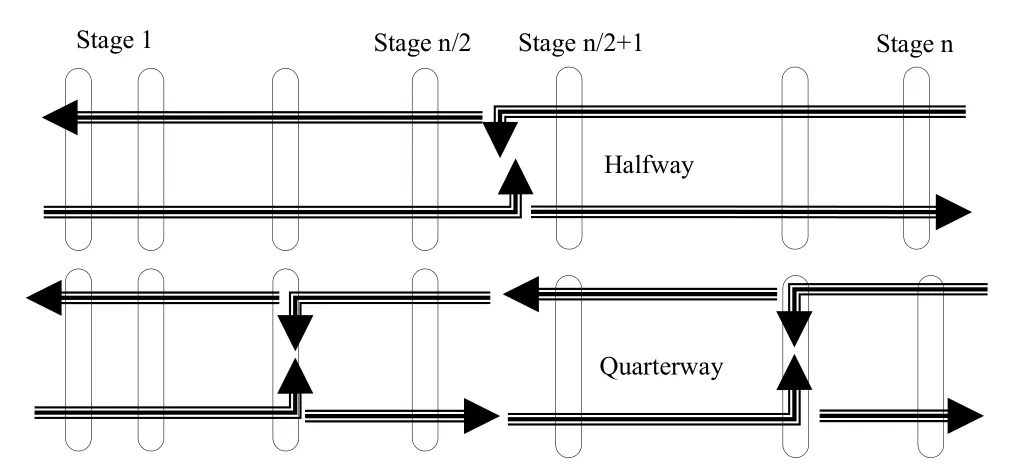
Figure 23.Halfway and quarterway scheduling.

Figure 24.4-level folded decoding scheme for N=16.

Figure 25.2-level folded decoding scheme for N=16.
In addition,in RT scheduling one iteration is performed in two steps.In the first step,the messagesLi,jare updated and in the second step,the messages flowing to the opposite direction,i.e.,Ri,j,are calculated.Employing RT scheduling the average number of iterations is decreased when compared to the conventional BP decoder,although the computation amount stays the same.The same performance of SMS BP is proven to be achieved[29].Moreover,RT scheduling is also studied in[24,110,84]shows that it is acceptable method to use.
Two other scheduling methods called halfway scheduling and quarter-way scheduling are introduced in[22].In halfway scheduling,information flow starts from leftmost and rightmost nodes towards to the middle of the BP factor graph at the same time.They meet at the middle and exchange messages.Newly formed information traverses back toward both leftmost and rightmost nodes at the same time.Figure 23 shows the information flow for both halfway and quarter-way scheduling methods.Quarter-way scheduling is nothing but divided version of halfway scheduling.Both methods can be considered as a modified version of RT scheduling.The aim of both methods is to decrease the latency of BP decoder enabling providing faster convergence with a handicap of increasing number of PEs,i.e.,complexity.
The small percentage of active hardware is another drawback of BP polar decoder.According to decoding procedure of conventional BP decoder,PEs are activated stage-by-stage from left to right in each iteration.Other PEs remain unused during information flow.To achieve 100% utilization,folding approach is introduced[113].4-level folded decoding scheme forN=16 is presented in Figure 24 wherestands for decoding stage and node.
Figure 24 shows that with one stage of PEs,decoding can be done in 12 clock cycles forN=16.Although 100% utilization is achieved,latency is increased.Folding scheduling can be changed by adding stages to lower latency.In this scope,Figure 25 demonstrates 2-level folded scheme ofN=16.
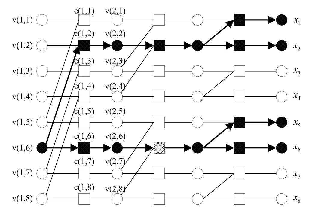
Figure 26.Stopping tree for variable node v(1,6).
In[[113],Table 1],it is shown that logic gate count and latency over conventional BP polar decoder can be lowered significantly by using folded decoding.
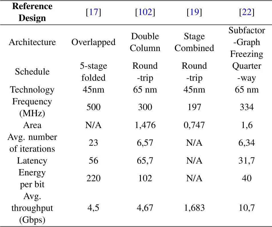
Table 4.ASIC implementation results of BP decoder for P(1024,512).
SCAN scheduling is defined in[43]as the soft version of Successive Cancelation algorithm that is invented by Arıkan[2].Originally,SC algorithm is a step by step algorithm means to decodemthbit all bits from 1 tomth −1 must be decoded.This type of scheduling allows to reach high BER performance but causes latency.Nlog2Ncylces are needed to decodeP(N,K)with SC or SCAN algorithm whileMlog2Ncycles are needed to decodeP(N,K)with BP based polar decoder whereMis smaller thanN,5 or 10 times.However,SCAN algorithm is still a strong candidate among soft decision based polar decoders to reach high BER/BLER performance.
When all the decoders in this sub-section are reviewed,it is seen that scheduling method has paramount effect on decoders’ BER/BLER and throughput performances.RT scheduling shows the best results while folded decoding scheme offers a tadeoff between throughput and complexity to developers.
VI.OTHER STUDY AREAS ON BP DECODING OF POLAR CODES
6.1 Polar Code Construction Methods
Split channel capacities presented in[2]are calculated using Bhattacharya parameters for SC decoding.For BP decoder,there is no proposal in literature for the split channel capacity calculations.The need for different polar code construction methods emerges from the fact that recursive Bhattacharya bound based estimation,Gaussian Approximation(GA)and Density Evolution(DE)are all suitable for SC decoding scheme.There is no exact frozen bit selection method proposed for binary discrete memoryless channels like binary erasure channel,binary symmetric channels and AWGN up to now.It is also important to state that,calculation based selection algorithms such as GA and DE show similar performance when compared to Arıkan’s recursive Bhattacharya estimation[114].To sum it up,alternative polar code construction methods powered by Monte Carlo(MC)simulations that gives better performance with BP based decoding are going to be mentioned throughout the rest of the section.
As mentioned before,a stopping set consists of a set of variable nodes such that every neighboring check node of the set is connected to at least two variable nodes.Stopping tree can be considered as a subset stopping set.A sample stopping tree for variable nodev(1,6)is shown in bold lines in Figure 26 wherecstands for check nodes whilevstands for variable nodes.
Leaf size is defined for stopping tree and it is an important parameter for decoding process.For instance,leaf size ofv(1,6)in Figure 25 is 4.Leaf set size oriented frozen selection is presented in[37].In this manner,information bits whose leaf set sizes smaller than 28(whenN=213)are set as frozen bits.Contrary,frozen bits with leaf size greater than 28 that are selected according to minimum Bhattacharya parameter,and they are converted to the information bits.With this polar code construction method,BP polar decoder outperforms BP polar decoder that is constructed with the Bhattacharya parameters.The method presented in[37]modifies the Bhattacharya parameter based construction method slightly.The modification idea originates from RM code which picks up information bits that has largest leaf sets.
In order to improve error correction capability of BP decoding schemes,simulation-based frozen bit selection method via MC trials is offered in[110,115–117].In these studies,better performance is achieved in BP decoding.In[116],MC trial based frozen bit selection is applied for data lengths of 128 and 256.Due to its complexity,no MC trial based construction is presented for higher block lengths.Alternatively,a schedule-adapted code construction method is presented in[110].RT scheduling on the factor graph of BP decoder has its own characteristics.Authors use two different approaches to construct polar code.In the first one MC trials are done using BP decoding with RT schedule.Since MC approach is time consuming,a second code construction algorithm is proposed.In the second approach,to overcome time consumption a jump-start MC construction is proposed.In this method,the initial index setting use RM(3,8)which provides an index set corresponding to the indices of the rows G of the highest Hamming weight.After initial index is set,then MC approach is used again.Better performance is achieved over GA based construction for the case of BP decoding with RT schedule atEb/N0=3 dB.As a result,authors elaborated on the existence of systematic ways to optimize polar codes for iterative decoding under a specific schedule[110].
MC based polar code construction requires significant amount of time for the block lengths larger than the one used in[110,116]where polar code construction is done for at most.To avoid time consumption,FPGA is used to accelerate MC trials[117].As a result,three month length time required to construct polar code for block length of 1024 through MC trials is reduced to 6.3 hours.In addition,authors offered three different methods for polar code construction,and these methods are summarized as follows:
•In One-Time Rank and Freeze Method
1.Set all bits as information bits,
2.Run MC on BP decoding simulations and measure the error rate of each bit,
3.Rank the bits based on error rate and freeze theN −Kleast reliable bits to obtain the bit selection for an(N,K)polar code.
•In Iterative Rank and Freeze Method
1.Set all bits as information bits.
2.Fori=1 toNitwhereNitis maximum iteration number of BP decoder
a.Calculate error rate for each non-frozen bit after MC simulations,
b.Sort non-frozen bits according to step 2.a calculations,and freeze least reliable one.
•In-order Bit Selection Algorithm
1.Fori=1 toN −1
a.Wheni=1,set all bits as information,
b.Wheni >1,freezeand set bitsas non-frozen,
c.Calculate error rate ofuiafter MC simulations.
2.Sort the bits according to error rate and freezeN −Kleast reliable bits.
Polar code with in-order bit selection algorithm is shown to outperform the polar code that is constructed with DE method when BP based decoding is applied.
Another MC based frozen bit selection method is presented in[21]which can be explained as follows:
1.Set code rate toR=1/N,i.e.one information bit for N different codes,
2.Perform simulations and observe error correction performance of different codes,
3.Record and sort error rates,
4.Choose the best one as information bit,
5.Increase the number of information bits and return to step 2,
6.Finish simulation when information bit is selected.
MC based frozen selection method presented in[21]is utilized forP(243,121).As mentioned before,MC based methods are applicable for short block lengths unless any latency reduction algorithm is not employed.Thus,more effective polar code construction method should be developed to reach optimum performance under BP based decoding.
LLR-based bit-swapping polar code construction method is proposed in[111].In this method,final LLR values of each split channel are observed after each iteration.From the channels chosen as frozen bits,twelve of the best 12 converged ones are reserved as data bits,and similarly from the channels used as data bits,twelve of the worst 12 converged ones are employed for frozen bits.This method is used for BP flooding decoder,BP SCAN decoder and also SCL decoder.It is seen that the code performance improves[111].Overall,MC based frozen bit selection is still attracting the researcher’s interest.
For the constructıon of the generator matrices of RM and polar codes the matrix F⊗nis employed.The difference between them is in the selection of channels that carry information bits.Polar code construction is based on Bhattacharya parameter calculation to minimize the error probability under SC decoding.It is not an optimum information bit selection method for BP decoding.Keeping this in mind,and knowing that RM construction is based on codes that have largest minimum Hamming distance,it is shown in[118]that for finite length codes distance parameter is more important than polarization effect.In this manner,a hybrid RM-polar code construction method is presented.This method can be implemented in three steps:
1.The index of the frozen bits are decided considering the Hamming weights of the rows of G matrix having a hamming weight less than a definite thresholdd,
2.N −Kinformation bits are chosen according to smallest Bhattacharya parameters from the remaining set,
3.Finally,remaining set of bits are chosen as frozen.
It is shown in[[62],Figure 4]that hybrid RM-polar code yields a slightly better performance than Bhattacharya based code under BPL and SCL decoding.Hybrid RM-polar codes increase the minimum distance;it gives better performance but not the best.Because,performance of linear code under iterative decoding is determined by the structure of stopping sets in the Tanner graph of the code[119].
Deep learning concept is also used for polar code construction i.e.,choosing frozen bits in any codeP(N,K)[75].Deep learning based estimation of frozen channels is a bit behind of Bhattacharya parameter based estimation forP(1024,512)in the AWGN channel environment.However,deep learning can be beneficial for polar code construction as it is a promising candidate for polar code decoding.
One of the best polar code construction method for a BP polar decoder is proposed in[120]where genetic algorithm is employed for the code design.The polar code designed using the genetic algorithm takes into account the structure of stopping sets in the Tanner graph of the code under iterative BP decoder.The BP polar decoder designed using the genetic algorithm achieves the result of SCL decoder(L=32)employingP(2048,1024)code over the AWGN channel.This result shows Genetic algorithm based code construction will be an optimum choice.
6.2 Errors in BP Polar Decoders
It is important to understand why decoding errors occur in a BP polar decoder to be able to avoid them.Structure of encoder,decoder,decoding algorithm/scheduling,and SNR are significant factors that affect BER performance of any forward error correction method.In the subject of BP based polar decoder,literature focuses on changing,upgrading the decoder structure,and the decoding schedule to avoid errors.Error sources,error types,and methods to eliminate different error types are covered in this section.
The stopping sets,which are defined in Tanner graph representation of LDPC codes,are also available to polar codes.A stopping set,S as defined is a subset of V,the set of variable nodes,such that all neighbors of S are connected to S at least twice[121].Figure 27 shows a sample stopping set in a polar code.Small stopping sets play an important role during decoding process and causes error floor[108].Stopping sets are also closely related with probability of error such that when nodes in a stopping set are erased or decoded wrongly,thenPeincreases.Especially,in Tanner graph based decoders,larger stopping sets yield lower BER values.
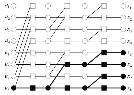
Figure 27.A sample stopping set on a polar code Tanner graph.
Smaller stopping sets cause error floor problem especially in LDPC and turbo decoders.When SNR increases,BER decreases in an exponential manner,however,if BER remains the same or decrease in a small rate then this means that the decoder has countered an error floor problem[36,59,122,123].Due to its larger stopping set size,polar codes show excellent error floor performance[122]such that error floor is not observed even at BER of 10−9.It is shown in[37,59]that frozen bit selection and stopping set size are closely related to each other.A modified frozen bit selection algorithm is developed by increasing the stopping distance of the polar code[37].
Another source of error floor is the girth of a graph[36,37].A girth is nothing but the length of the shortest cycle contained in a Tanner graph.Shorter cycles prevent BP algorithm to converge and this can be considered as a drawback,since fast convergence ability is directly proportional with the success of any iterative decoder.
Clipping on LLR values can also cause error floor[59].Clipping is needed to lower hardware complexity,especially when complex BP decoder is used.Lower clipping values tends to show error floor[[59],Figure 3].Four algorithms are offered to avoid error floor caused by clipping.These algorithms are summarized as:
a.Guessing algorithm is based on finding oscillating LLR values.After finding a sign of oscillation a threshold is assigned to help correct convergence.
b.Adding virtual noise to the input from the channel can help correct convergence.
c.Modified boxplus function inherits a scaling constant(αi.e.,0< α <1).Changing this constant can avoid saturation which causes error floor.
d.Multi-trellis BP decoder is proposed in[4]where it is stated that when conventional factor graph fails to converge,then a different oriented trellis can be used.Multi-trellis BP decoder is a promising candidate to improve BER performance significantly and is covered in a separate section of this tutorial.
Error floor caused by low clipping value can be avoided using the algorithms listed above[59].However,complexity reduction obtained by the employment of lower clipping value should be preserved when error floor avoiding methods are applied.
BP decoding scheme is a promising technique with its parallel structure providing higher throughput and a reduced latency.It is also important to understand how a BP decoder fails.For this purpose,an error classification is done in[123]for BP decoder to be able to handle them intuitively.Three error types are defined as:
a.Unconverged errors:When the decoder is unable to resolve the error and more iterations are of no use,then the error is called as unconverged error.There is no defnied error pattern in this type.
b.Converged errors:Converged errors occur when converging to wrong codeword or falling to local minima of BP decoding take place.If hard decisions are the same during the consecutive iterations,then it can be a converged error.This kind of errors cannot be recovered using more iterations[123].
c.Oscillation errors:BP decoding scheme suffers from propagation of incorrect messages due to its loopy structure.When decisions for these incorrect messages change periodically,it can be defnied as oscillation error.
Unconverged and oscillation errors can be detected by observing hard decisions in consecutive iterations,on the other hand,falsely converged errors can’t be detected.In different SNR levels,distribution of errors also differs.According to[123],unconverged errors dominates at low SNR whereas converged and oscillation errors become dominant as SNR increases.It is seen that when CRC is employed in BP decoding,most of the unconverged and a portion of oscillation errors are resolved successfully,however,converged errors still cannot be debated.
In the work[110],the authors use the error type definitions of[123],and they investigate error distributions under different scheduling(RT and SCAN),and polar code construction methods(like GA and MC based).Simulation results show similar outcomes are obtained under RT and SCAN scheduling.It is also seen that most decoding failures are caused by unconverged errors in low SNRs,and as the SNR increases converged errors dominates.However,unconverged errors are less effective when RT scheduling is employed.
Alternatively,three separate post-processing(PP)methods to avoid errors of all types are presented[83]where it is shown that with the use of PP methods,BP decoder achieves better BER performance when compared to SC decoder[[83],Figure 12].
6.3 Adaptive Strategies in Polar Decoders
The need for adaptive strategies in any coding scheme arises from the desire for better error correcting performance.Consequently,a wide variety of adaptive strategies are developed.In any decoder,SNR of any channel is a paramount factor on decoder BER/BLER performance and throughput.SNR oriented adaptive strategies in BP based polar decoding are also studied for further performance gain.
An adaptive early detection and termination method is proposed for minimum magnitude LLR based detection approach of[17].Different threshold values are applied for possible SNR values to find out optimum convergence condition.Another early detection method that is adapted to SNR change is WIB[103].With adaptive WIB,average iteration is decreased over fixed WIB.
An adaptive parity check matrix construction based channel estimation method is presented in[30]motivated from the fact that received LLR values are closely related to channel SNR.Overall,adaptive parity check matrix based decoding has shown better BER performance over SCL decoder.
Adaptive quantization is also studied in[106]to lower complexity of BP polar decoder.Simulation results show that fine precision is needed at low SNR values whereas coarse precision is sufficient at high channel SNR values.
Meanwhile,adaptive polar code construction is developed for the method of “In-order Bit Selection Method”[117]that is presented in section 6.1.Frozen bits are selected for five SNR values ranging from 1 dB to 5 dB on AWGN channel.Simulation results show that at high SNR values,polar codes constructed with 4 dB and 5 dB give better BLER performance whereas no significant difference is observed in BER performance.To sum up,channel SNR adapted strategies that improves performance and lowers complexity of the BP based polar decoder are classified.Moreover,applied scheduling technique can also be a subject of adaptive studies.
A channel SNR estimation method is needed for the use of adaptive methods.A novel algorithm that is based on Hamming distance betweenG andis proposed in[17]where a new parameterλis introduced and the new parameterλequals to 0 when=G.As expected,λtakes large values at low SNR values,and it takes small values at high SNR region.As a result,the relationship betweenλand channel SNR is utilized for the presented adaptive method.
6.4 Hardware Implementation
Hardware implementation of BP based polar decoders is an important issue to prove its superiority over SC and SCL structures.Implementations are accomplished on three different hardware platforms:FPGA,GPU and Application Specific Integrated Circuit(ASIC).These platforms are capable of making parallel processing that is needed for BP based algorithms.
First hardware implementation of BP polar decoder is offered in[124]by using an FPGA device.Typically,an FPGA consists of matrix of configurable logic blocks connected through programmable interconnects,and they are mostly used for handling parallel operations.It is one of the best candidates among hardware platforms to perform BP decoding.The performance of BP decoder is compared to the convolutional turbo code(CTC)which is used in the IEEE 802.16 standard on an FPGA.It is seen that,BP decoder is better in terms of complexity and throughput,but it not better than CTC in BER performance.Additionally,the BP decoder can achieve 27.83 Mbps for polar codeP(1024,512)[124].
The fully parallel BP decoder involving feedforward pipelined BP decoder and feed-back pipelined BP decoder is presented[125]where pipelined architectures are implemented in FPGAs,and an achievement for a desired trade-off between performance,throughput,latency,area and utilization is obtained.
A modified BP decoder implementation is done on an FPGA platform in[23]where an early stopping criteria using high-speed parallel-prefix Ling adder is used,and a throughput of 9.45 Gbps is achieved with simplified processing element(PE).
Another hardware platform for the implementation of BP decoder is the GPUs which are designed to perform rapid mathematical calculations,especially for the image rendering.It has parallel computation capability which is vital for BP decoder.Basically,a GPU consists of a set of CPUs that can do calculations in parallel.First GPU based example of BP polar decoder is introduced in[126]forP(1024,512),and it is reported that a throughput of 3.55 Mbps is achieved.A higher throughput of 34 Mbps is observed in[53]where a hybrid structure BP-SCL is implemented on a GPU by using NVIDIA CUDA C programming.In[127],it is shown that 1 Gbps throughput for the codes with lengthN ≤1024 at 5 dB over AWGN channels by using a GPU device can be achieved.In[59]the authors investigate the clipping effects on error floors under BP decoding of polar codes on a GPU platform.A SIC based implementations achieves best throughput performance.ASICs are customized to handle the needs of parallel structure of BP decoder and different scheduling techniques are presented in[17,19,22,102,113,92,93].Table 4 gives ASIC implementation results in terms of frequency,area,average number of iterations,latency,energy per-bit,and average throughput.Further comparisons with other decoding schemes(SC,SCL),and with other hardware platforms are also studied[128].As an alternative to CMOS devices,finFettechnology is emerged.finFetbased designs can lead power consumption and decoding delay reduction.Thus,finFetand near threshold computing technologies are utilized to achieve high-speed low-power BP polar decoder[129].WithfinFettechnology,critical path delay can be lowered up to 110 ps whereas critical path delay of 45 nm TMSC design is 1050 ps.
Polar encoding can be considered as a transformation which is illustrated using cascaded butterfly structure.Fast Fourier Transform(FFT)is also demonstrated via cascaded butterfly structure.A study to enhance the throughput and hardware efficiency of BP is performed using FFT processors in[130]where FFT processors are utilized for polar the decoding of polar codes using BP algorithm,and hardware design metrics like area efficiency,power consumption,and throughput are compared.
VII.OPEN RESEARCH CHALLENGES
Presented studies showed that BP polar decoder is a promising candidate for CRC based SCL decoder in terms of performance,throughput and complexity.Multi-trellis based structures are proved to be efficient to improve BER performance.Thus,it is showed that parallel BP decoders(BPL)with different permuted trellis structures achieves better performance over SC and SCL decoders[62].Alternative to multitrellis based BP list decoder,Na-BPL decoder is presented with better BER/BLER performance by closing CRC-SCL decoders’performance.As one of the best performed BP based polar decoder it has complexity problem.Complexity reduction of Na-BPL decoder is still an open research challenge.
Early detection and termination methods presented in section 5.1 are vital to decrease the decoder’s overall latency.However,complexity of the methods is a controversial topic.Adaptive strategies are also an interesting topic to get comparative results,especially with respect to channel SNR.It is also important to state that in order to apply adaptive strategies,channel SNR estimation need to be accomplished successfully.Although,adaptive strategies are studied well,channel SNR estimation method injection to BP decoder is a wide open for future studies.
Deep learning based studies are popular nowadays in many fields.Since they offer performance boost in terms of BER performance,decoding latency reduction,complexity and etc.However,training time and complexity of the operation should be studied more to achieve applicable strategies.
Genetic Algorithm based polar code construction method has best BER performance recordings for BP based polar decoder.A more detailed genetic algorithm study that is especially focuses on mutation and cross-over stages of operation is waiting to be accomplished.
VIII.CONCLUSION
Coding schemes are still one of the best choices to overcome channel noise and maintain reliable communication for the next generation 5G wireless systems.Polar codes are chosen for control channels of eMBB communication services,and they are candidate for data and control channels of mMTC and URLLC.Moreover,as the latest presented coding scheme,2007,polar coding is a promising technique for upcoming communication standards.Meanwhile,BP based polar codes with their parallel structure are suitable for soft information exchange between other decoding schemes.In this work,different types of BP polar decoders are presented.Focus of presented designs differ among throughput,latency,complexity and BER or BLER performance issues.Parallel decoding of polar codes is one of the most important property of BP based decoder.BP decoder has two main disadvantages which are lower BER/BLER performance over CRC aided SCL and higher complexity over SC.For this reason,to further enhance the performance of BP decoder,SMS BP decoder,paritycheck matrix based decoder,modified BP polar decoder with check nodes,concatenated polar decoder,hybrid decoders and multi-trellis BP decoders are presented in the literature to improve BER/BLER performance of the BP based decoders,and improved BP decoder with modified kernel matrix,node classification and unification based decoder,stage combined decoders and stochastic BP polar decoder are presented to decrease the complexity of the BP scheme with no performance loss.A variety of early detection and termination methods to decrease the iteration number of BP decoders are also studied in the literature.Latency decrement and throughput increment are possible if early termination is performed when nodes are converged.Another topic of interest is the selection of frozen bits in polar code design process.As mentioned before,Bhattacharya parameter based selection is designed for SC decoding scheme,and it is shown that it is not the optimal method when other decoding schemes,and scheduling algorithms are used.A number of polar code construction methods are presented to handle the need for an optimal model for BP based polar decoder.To sum up,if performance improvement of BP over CRC-SCL is achieved with acceptable complexity,then polar codes will be subject to more 5G framework standards that needs low latency,high reliability and low complexity.We hope this tutorial will give researchers about working on polar codes.
- China Communications的其它文章
- Two-Timescale Online Learning of Joint User Association and Resource Scheduling in Dynamic Mobile EdgeComputing
- SHFuzz:A Hybrid Fuzzing Method Assisted by Static Analysis for Binary Programs
- SecIngress:An API Gateway Framework to Secure Cloud Applications Based on N-Variant System
- Generative Trapdoors for Public Key Cryptography Based on Automatic Entropy Optimization
- A Safe and Reliable Heterogeneous Controller Deployment Approach in SDN
- Distributed Asynchronous Learning for Multipath Data Transmission Based on P-DDQN

