Analytical algorithm for longitudinal deformation profile of a deep tunnel
Qin Fng, Gn Wng, Fuci Yu, Jinming Du
a Key Laboratory of Urban Underground Engineering of Ministry of Education, Beijing Jiaotong University, Beijing,100044, China
b Beijing Academy of Safety Science and Technology, Beijing,101101, China
Keywords:Deep tunnel Elastic solution Longitudinal deformation profile (LDP)Tunnel face Displacement
ABSTRACT To investigate the longitudinal deformation profile (LDP) of a deep tunnel in non-hydrostatic condition,an analytical model is proposed in our study.In this model,the problem is considered as a superposition of two partial models, and the displacement field of the second partial model is the same as that of the concerned problem. Therefore,the problem can be solved by a model with simple boundary conditions.We obtain the solutions for the stress and displacement fields of an infinite body caused by arbitrary surface tractions on the boundary of the coming tunnel (zone inside the tunnel before excavation) by integrating the extended Kelvin solution over the boundary.The obtained stress solution is used to solve the specific surface tractions, which can satisfy the boundary conditions of the second partial model, on the boundary of the coming tunnel in an infinite body.Then,the specific surface tractions are substituted into the obtained displacement solution to solve the displacement on the wall and face of the tunnel.Therefore,the LDP can also be calculated.The proposed solution is verified by both numerical simulation and the LDP functions recommended by other researchers.The major advantage of our analytical model is that it can consider the effects of the axial and horizontal lateral pressure coefficients. It is revealed that the horizontal lateral pressure coefficient majorly affects the LDP behind the tunnel face, while the axial lateral pressure coefficient dominates the LDP ahead of the tunnel face. Furthermore, the deformation characteristics of the LDPs ahead of the face and the unexcavated core are investigated.The axial displacements of the excavation face can be used to predict the crown displacements ahead of the face.© 2021 Institute of Rock and Soil Mechanics, Chinese Academy of Sciences. Production and hosting by Elsevier B.V. This is an open access article under the CC BY-NC-ND license (http://creativecommons.org/licenses/by-nc-nd/4.0/).
1. Introduction
The convergence-confinement method provides a practical and straightforward way to solve the ground-support interaction during tunnel excavation(Oreste,2003).The longitudinal deformation profile (LDP), a key component of the convergence-confinement method, relates the tunnel wall deformations to the location along tunnel axis, behind and ahead of the tunnel face (Fig. 1).When the excavation face reaches a specific point,a portion of the maximum tunnel wall deformation, called pre-deformation, has already taken place.The tunnel wall will continue to move inwards along the tunnel face to advance further beyond the concerned point. The LDP can be used to determine the appropriate location for installing tunnel support (Vlachopoulos and Diederichs, 2009).

Fig. 2. Sketchs of partial models: (a) The first and (b) second partial models.

Fig. 3. Components of stress vectors on the tunnel wall and face.
A series of functions,obtained by fitting three-dimensional(3D)numerical simulation results under hydrostatic stress conditions,has been proposed to describe the LDP. Some researchers (e.g.Corbetta et al., 1991; Panet, 1995) obtained the functions of LDP behind the circular tunnel face in elastic condition.Unlu and Gercek(2003) noted that the LDPs in front of and behind the face did not follow a single continuous functional relationship, and they proposed two functions to describe the LDPs in elastic condition in front of and behind the face, respectively. Vlachopoulos and Diederichs (2009) proposed functions for the LDP considering the influence of plastic radius associated with tunnel excavation.Basarir et al.(2010)incorporated the rock mass rating(RMR)value into the LDP functions after multiple regression analysis of data obtained from arranged elastoplastic numerical models. Sakcali and Yavuz (2019) introduced the rock material properties (σci, mi)into the LDP functions based on the study of Basarir et al. (2010).The LDP can also be obtained by fitting field monitoring data.Carranza-Torres and Fairhurst (2000) presented an empirical function suggested by Hoek for the estimation of the LDP according to the monitoring data of a tunnel in the Mingtam Power Cavern project in Taiwan,China(Chern et al.,1998).In addition,the LDP can be obtained by numerical back analysis (Luo et al., 2018; Zheng et al., 2021) and laboratory tests (Song and Marshall, 2020; Li et al., 2021).
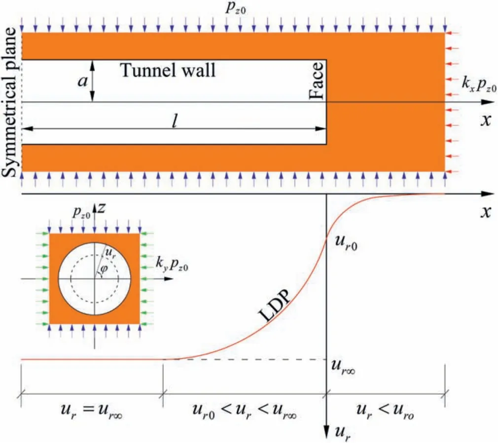
Fig.1. LDP and definition of geometrical variables.
Currently, there is no analytical solution available for this complex 3D problem, although the analytical solution can provide insights into the general nature of the problem (i.e. the influences of the variables involved). Moreover, most of the LDP functions were obtained under hydrostatic stress conditions, most of which are unsuitable to describe the actual stress conditions of a tunnel project. In this research, an analytical elastic solution is presented for predicting the LDP of a circular tunnel under non-hydrostatic condition. Our proposed model is verified by both numerical simulation results and other LDP functions.The influences of axial and horizontal lateral pressure coefficients on the LDP are investigated. The relationships between the axial displacement of the unexcavated core and the LDP ahead of the face are also studied.
2. Problem description
In this study, we propose an analytical elastic solution for the LDP of a deep, circular tunnel in non-hydrostatic stress condition.The surrounding ground is considered as a homogeneous, linear elastic and isotropic material. The tunnel radius is a. The distance from the tunnel face to an arbitrary point on the tunnel wall is x.The initial stress conditions,before tunnel excavation,are described using px0, py0, and pz0, which are applied along the vertical direction, tunnel axis, and horizontally perpendicular to tunnel axis,respectively (Fig. 1). The magnitudes of the initial stresses satisfy the following equation:

where kxis the axial lateral pressure coefficient, which can be represented as the ratio of axial to vertical stress; and kyis the horizontal lateral pressure coefficient defined as the ratio of horizontal to vertical stress. The sign conventions for the initial stress and the components of the stress vector and stress tensor are defined as positive for tension and negative for compression.
3. Solution method
3.1. Calculation model
After tunnel excavation, we immediately apply a series of balanced surface tractions on the wall and face of the tunnel. The balanced surface tractions do not change the stress and displacement fields. According to the superposition principle of elasticity,the problem can be solved by two partial models. The first partial model describes a deep tunnel with initial stresses pz0and px0.The surface tractions-Pr1and-Px2are applied on the wall and face of the tunnel(Fig.2a),respectively.Therefore,the first partial model is in a balanced state, and zero displacement will be produced. The second partial model describes a deep tunnel applied with Pr1and Px2on the wall and face of the tunnel (Fig. 2b), respectively. The sum of the displacement fields of the two partial models is equal to the displacement field of the proposed problem. As the displacement of the first partial model is zero,we can calculate the required displacement field by solving the displacement field of the second partial model alone.
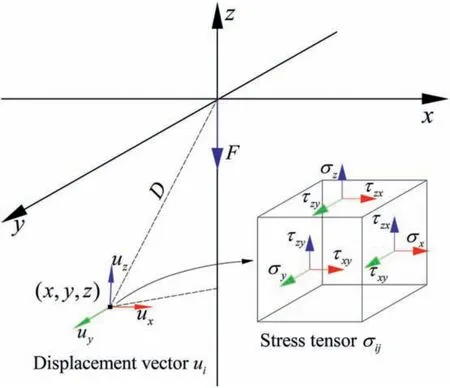
Fig. 4. Stress tensor and displacement vector of a point in Kelvin solution.

Fig. 5. Surface tractions: (a) Normal surface tractions Fr1 and Fx2; and (b) Tangential surface tractions Fx1 and Fr2.
The stress boundary conditions of tunnel wall and face in the second partial model can be respectively calculated by

where px1, py1, and pz1are the components of the stress vector acting on the plane with normal(Fig. 3, where φ denotes the angle with respect to y-axis).The first subscript in Eqs.(2)and(3),such as x,y,and z,indicates the direction of the stress components,and the second subscript indicates the plane where the stress vector is applied(i.e.1 representson the wall,and 2 representson the face). For instance, px1is the normal stress component acting on the plane of the wall, and py1and pz1are the tangential stress components on the plane of the wall. Similarly, the components of the stress vector acting on the face are denoted by px2,py2,and pz2. These rules are also suitable for other parameters in the subsequent text. There are two major advantages of our analytical model. On one hand, the boundary conditions are sufficiently simplified. On the other hand, the initial stresses need not to be considered.
3.2. Formulation derivation
The Kelvin solution (Timoshenko and Goodier, 1951) was proposed for calculating the equilibrium state of a linear elastic and isotropic material body occupying the whole space and being subjected to a concentrated force (Fig. 4). The displacement and stress states of a point in the infinite body can be obtained as follows:

Fig. 6. The small surface element of integral and the considered point.
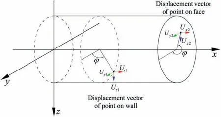
Fig. 7. The displacement vectors of the concerned point on the wall and the face.

where ν is the Poisson’s ratio, G is the shear modulus, F is the concentrated force, and D is the distance between the concerned point and the origin of the Cartesian coordinate system.To simplify the derivation process, we use stress tensor σijαand displacement vector uiαto express the displacement and stress states of a point as follows:

where the subscript α denotes the direction of the concentrated force applied at the origin. According to the classical Kelvin solution,the concentrated force is applied along the z-axis.To cater for the proposed problem, we extend the Kelvin solution to solve the problems that the forces are applied along the x- and y-axis,respectively.
As shown in Fig.5,surface tractions are applied on the wall and face of the coming tunnel (zone inside the tunnel before excavation).Normal surface tractions,Fr1and Fx2,are normal to the plane(Fig.5a),and tangential surface tractions,Fx1and Fr2,are parallel to the plane(Fig.5b).In the Cartesian coordinates,Fy1and Fz1are the projections of Fr1in the plane of yoz. Similarly, Fy2and Fz2are the projections of Fr2. These surface tractions can be noted by Fαβ,where the first subscript α indicates the direction and the second subscript β specifies the surface where it acts.
The surface tractions can be considered to be composed of a number of concentrated forces(i.e.aFα1dxdθ or rFα2drdθ)on a small surface element of the boundary of the coming tunnel(Fig.6).The stress and displacement associated with the forces on such elements can be solved by the extended Kelvin solution. Finally, the stress and displacement fields due to the surface tractions in an infinite body can be obtained by functional matrix integral.
In the process of integral,the polar coordinate system is used to describe the location of the small surface element on the face(l,r,θ)and the wall (x, a, θ) of the tunnel. The relationship between the Cartesian and the polar coordinates is denoted as

The polar coordinate of the concerned point is(X,R,φ),as shown in Fig. 6. When the integral is taken over the wall, to satisfy the requirements of the Kelvin solution,the relative coordinates of the concerned point with respect to the concentrated force is considered in the calculation. The relative coordinates of the point with respect to the wall and the face are(X-x,R-a,φ-θ)and(X±l,Rr,φ-θ),respectively.The stress tensor of a point due to the surface tractions applied on the wall and the face can be obtained:

Fig. 8. Scenarios for proving convergence of iteration: (a) Scenario I; (b) Scenario II; (c) Scenario III; and (d) Scenario IV.

For simplicity, Eqs. (9) and (10) are summarized as

where β represents the surface on which the tractions are applied.Different surfaces mean different integral regions.When β=1,Eq.(11)represents the integral over the tunnel wall(i.e.Eq.(9)).When β = 2, Eq. (11) represents the integral over the face (i.e. Eq. (10)).
The integral of the displacement vector follows the same way as that of the stress tensor.The displacement vector of the concerned point can be expressed as

where η represents the direction of the component of the displacement vector.In elastic mechanics,the relationship between the stress tensor of a point and the stress vector on the plane with normalis given as follows:

where the left hand side is the stress vector shown in Fig.3.The first term in the righthand side is the stress tensor,and the second term is a vector representing the cosine of the angles betweenand the three Cartesian coordinate axes.The second term for different γ values are written as follows:

Substituting Eq.(11)into Eq.(13),the stress vector acting on the wall and the face are written as follows:

where pxγαβ,pyγαβand pzγαβrepresent the components of the stress vector in the x-, y- and z-axis, respectively. These components can be summarized as pηγαβ. In the same way, the components of the displacement vector can be denoted as Uηαβ.
To facilitate the subsequent analysis, a new notation system is created for the components of stress vector and displacement vector.

where pηγrepresents the components of the stress vector caused by the surface traction Fαβ. Similarly, the components of the displacement vector are denoted by Uη (Fig. 7).
3.3. Inner boundary conditions
The solutions for the stress and displacement fields, caused by surface tractions on the boundary of the coming tunnel, are obtained in Section 3.2.To simulate the actual excavation process,the obtained stress solution is used to solve the specific surface tractions to satisfy the inner boundary conditions described in Eqs.(2)and(3).The specific surface tractions that satisfy the required inner boundary conditions are calculated as follows:

where the left hand side shows the components of the stress vectors caused by the specific surface tractions Fαβ,and the righthand side shows the values obtained by Eqs. (2) and (3). The iterative method is adopted to solve Eq. (18), which can be given by
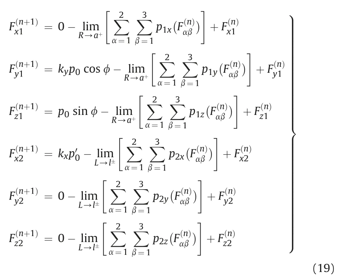
The convergence of Eq. (19) before iteration should be proved.Although it is difficult to prove it directly by mathematical methods, we can prove it by considering the problem characteristics. To do so, we establish four scenarios as shown in Fig. 8. Scenario I describes a tunnel with Pr1and Px2on the tunnel wall and face, respectively (Fig. 8a), and associated displacements are produced. We assume that the same displacements are produced on the boundary of the core due to surface tractions F′r1andon the curved surface and plane surface of the core,as shown in Scenario II (Fig. 8b). Scenarios I and II are combined together in Scenario III (Fig. 8c), in which Fr1= Pr1+F’r1and Fx2= Px2+ F’x2are applied on the interface between the core and the surrounding ground. We hope that the displacements of Scenario III were the same as those of Scenarios I and II. However, there are some differences in the produced displacements among the three scenarios due to the compatibility of deformation in Scenario III,resulting in shear stresses on the interface in Scenario III. Therefore, shear stresses Fx1and Fr2should be applied on the wall and face of the coming tunnel to eliminate the shear stresses on the inner boundary of the infinite body(Fig.8d).Consequently,the existence of Fr1, Fx2,Fx1,and Fr2can be proved,and the solution of Eq. (19) is convergent.
To evaluate the convergence of iteration, we use a function to estimate the errors and determine the numbers of iteration:

where err is the relative error,F(0)is the initial surface tractions,F(n)represents the result of iteration, and ‖·‖∞represents the infinity norm of the vector.
After solving the specific surface tractions satisfying the stress boundary condition, the displacement of any point can be calculated by substituting the specific surface tractions into Eq.(17).As a result, the LDP can also be obtained.
3.4. Calculation procedure
The calculation procedures are described as follows:
(1) Step 1: The concerned problem can be considered as a superposition of two partial models,and the displacement field of the second partial model is the same as that of the problem. We take the second partial model as the calculation model, and its stress boundary conditions can be described by Eqs. (2) and (3).
(2) Step 2:The stress and displacement fields of an infinite body caused by arbitrary surface tractions on the boundary of the coming tunnel can be obtained by integrating the extended Kelvin solution over the boundary (Eqs. (12) and (15)).
(3) Step 3: The obtained stress solutions (Eq. (15)) are used to solve the specific surface tractions, which satisfy the boundary conditions of the second partial model, on the boundary of the coming tunnel in an infinite body(Eqs.(18)and (19)).
(4) Step 4: The specific surface tractions obtained in Step 3 are substituted into the displacement solutions (Eq. (12)) to solve the displacement at tunnel crown.
4. Verification of proposed model
In this section, five different calculation conditions are established to validate the consistency and accuracy of our proposed analytical model. In the five calculation conditions, the values of k are taken to be 0.2,0.4,0.6,0.8,and 1,respectively,and both kxand kyare equal to k.The results of our analytical model are compared with numerical simulation results and LDP functions recommended by other researchers (Corbetta et al., 1991; Panet, 1995;Carranza-Torres and Fairhurst, 2000; Unlu and Gercek, 2003;Vlachopoulos and Diederichs, 2009). The results of our analytical model and the functions of others are calculated by MATLAB. A commercial finite difference code FLAC3D(Itasca,2012)is compiled to obtain the numerical simulation results.
4.1. Iteration threshold of proposed model
The precision of proposed analytical solution is influenced by integration,limit function,and total number of iterations.The first two factors can be controlled by taking proper MATLAB functions.For example, the numerical integration can be carried out by 8-order Newton-Cotes formulae,and the MATLAB built-in function is adopted to calculate the limit.The accuracy of our analytical model is related to the number of iterations.Therefore,we use the relative error to evaluate the convergence during iteration. When the relative error is smaller than 1×10⁻⁶,the accuracy of the proposed analytical solution is adequate,and the magnitude of displacement is acceptable. The relationships between the relative error and the total number of iterations of the five different conditions are displayed in Fig. 9.

Fig. 9. Relative error with respect to the total number of iterations.
In general,the computation with our analytical model takes 1 h with CPU i7-8700. In contrast, the computation with numerical model takes 2.5 h.
4.2. Numerical simulation model
In numerical simulation,only one-quarter of the tunnel and the surrounding ground are considered due to symmetry in geometry and boundary conditions. The dimensions and the boundary conditions of the model are shown in Fig. 10. Both the vertical and horizontal boundaries are located 10a(a is the tunnel radius)away from the tunnel axis,and the boundary perpendicular to the tunnel axis is located l away from the face. The normal velocities of the gridpoints along the bottom,front,and horizontal boundary planes are fixed to be zero,respectively(Fig.10).Before tunnel excavation,the initial equilibrium is reached under gravitational loading applied on the outer boundaries. The initial displacements of the gridpoints throughout the solid are initialized to zero. The characteristics of the tunnel are as follows: tunnel radius a = 6 m;Poisson’s ratio ν = 0.3, shear modulus G = 1.5 GPa, and vertical stress pz0= 4 MPa.

Fig.10. Geometry and boundary conditions of the numerical model: (a) Longitudinal and (b) transverse profiles.
4.3. Comparisons of calculation results under hydrostatic condition
Under hydrostatic condition,both the LDP functions of previous studies and the numerical simulation results are used to validate the consistency and accuracy of our proposed analytical model.The solutions of the LDP in previous studies are listed in Table 1.

Table 1 Solutions of LDP.
The LDP function is normalized with respect to its maximum deformation (ur∞) to eliminate the influences of in situ stresses(pz0), deformation properties of the solid (E and ν), and tunnel radius a on the magnitude of elastic displacement associated with tunneling. Moreover, the maximum deformation ur∞of the concerned point can be calculated by two-dimensional (2D) planestrain analysis proposed by Brady and Brown(1993):

where θ is the angle of the point on the wall in polar coordinates.
Under hydrostatic condition, the vertical stress is equal to horizontal stress and axial stress(i.e.ky=1 and kz=1).The maximum radial displacement can be simplified as

The results of our analytical model, numerical simulation, and functions recommended by previous studies are shown in Fig.11.The results of our analytical model agree well with the others. As the functions recommended by Carranza-Torres and Fairhurst(2000) consider the Hoek-Brown failure criteria, their results differ significantly from the other curves.

Fig.11. Normalized LDPs of our analytical model, numerical simulation,and functions recommended in the literature.
4.4. Comparisons of calculation results under non-hydrostatic condition
Under non-hydrostatic conditions, the results of our analytical model can be verified by numerical simulation results.The LDPs of two points at crown and sidewall under different lateral pressure coefficients, obtained by both our analytical model and numerical simulation, are shown in Fig.12.

Fig.12. LDPs at (a) crown and (b) sidewall for different lateral pressure coefficients.
The LDPs at crown obtained by numerical simulation and proposed analytical model have slight differences.The maximum error between the results of our analytical model and numerical simulation under different conditions is reported when the excavation face moves far away from the concerned point,and the value is only 2.24% under the same condition. At the sidewall, the results obtained by our analytical model also agree well with the numerical simulation results, although there are some differences near the excavation face under some conditions.
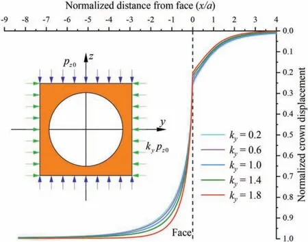
Fig.13. Normalized LDPs for different horizontal lateral pressure coefficients.
5. Result analyses and discussion
In this section, we analyze the effects of the lateral pressure coefficient on the LDP of the crown. To facilitate the comparison,the LDP is normalized with the maximum deformation ur∞as

5.1. LDPs under different horizontal lateral pressure coefficients
To investigate the influences of the horizontal lateral pressure coefficient on the LDP, several calculation conditions are considered,i.e.the horizontal lateral pressure coefficients(ky)are varied,while the axial lateral pressure coefficients (kx) are kept at 1(Fig.13).
The influence of kyon the LDP behind the excavation face is more evident than that ahead of the face.In the region behind the face (x < 0), the normalized displacement of a crown point increases with the increase of ky,suggesting that the larger the kyis,the earlier the curve reaches its maximum displacement.However,the normalized displacement of a point ahead of the face (x > 0)increases with the decrease of ky.
5.2. LDPs under different axial lateral pressure coefficients
The influences of the axial lateral pressure coefficient(kx)on the LDP,with horizontal lateral pressure coefficients(ky)equal to 1,are shown in Fig.14.In the region ahead of the excavation face(x>0),the larger the kxis, the earlier the point moves. The normalized displacement of a crown point ahead of the face (x > 0) increases with the increase of kx. The crown starts to settle at a distance of about 2a to 4a ahead of the face. The influences of kxon the LDP behind the excavation face are not evident.The LDPs of different kxvalues reach their maximum values nearly at the same distance away from the face.

Fig.14. Normalized LDPs for different axial lateral pressure coefficients.
To clarify the deformation mechanism of the LDP ahead of the excavation face, the axial displacements of the core ahead of the face are investigated,as shown in Fig.15.The axial displacements of the core ahead of the face generally move towards the face(positive displacement). Negative displacements are also reported with small values of kx(i.e. kx= 0.2). Typically, the maximum axial displacement is produced at the face. The axial displacements approach zero at the sections far away from the face. On each section, with the increase of kx, the axial displacement increases positively. Both the LDP ahead of the face and the axial displacements of the unexcavated core are highly related to kx. The axial displacements of the excavation face can be used to predict the crown displacements ahead of the face.

Fig.15. Axial displacements of different sections.
6. Conclusions
This paper presents an analytical solution for predicting the LDP of a circular tunnel under elastic, non-hydrostatic condition. The problem is simplified as a model with simple boundary conditions.The model is solved by applying specific surface tractions on the boundary of the coming tunnel. Our analytical model excels the classical models in capable of considering the lateral pressure coefficients. It is validated by numerical simulations and classical analytical solutions. The major conclusions based on the calculations are drawn as follows:
(1) The LDP behind the face is significantly influenced by the horizontal lateral pressure coefficient.The larger the kyis,the earlier the curve reaches its maximum displacement.
(2) The LDP ahead of the face is greatly affected by the axial lateral pressure coefficient.The larger the kxis,the earlier the point moves.The normalized displacement of a crown point ahead of the face increases with the increase of kx.
(3) The LDP ahead of the face is highly related to the axial displacements of the unexcavated core.The axial displacements of the excavation face can be used to predict the crown displacements ahead of the face.
Declaration of competing interest
The authors confirm that there are no known conflicts of interest associated with this publication and there has been no significant financial support for this work that could have influenced its outcome.
Acknowledgments
The authors gratefully acknowledge the financial support by the Key Project of High-speed Rail Joint Fund of National Natural Science Foundation of China (Grant No. U1934210), and the Natural Science Foundation of Beijing, China (Grant No.8202037).
Notations
a Radius of circular tunnel
l Distance between excavation face and symmetrical plane
px0,py0,pz0Initial vertical stress,axial stress,and horizontal stress
kxAxial lateral pressure coefficient
kyHorizontal lateral pressure coefficient
Pr1, Px2Initial stresses on the wall and face of coming tunnel
Fr1, Fx1, Fr2, Fx2Surface tractions applied on tunnel wall and face
Fy1, Fz1Projections of Fr1in y- and z-axis
Fαβ Surface tractions applied on tunnel wall and face
pηrComponents of stress vector acting on tunnel wall or face
α Direction of surface traction
β Plane where surface traction acts
η Direction of component of displacement vector or stress vector
γ Plane where stress tensor acts
σijComponents of stress tensor
ux, uy, uzComponents of displacement vector
F Concentrated force at origin in Kelvin solution
D Distance between the origin and a concerned point in the Kelvin solution
ν Poisson’s ratio of the infinite ground
x, y, z Coordinates of a small surface element in Cartesian coordinates
x, r,θ Coordinates of a small surface element in polar coordinates
X, Y, Z Coordinates of a point in Cartesian coordinates
X, R,φ Coordinates of a point in polar coordinates
σijαComponents of stress tensor of extended Kelvin solution
uiα Components of displacement vector of extended Kelvin solution
ΘijαβComponents of stress tensor due to surface tractions Fαβ
pηγαβ Components of stress vector due to surface traction Fαβ
Uηαβ Components of displacement vector due to surface traction Fαβ
pηγ(Fαβ) Simplified notation of pηγαβ
Uη(Fαβ) Simplified notation of Uηαβ
err Relative errors
 Journal of Rock Mechanics and Geotechnical Engineering2021年4期
- Journal of Rock Mechanics and Geotechnical Engineering的其它文章
- Discussion on“Analysis of Bingham fluid radial flow in smooth fractures”[J Rock Mech Geotech Eng 12 (2020) 1112-1118]
- Validity of continuous-failure-state unloading triaxial tests as a means to estimate the residual strength of rocks
- Hydromechanical behaviors of andesite under different stress states during fluid injection
- Performance of identical rockbolts tested on four dynamic testing rigs employing the direct impact method
- Influence of grain size on strength of polymineralic crystalline rock:New insights from DEM grain-based modeling
- An empirical approach for predicting burden velocities in rock blasting
