
An empirical approach for predicting burden velocities in rock blasting
2021-07-27 10:01ZongXianZhangLiYuanChiChangpingYi
Zong-Xian Zhang, Li-Yuan Chi, Changping Yi
a Oulu Mining School, University of Oulu, Oulu, FI-90014, Finland
b State Key Laboratory of Explosion Science and Technology, Beijing Institute of Technology, Beijing, China
c Division of Mining and Geotechnical Engineering, Luleå University of Technology, Luleå, Sweden
Keywords:Burden velocity Rock blasting Kinetic energy Delay time Tunnelling Mining
ABSTRACT An analytical relation between burden velocity and ratio of burden to blasthole diameter is developed in this paper.This relation is found to be consistent with the measured burden velocities of all 37 full-scale blasts found from published articles. These blasts include single-hole blasts, multi-hole blasts, and simultaneously-initiated blasts with various borehole diameters such as 64 mm,76 mm,92 mm,115 mm,142 mm and 310 mm. All boreholes were fully charged. The agreement between measured and calculated burden velocities demonstrates that this relation can be used to predict the burden velocity of a wide range of full-scale blast with fully-coupled explosive charge and help to determine a correct delay time between adjacent holes or rows in various full-scale blasts involved in tunnelling (or drifting),surface and underground mining production blasts and underground opening slot blasts.In addition,this theoretical relation is found to agree with the measured burden velocities of 9 laboratory small-scale blasts to a certain extent. To predict the burden velocity of a small-scale blast, a further study or modification to the relation is necessary by using more small-scale blasts in the future.
1. Introduction
In most engineering blasts, one blast consists of multiholes in one row or multi-rows. In such a multihole blast, a free surface approximately parallel to the blastholes and a void space nearby are two necessary prerequisites for a desirable result such as good fragmentation (Zhang, 2016a). To create a free surface and a void space in a multihole blast, it is necessary to know the movement velocity of fragments, often called burden velocity (Young et al.,1983), so that correct delay times between holes and between rows can be determined. For example,a cut blast in tunnelling (or an opening slot blast in underground mining)with a too short delay time was found to often result in cut failure and high vibrations(Zhang,2012,2016a,b),because the fragments were squeezed in a too small void space and they could not be thrown out of the cut due to too short delay time.Similarly,small-scale blasts with a very short delay time and simultaneous blasting usually gave rise to poor rock fragmentation (Bergmann,1983; Stagg and Rholl,1987;Katsabanis et al., 2006; Johansson and Ouchterlony, 2013). In addition, burden velocity plays an important role in burden determination, vibration control, fly rock prediction (Raina et al.,2015), prediction of fragment sizes (Yan et al., 2016), prediction of spalling and rock movement (Tilert et al., 2007), muckpile formation (Chiappetta and Mammele,1987; Yang et al.,1989), and fragmentation improvement by utilising the kinetic energy carried by moving fragments (Zhang,2016a, 2017).
Up till now, a number of measurements have been done concerning burden velocity or burden rock movement (Noren,1956;Bergmann et al.,1973,1974;Chiappetta and Borg,1983;Young et al.,1983; Chiappetta and Mammele,1987; Yang et al.,1989; Yang and Kavetsky,1990; Katsuyama et al.,1993; Armstrong,1994; Segarra et al., 2003; Olsson et al., 2009; Wimmer et al., 2013; Huang et al., 2014; Chandra et al., 2018; Petropoulos et al., 2018; Chi et al., 2019a, b). The measured burden velocity varied from 1.8 m/s to 94 m/s, and the diameter of blastholes ranged from 10 mm to 310 mm.Most of the above measurements were carried out in fullycoupled charge condition, except for the measurements in Noren(1956) and Chi et al. (2019a, b) where a decoupled explosive charge was employed. In the above investigations, the measurements in Noren(1956)showed that burden velocity decreased with an increasing burden, but a quantitative relation between burden and burden velocity was not given. An empirical relation between burden velocity vBand burden B was obtained by Chiappetta and Borg (1983) and Chiappetta and Mammele (1987), which is vB=αB-1.17, where α is the coefficient related to explosive energy and other factors. Yang et al. (1989) and Yang and Kavetsky (1990)developed two simple kinematic models to study muckpile formation.The models can be used to calculate the particle velocity of an arbitrary point in the overburden rock, but two (for twodimensional model) or three (for three-dimensional model)complicated integrals must be solved by numerical methods. A relation between burden and burden velocity was developed by Zhang (2016a) in the form of vB= βB-1/2, where coefficient β includes the breakage angle and the properties of the explosive and rock. Unsatisfactorily, the regression analysis of two groups of underground blasting from Olsson et al. (2009) and Wimmer et al.(2013) indicated that the powers of B were -0.61 and -0.72,much different from -1/2, indicating that the relation in Zhang(2016a) is not well consistent with the result from the production blasts. On the basis of the above background, this paper is to develop a new empirical relation between burden and burden velocity. This new relation will be verified by the measured burden velocities collected from various publications.
2. Theoretical relation between burden and burden velocity
It is assumed that the kinetic energy Ekcarried by a moving burden is directly proportional to the explosion energy Eeof the explosive in a blast (Zhang, 2016a), i.e.

where m is the mass of the moving burden,and cBis a coefficient.
Take a single-hole blast (or the first hole in a multihole blast)shown in Fig.1 as an example.Consider a simple case in which m =ρrLHB/2, where ρris the density of rock; and L, H and B are the length, height and burden of the blasted volume, respectively. In Fig.1,L=|BC|,H=|BJ|,and the burden is also shown.Thus,from Eq.(1), we have

Fig. 1. Blasted rock volume B1CKJ by a single-hole blast (or first hole in a multihole blast) in which the angle of breakage is 2θ.

The explosion energy Ee(MJ)of the explosive charged in a single hole of the blast is

where ρeis the density of the explosive(kg/m3);d is the diameter of the explosive charge(m);Veis the volume of the explosive charge(m3); eeis the explosion energy per unit weight of the explosive(MJ/kg);and Leis the length of the explosive charge in the hole(m),equal to the borehole length minus the length of the stemming.Here,Lecan be expressed by bench height H,i.e.Le= ceH,in which ceis a coefficient. Note that only a fully-coupled charge is considered here, thus the diameters of the explosive charge and the blasthole are equal to d. Substituting Eq. (3) into Eq. (2), we have

Assuming that the cross-section of the blasted rock(a prism)is an isosceles triangle, then we have

Substituting Eq. (5) into Eq. (4), we have

Eq. (6) is the new theoretical relation between burden velocity and the ratio of burden to borehole diameter. This equation indicates that the burden velocity decreases with an increasing ratio of B/d. As this ratio is close to zero, i.e. the burden is very small,compared with the diameter of blasthole, the burden velocity becomes infinitive.In this case,fly rocks may occur.As the ratio is very large,the burden velocity approaches zero.In addition,the burden velocity is dependent on other parameters such as the densities of the rock and explosive, the explosion energy of the explosive, the ratio of explosive length to bench height (or length of blasthole in non-bench blasts), the angle of breakage,and the coefficient cB.
3. Verification of the theoretical relation by practical blasts
To verify the theoretical relation(Eq.(6)),the measured burden velocities were collected from various publications. Table 1 summarizes the results under the condition of fully-coupled explosive charge.In the following,the burden velocity vBcalculated from Eq.(6) and the burden velocity v*Bmeasured from practical blasts will be compared with each other.
3.1. Small-scale laboratory blasts with a blasthole diameter of 10 mm
Nine model blasts with a blasthole diameter of 10 mm are listed as numbers 1-9 in Table 1.Numbers 1-4 were carried out as singlehole blasting (Bergmann et al., 1973), while numbers 5-9 performed as multihole blasting (Bergmann et al., 1974). The blast parameters and the properties of both rock and explosive listed in Table 1 were presented by Bergmann et al. (1973, 1974), but the explosion energy eeof explosive was not given in the original report(Bergmann et al., 1974). In this case, it is assumed that ee= 5.81 MJ/kg is suitable for the explosive PETN used in the blasts. For small model blasts, it is assumed that cB= 0.04, and θ = 60°,which will be explained later.By inputting these two and other parameters given in Table 1 into Eq. (6), we can obtain the calculated burden velocity vBin Table 1, where the measured burden velocityis also listed.Since either blasts 1-4 or 5-9 have the same parameters cB, θ, ρe, ee, ceand ρr, there are only two curves based on Eq. (6); one corresponds to blasts 1-4 and the other corresponds to blasts 5-9, as shown in Fig. 2. Table 1 and Fig.2 indicate that the calculated burden velocities of seven blasts are much greater than their measured values,while the calculated burden velocities of two other blasts are smaller than their measured values. For all these small-scale blasts, their average calculated burden velocity is greater than their average measured value by 67%,with a standard deviation of 73%,meaning that there is a marked discrepancy between the calculated and measured burden velocities.

Fig. 2. Measured and calculated burden velocities vs. ratio of burden to borehole diameter.

Table 1 Blast parameters, properties of rock and explosive,measured and calculated burden velocities for Blasts 1-9. N is the quantity of blastholes in each blast.
3.2. Full-scale blasts with borehole diameters from 64 mm to 310 mm
To verify Eq. (6), we collected all data of measured burden velocities of full-scale blasts we could reach from various publications.The collected data include single-hole blasts,multihole blasts and simultaneous blasts. The diameters of blastholes are 64 mm,76 mm, 92 mm,115 mm,142 mm and 310 mm. A total of 37 fullscale blasts from different mines were included. Similar to Section 3.1 on small-scale model blasts, to predict burden velocity by Eq.(6),we need the values of two parameters cBand θ.For all fullscale or production blasts, it is assumed that θ = 45°. The reason for this will be given later. Since parameter cBdepends on how much energy is used to throw the burden, the value of cBmust be related to the blast design or charge parameters such as charge and stemming lengths, burden, bench height, and borehole length.Thus, all full-scale blasts will be separated into four groups to decide the value of cBas follows.
Group A includes full-scale blasts with ordinary blast design.For example, a blast design with normal charge length, normal stemming length and normal burden belongs to this group.An ordinary blast design means the most common design used in current practical blasts in which charge length is much longer while stemming length and burden are not too small or too large.Among 37 full-scale blasts, blasts 10-13, 17-25, 29-32 and 42-46 are included in group A. For group A, cB= 0.12.
Group B consists of three simultaneous blasts each of which contains two blastholes that were fired at the same time. In this case,wave interaction from the two simultaneous holes must occur.Thus, it is assumed that cB= 0.08.
Group C has three blasts (i.e. blasts 14-16) each of which contains 134 blastholes.In these three blasts,all blastholes were short holes with a charge length of 4.6-4.7 m and a burden of 2.1 m.Obviously, the ratio of the charge length to the burden is much smaller than that in an ordinary full-scale blast in Group A. As a result, the energy used in throwing the burden forward should be less in these short-hole blasts than in an ordinary full-scale blast,since some energy must be used in throwing the rock upward from the top face. Accordingly, it is given that cB= 0.04.
Group D includes nine short-hole blasts in two subgroups.Subgroup 1 consists of five blasts(i.e.blasts 33-37)that are 5-10 m long with a stemming of 1-1.5 m in each hole. This subgroup is similar to Group C in the small ratio of the charge length to the burden.In addition,the stemming length is extremely small in this subgroup, compared with ordinary full-scale blasts, which must result in high gas ejection from the collar of blastholes.Therefore,it is given that cB= 0.02 for this subgroup or blasts 33-37.Subgroup 2 contains four blasts (i.e. blasts 38-41) that are also short-hole blasts, but these holes have longer stemming than the blastholes in Group C. Thus, it is given that cB= 0.06.
As soon as cBand θ are determined, burden velocity vBcan be calculated by Eq.(6)together with the known parameters ρe, ee,ceand ρr. Since some publications only gave the names of the explosive and the rock involved but not their properties, we used the properties of the same-name explosive and rock as in the previous publications to calculate the burden velocity by Eq. (6).The calculated burden velocities of all full-scale blasts and the differences between the calculated and measured burden velocities are given in Table 2. On average, the calculated burden velocity is greater than the measured one by 2%with a standard deviation of 27%. It can be found that the maximum difference between the calculated and measured burden velocities is from Blast 25(Olsson et al.,2009),showing that the calculated burden velocity is greater than the measured one by 106% (this largest difference is marked by a vertical line at B/d = 28.7 in Fig. 3). This blast induced a very small burden velocity, compared with other blasts with same or similar burden and borehole sizes. There must be some special reason for the very small measured burden velocity in Blast 25,but no explanation was given by Olsson et al. (2009). Among 37 fullscale blasts, 33 blasts shows that difference between the measured and calculated burden velocities is smaller than 30%(see Table 2 and Fig. 3).
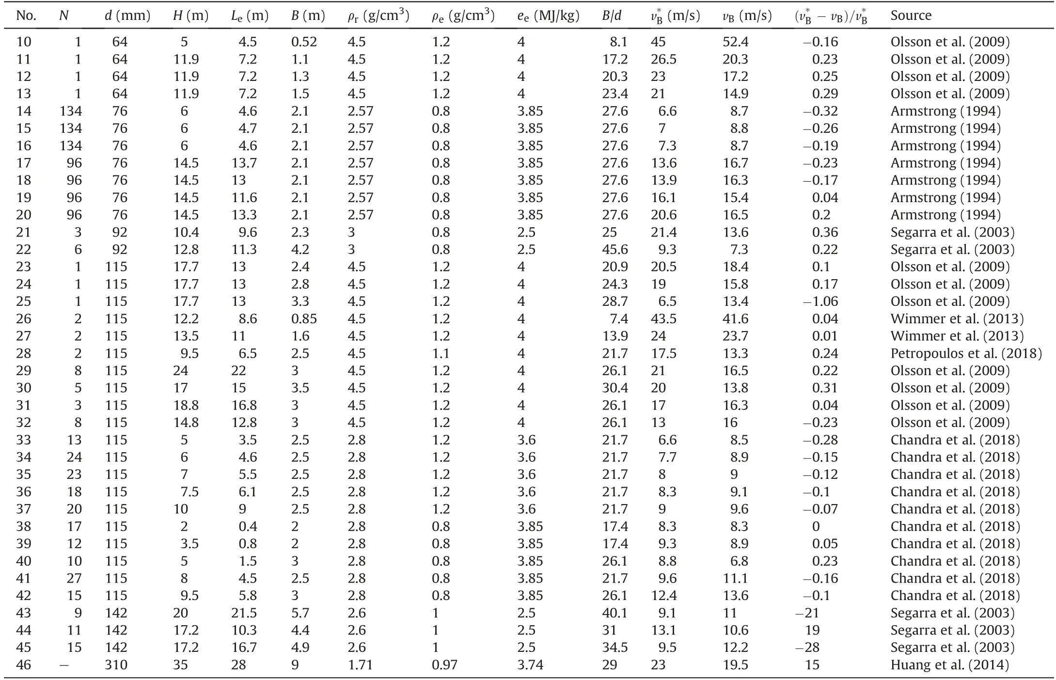
Table 2 Blast parameters, properties of rock and explosive,measured burden velocity and calculated burden velocity for Blasts 10-46.
In Fig. 3, four solid curves are also shown. These curves are drawn according to Eq.(6)using the parameters of blasts 11,38,43 and 46, respectively. These blasts have different blasthole diameters of 64 mm, 115 mm, 142 mm and 310 mm, respectively.Clearly, most measured burden velocities are close to their corresponding curves to a certain extent, indicating that Eq. (6) can predict the burden velocity of a full-scale blast.
Fig. 3 indicates that both measured and calculated burden velocities decrease with increasing ratio B/d.This is consistent with Eq.(6). In addition, Fig. 3 shows that at same or similar ratio B/d, the burden velocity varies significantly. For example, as B/d = 17.4 for Blasts 38 and 39,the measured burden velocities are 8.3 and 9.3 m/s and the calculated velocities are 8.3 and 8.9 m/s,respectively,with a maximum deviation of 5% between the measured and calculated burden velocities. As B/d = 17.2, close to 17.4, for Blast 11, the measured burden velocity is 26.5 m/s and the calculated one is 20.3 m/s,with a difference of 23%between these two velocities.This large variation of burden velocity at same or similar ratio B/d may be caused by other parameters in Eq.(6)in addition to the ratio B/d.

Fig. 3. Comparison of measured and calculated burden velocities at different ratios of B/d in all full-scale blasts.
4. Discussion
4.1. Quantity of blastholes in a blast
The above description demonstrates that Eq.(6)can predict the burden velocity of a full-scale multihole blast although it is based on a single-hole blast.The main reason is that in current full-scale blasts, the delay time between two adjacent holes is so long (usually such a delay time is equal to or greater than 25 ms in both surface and underground production blasts, but some mines may use a delay time of 17 ms between holes) that there is almost no interaction between two neighbouring blasting holes concerning their burden movement.In other words,the stress wave interaction between the two blasting holes with such a long delay time is negligible. Field measurements of underground mining blasts whose maximum explosive charge length was about 25 m showed that the wave length was less than 30 ms as the wave measurements were conducted at a place 90 m far from the blasting source(see Figs.1.25 and 1.26 in Zhang(2016a)).Considering that open pit mines often have much shorter charge length than 25 m and the 90 m distance in the case of Zhang (2016a), the wave length of a single hole in ordinary open pit blasts must be markedly shorter than 30 ms. Thus, the stress wave interaction between the neighbouring holes is not possible. For underground mining blasts with longer charge length than 25 m,the wave interaction between two adjacent holes may exist, but such wave interaction will be small and ignorable due to limited charge length (the maximum charge length may appear in sublevel caving where the charge length of the longest production holes may reach 40 m). In addition to the impossible stress wave interaction from two adjacent holes,the gas interaction from two adjacent holes is nearly impossible, either.This can be explained by the measured speed of gas propagation from a blasting hole to the surface of three granite models (Chi et al., 2019a, b), indicating that the speeds of gas propagation in the three rock specimens were 185 m/s, 240 m/s and 304 m/s,respectively.Using the minimum gas velocity of 185 m/s and taking 25 ms as the delay time between two adjacent holes, the gas can pass through a burden of 4.6 m within a time of 25 ms.In this case,if burden is smaller than 4.6 m, there will be no gas interaction between two adjacent holes;if burden is greater than 4.6 m,there will be gas interaction with increasing burden. However, such interaction will be limited since the burden cannot be increased to a very large value. In brief, both stress wave interaction and gas interaction are not possible or very small in ordinary full-scale blasts. As a result, Eq. (6) is valid for ordinary full-scale blasts.However, if the delay time between holes is very short in a fullscale blast, for example when electronic detonators with a few millisecond delay time are used, Eq. (6) should be modified.
4.2. Coefficient cB
The coefficient cBin Eq.(6)represents how much percent of the explosion energy is used to move the burden rock. Previous measurements indicated that the kinetic energy carried by moving burden varies from 3% to 12% (Ouchterlony et al., 2004) and from 3.3% to 39% (Sanchidrián et al., 2007). Considering these measurements,we tried to use cB= 0.12 in Eq.(6)and found that cB=0.12 was a reasonable value for ordinary full-scale blasts excluding those blasts with very short blastholes and/or too short stemming.Therefore,cB= 0.12 can be used to predict the burden velocity of an ordinary full-scale blast.
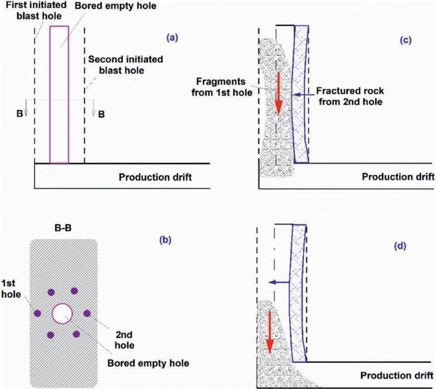
Fig.4. Opening slot in sublevel caving:(a)Vertical section of a production drift with bored large hole;(b)Cross-section of the large hole and six blastholes;(c)Fragments jammed due to too short delay time between first two blastholes; and (d) Fragments not jammed due to proper delay time.
Since each simultaneous blast has two holes in blasts 26-28,the value of cB= 0.08 is given to these three blasts.Table 2 shows that the calculated burden velocities of Blasts 26 and 27 are very close to the measured ones, meaning that cB= 0.08 is a suitable value for simultaneous two-hole blasting. However, the calculated burden velocity of blast 28 is smaller than the measured burden velocity by 24%.Note that Blasts 26 and 27 were fired by electronic detonators while Blast 28 by electric detonator. Therefore, 0.08 is suitable for two simultaneously fired holes with electronic detonators or exact initiation time,but a two-hole simultaneous blast using electric or non-electric detonators should use a value greater than 0.08 and less than 0.12 for cB.
For those short-hole blasts either with too short stemming or with small ratio of charge length to burden mentioned in Section 3.2,different cBvalues are given to different blasts. As a result, the calculated burden velocities are basically consistent with the measured velocities, meaning that these different cBvalues are suitable.Take stemming as an example,we can explain why different cBvalues are used for those blasts.As too short stemming is applied to a blasthole, all stemming is ejected out of the hole much earlier(compared with a normal size stemming), and then gases are escaping as the ejection occurs. This latter stage is similar to a blasthole without stemming.Laboratory model blasts showed that at least 25% explosion energy was wasted as blastholes were not stemmed concerning rock fragmentation,compared with the blasts with (partial) stemming (Zhang et al., 2020a). Underground mine blasts indicated that gas ejection from unstemmed blastholes was up to 50%explosive energy based on air pressure measurement close to the collars (Brinkmann,1990). Since a certain amount of explosive energy is wasted as ejected gases, the parameter cBshould be smaller than 0.12 if less stemming than that in ordinary blasts is used.
Since laboratory model blasts have more free surfaces than fullscale blasts, fragment throw may occur in more directions, in particular if the boreholes are very short.Accordingly,it is assumed that cB= 0.04 is appropriate to the model blasts. However, the discrepancy between the burden velocity calculated by Eq. (6) and that measured in the model blasts shown in Table 1 and Fig.2 is quite large,implying that cB= 0.04 may not be an apt value for the model blasts.In other words,the empirical formula being proposed may not be applicable to small-scale blasts because the mechanism in the small-scale blasts is different from that in the large-scale blasts.
4.3. Breakage angle θ
A simple spalling analysis indicated that the angle of breakage is equal to 2θ=120°in rock blasting(Zhang,2016a).In various model blasts,this angle was reported to be 2θ=100°-160°(Ouchterlony and Moser, 2013), and in small-scale field blasts, 2θ = 90°-120°(Noren, 1956). Concerning full-scale blasts, it was stated that the value 2θ = 90°was reasonable for engineering rock blasts(Olofsson, 1999). Based on the above description, this study employs 2θ = 90°for ordinary full-scale blasts and 2θ = 120°for laboratory model blasts. According to the calculated burden velocities using Eq.(6)and the measured burden velocities presented in Table 2 and Fig. 3, we can conclude that 2θ = 90°is suitable for ordinary full-scale blasts. Therefore, we recommend 2θ = 90°for ordinary full-scale blasts.
4.4. Applications and limitation
Prediction of burden velocity has many applications in tunnelling, mining and rock construction. In brief, burden velocity is necessary for determining (1) the delay time between adjacent holes or rows in an ordinary full-scale blast, (2) the delay time in the cut blast of tunnelling or drifting, (3) the delay time in the opening slot of underground mining, and (4) the delay time as a hanging roof is broken down in underground mining.
Let us take the opening slot in the Malmberget underground mine as an example(Fig.4).The bored empty hole has a diameter of 0.7 m and a total of six blastholes with a diameter of 115 mm surround the empty hole with a burden of 0.8 m. The other parameters concerning the blast design and properties of the ore mass and the explosive are: cB= 0.12,θ= 45°,ρe= 1.2 g/cm3,ee= 4 MJ/kg, ce= 0.8 and ρr= 4.5 g/cm3. Through inputting the values of these parameters into Eq. (6), we can obtain burden velocity vB= 57.6 m/s as B=0.8 m and d=115 mm.According to this burden velocity and the diameter of the empty hole, the fragments from the first-fired hole needs a time of 12 ms to collide with the wall of the empty hole. After the collision with the wall, the fragments will fall down.Only when all the fragments have fall out of the empty hole,the second hole can be fired.The minimum delay time between the first hole and the second hole should be 12 ms plus the falling time of the fragments from the first hole.If a delay time smaller than the minimum delay time is given between the first and the second holes,all or most of the fragments from the first hole will be jammed in the empty hole.As a result,the opening slot will fail and the blast-caused shock wave and stress waves will pass through the jammed fragments, resulting in high ground vibrations.This did occur in underground mining such as sublevel caving(see Fig. 24.15 in Zhang (2016a)) where an opening slot was failed due to too short delay time between first several holes.
In addition to the delay time discussed above, burden velocity can be used to estimate the kinetic energy carried with a moving burden. It has been found that the boulders from the first row are much more and greater than those from other rows in multirow blasting in open pit mines(Winzer et al.,1983;Olofsson,1999).One of the main reasons is that the fragments from the first row can fly freely(Zhang,2016a,2017).This free flight consumes much kinetic energy,which is one kind of energy waste,since during their flight,the kinetic energy contributes nothing to fragmentation.The above explanation is consistent with the production blasts by Aler et al.(1996) who reported that fragmentation had been improved with an increasing number of rows. Since the kinetic energy of flying fragments from any row except for the first one can be partly used in their secondary fragmentation via collision with the fragments from the nearest row, a blast with more rows will utilize more kinetic energy than a blast with fewer rows in the secondary fragmentation,resulting in better fragmentation in the former.To make full use of this kind of kinetic energy in a multirow blast, Zhang(2016a, 2017) recommended that a barrier to the first row in a multirow blast should be used. Recent model blasts demonstrated that a steel barrier to the free face of a number of rock blasting models had greatly enhanced their fragmentation, compared with either a blast without such a barrier to the free surface or a blast with a constrained surface (Chi et al., 2019b; Zhang et al., 2020b).Obviously, it was the barrier that made part of flying fragments broken again via their collision to the barrier in the model blasts.By using Eq. (6), we can estimate the kinetic energy carried with a moving burden so that a correct burden is chosen.For example,if a barrier is available,a relatively smaller burden may be employed,at least for the first row in a multirow blast.If so,the boulders can be reduced and the fragmentation can be improved in the blast.
As discussed earlier,Eq.(6)is developed under the condition of full explosive charge.Accordingly,Eq.(6)can be used to predict the burden velocity of a full-scale blast. However, this equation is not valid for a blast with a decoupled charge.To predict burden velocity in a blast with decoupled charge,Eq.(6)must be modified or a new formula should be developed. In addition, there is a great discrepancy between measured burden velocity and calculated one using Eq. (6) for small-scale model blasts, meaning that Eq. (6) is not suitable for small-scale model blasts.
For full-scale blasts, how to choose values of coefficient cBand breakage angle θ in Eq. (6) has been described and discussed in Sections 3.2, 4.2 and 4.3 in detail. The users can decide these two values by following the procedure there, and then they can estimate the burden velocity by using the values and other parameters in Eq.(6).If possible or necessary,the users may also perform back analysis based on a few trial blasts and modify the coefficient cBand breakage angle θ as suggested in this paper.
5. Conclusions
A theoretical relation between the burden velocity vBand the ratio of burden B to borehole diameter d is developed,in the form of vB∝(B/d)-1. This relation is consistent with the measurement results from full-scale or production blasts in both surface and underground mines.Therefore,this relation is suitable for full-scale or production blasts with fully-coupled explosive charge.To estimate the burden velocity of an ordinary production blast, the values of cB= 0.12 and θ=45°are recommended.For other full-scale blasts,for example with too short blastholes or too small stemming length, θ = 45°is recommended but the value of cBshould be determined according to the actual blast design by referencing the procedure in Section 3.2.
This theoretical relation is not developed under the condition of a decoupled explosive charge,thus it should not be valid for a blast with decoupled explosive charge.To be valid for decoupled charge,further study is necessary. In addition, this relation is not well suitable for laboratory small-scale blasts. To be suitable for smallscale blasts, this relation needs more model blasts to modify.
Declaration of competing interest
The authors declare that they have no known competing financial interests or personal relationships that could have appeared to influence the work reported in this paper.
Acknowledgments
The authors are grateful to Dr.Ruilin Yang for providing relevant publications.
 Journal of Rock Mechanics and Geotechnical Engineering2021年4期
- Journal of Rock Mechanics and Geotechnical Engineering的其它文章
- Discussion on“Analysis of Bingham fluid radial flow in smooth fractures”[J Rock Mech Geotech Eng 12 (2020) 1112-1118]
- Validity of continuous-failure-state unloading triaxial tests as a means to estimate the residual strength of rocks
- Hydromechanical behaviors of andesite under different stress states during fluid injection
- Performance of identical rockbolts tested on four dynamic testing rigs employing the direct impact method
- Influence of grain size on strength of polymineralic crystalline rock:New insights from DEM grain-based modeling
- Geomechanical model test for analysis of surrounding rock behaviours in composite strata