Signal-recycled weak measurement for ultrasensitive velocity estimation∗
Sen-Zhi Fang(方森智), Yang Dai(戴阳), Qian-Wen Jiang(姜倩文),Hua-Tang Tan(谭华堂), Gao-Xiang Li(李高翔), and Qing-Lin Wu(吴青林)
Department of Physics,Central China Normal University,Wuhan 430079,China
Keywords: quantum optics,weak value,recycling
1. Introduction
Weak value amplification, which was originally introduced by Aharonov, Albert, and Vaidman in 1988,[1]has shown its outstanding performance in precise measurements.By preparing appropriate pre-and post-selected states of a system,one can obtain a significantly amplifying signal in meter distribution. It has been successfully used to achieve many sensitive physical effects,such as beam deflections,[2,3]phase shift,[4–7]spin Hall effect of light,[8]ultralow velocity,[10,11]angular rotations,[12–14]and temperature measurements.[15–17]In this article,we focus on the weak value amplification setup used in Ref.[10],which couples the velocity of a piezo-driven mirror to the“which-path”modes of a Michelson interferometer. The meter corresponds to the arrival time of output light from the dark port of the interferometer.
The common disadvantage of standard weak-value-based metrology is that only a small part of information of the incident beam is used, while most information is lost during the post-selection process. Therefore, this technique is also thought as a method that concentrates finite Fisher information of measured parameters on a fraction of events.[18–20]There is plenty of doubt whether the weak value amplification can increase the ultimate limit of measurement precision.[18,21,22]With regard to probe loss by post selection, researchers have put forward the power recycling technique, which is initially applied in the detection of gravitational waves.[23,24]The aim is to reuse the discarded events by placing a partially transmitting mirror at the bright port of interferometer. This has also been demonstrated and can be used to effectively improve the ultimate signal-to-noise ratio of beam deflections in both theory and experiment.[25–27]Here we propose a signal recycling scheme, which places a partially transmitting mirror at the dark port of an interferometer,to overcome the shortcoming of post-selection.
2. Interferometric weak value measurement
We have already known from Ref.[10](see Fig.1,in the absence of partially transmitting mirrorMp) that light entering into the Michelson interferometer is a non-Fourier limited Gaussian pulse,

where we have assumedkvτ ≪φ ≪1,Nis the normalized average photon numbers per unit time,τis the modulated pulse width,vis the velocity of moving mirror,φis the near destructive interferometric angle, andk=2π/λis the wave number of laser.


whereNdet=Nφ2is the number of detected photons.
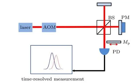
Fig. 1. Schematic of weak-value velocity measurement with signal recycling technique. The beam is modulated as a Gaussian shaped pulse by an AOM(acoustic optical modulator)and then enters into the Michelson interferometer,which is turned slightly off destructive interference by a small angle 2φ. The piezo-drven mirror (PM) is moving with a low velocity v, which is hopeful for precise measurement. The majority of light would be reflected back and a small amount is collected by thephoto detector(PD),and the arrival time of light is measured with a time-resolved measurement module. We note the orientations of reflected and detected light as bright and dark port of the interferometer,respectively. In the presence of the partially transmitting mirror Mp,the light at the dark port would be reflected and cycled.
3. Signal recycling
In our signal recycling scheme, we form a resonant cavity by introducing a partially transmitting mirror. Unlike the power recycling weak value scheme[25–27,31]in which the partially transmitting mirror is at the bright port,here we place the mirror at the dark port of the Michelson interferometer,i.e.,in front of the detector. We will show that this cavity in our signal recycling scheme can also improve the number of detected photons and the corresponding SNR like the power recycling scheme.

Fig. 2. Schematic of a resonant optical cavity formed by two partially transmitting mirrors. Under the condition of the resonant cavity, the reflected amplitude Er is exactly zero and the amplitude leaving the cavity through the second mirror Eout becomes equal to the input amplitude E0.

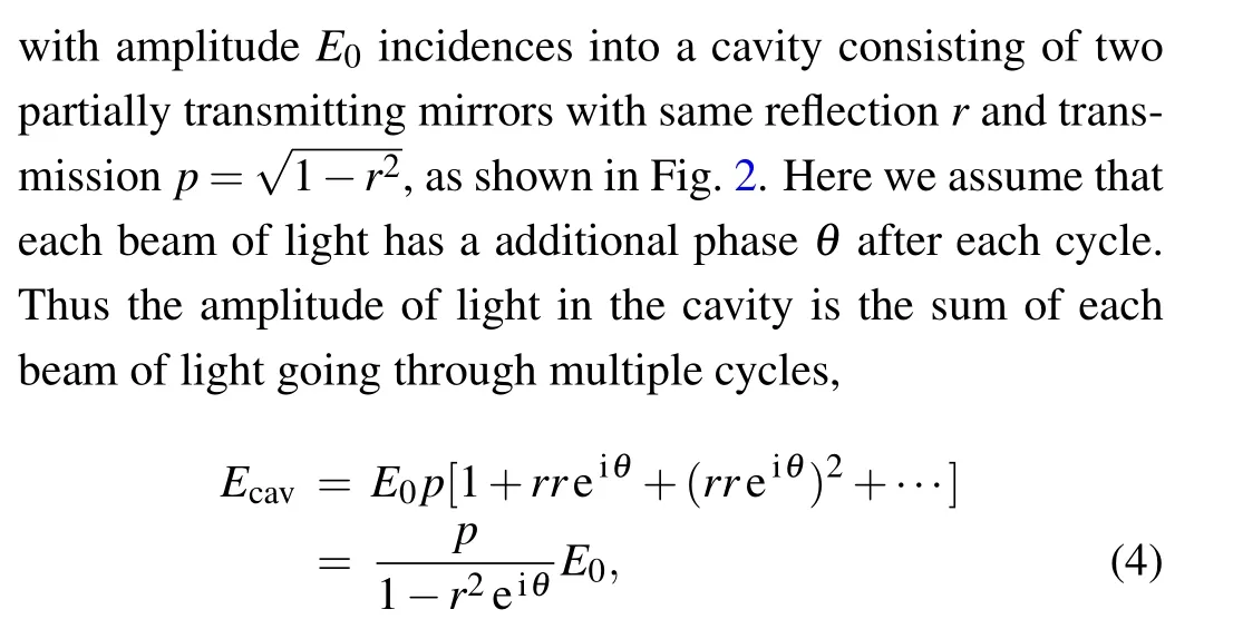
and the amplitude of light reflected back the laser is the sum of light reflected by the first mirror and reflections inside the cavity

We note that the amplitude of outgoing light from the cavity is

Under the condition of resonant cavity,the phase addition every cycle isθ=2πn,wherenis an integer. Thus we find the amplitude of reflected light is zero and the outgoing light is equal to the initial incident light. The light in the cavity has a gain where we have made a series expansion of


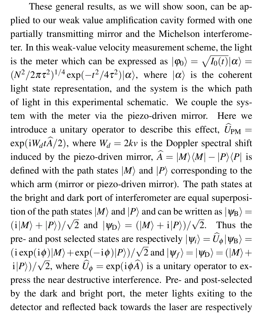


and abandoned higher orders under the conditionkvτ ≪φ ≪1 andcτ ≫lλ >2nmaxlcav. The parameterφ1is

Thus the steady state amplitude of detected light is


We are interested in the time shiftδt2where the velocity is included, andδt3is a constant time delay which does not influence our measurement. Thus the intensity of detected light is


4. Comparison with standard weak measurement
We now compare these results with standard weak measurement. From Eq.(17)we can easily obtain the number of detected photons and the signal-to-noise ratio of velocity in this signal-recycled scheme


If the loss of system is also considered in the standard scheme,we can have the factors about improvements of detected photons and SNR as follows:

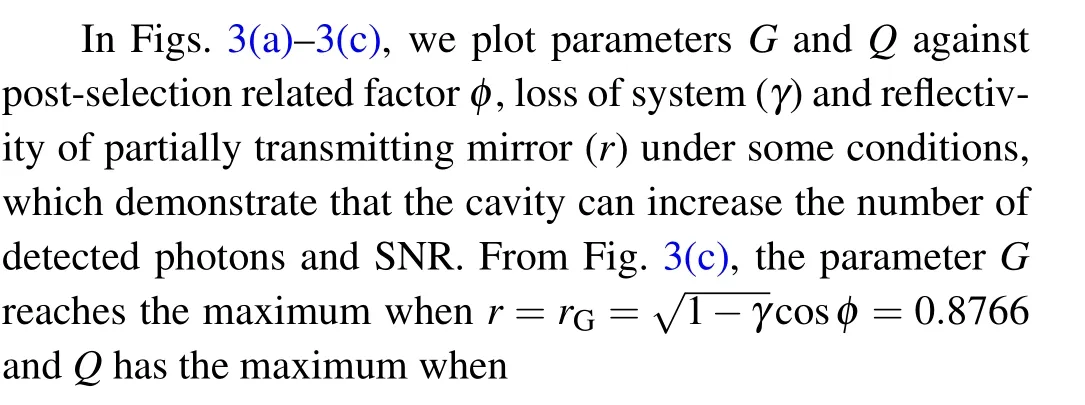
which indicate that we cannot simultaneously reach the optimal improvements of detected photons and information about the velocity. Equation(21)can be written as


Fig.3. The parameters G(red,solid)and Q(blue,dashed)versus φ,γ and r:(a)φ is between 0.1 and 0.3,and r=0.9,γ=0.2;(b)γ is between 0 and 0.4,and r=0.9,φ =0.2;(c)r is between 0 and 1,and φ =0.2,γ =0.2.
The coefficient

which means that the time shiftδt2in the signal-recycled scheme is smaller than that in the standard weak value measurement. This is owing to the walk-off effect because the time shift of a small fraction of light exiting to the dark port is forward or backward, which causes a complementary shift in the opposing direction for the light exiting to the bright port.We now simply explain this effect.

Fig. 4. Walk-off effect in the signal-recycled scheme: (a) f(t) (red,solid), fT(t) (blue, dashed) and fR(t) (black, dotted); (b) n=0 (red,solid),n=1(blue,dashed),n=2(black,dotted),n=3(purple,dashdotted).


5. Comparison with power recycling weak measurement
We now compare the signal recycling scheme with the power recycling scheme.[31]Since the detected light in the signal recycling scheme is the same as that in the power recycling scheme,we now focus the light reflected back to the laser and in the cavity. It is easy to calculate the reflected light in the signal recycling scheme as follows:

and the reflected light in the power recycling scheme is

in the signal recycling and power recycling schemes. Similarly,the amplitudes of light in the cavity are,respectively,

in the signal recycling and power recycling schemes.
When the reflectivity of the partially transmitting mirror isr=rG,i.e.,the intensity of detected light reaches the maximum,we can obtainYrp=0 andYrs>0.We plotYrs,Ycs,Ycpin Fig.5 forr=rGunder some conditions. When the reflectivity of the partially transmitting mirror isr=rQ,i.e.,the signal-tonoise ratio of detected light is maximal,we showYrs,Yrp,Ycs,Ycpin Fig.6 under some conditions. It is easy to see that the intensity of the reflected light is stronger and the light in the cavity is weaker in the signal recycling scheme than those in the power recycling scheme.
Now we consider the reflected light as the cavity locking signal like Ref.[32],where the Pound–Drever–Hall technique plays a critical role.[33–35]Thus we need not place a beam splitter at the detecting port like Ref.[27]and the collectiondetection efficiency can be improved. Equations(24)–(27)are an approximation for a Gaussian pulse but exactly accurate for a stable wave. Here we directly use the Pound–Drever–Hall analysis in the supplemental material of Ref. [27]. If a reference beam with a phase modulation by the angular frequency ofΩis used to control the cavity length, then the reflected light is

Fig. 5. Reflectivity of the partially transmitting mirror, r = rG =: (a) Yrs (red solid), Ycs (black dotted), Ycp (purple dashdotted)versus φ for γ =0.2; (b)Yrs (red solid),Ycs (black dotted),Ycp(purple dash-dotted)versus γ for φ =0.2.

Fig.6.Reflectivityofthepartiallytransmittingmirror,r=rQ=(a)Yrs(redsolid),Yrp(bluedashed),Ycs(blackdotted),Ycp(purple dash-dotted)versus φ for γ =0.2;(b)Yrs (red solid),Yrp (blue dashed),Ycs (black dotted),Ycp (purple dash-dotted)versus γ for φ =0.2.

whereais a constant,E0is the amplitude of laser,ω0is the angular frequency of the laser,αis the modulation depth,andg(ω)is denoted as

Fig.7. The error signal Sr (blue dashed)and St (red solid), in units of wavelength λ in the horizontal axis: (a) the power recycling scheme,(b)the signal recycling scheme.
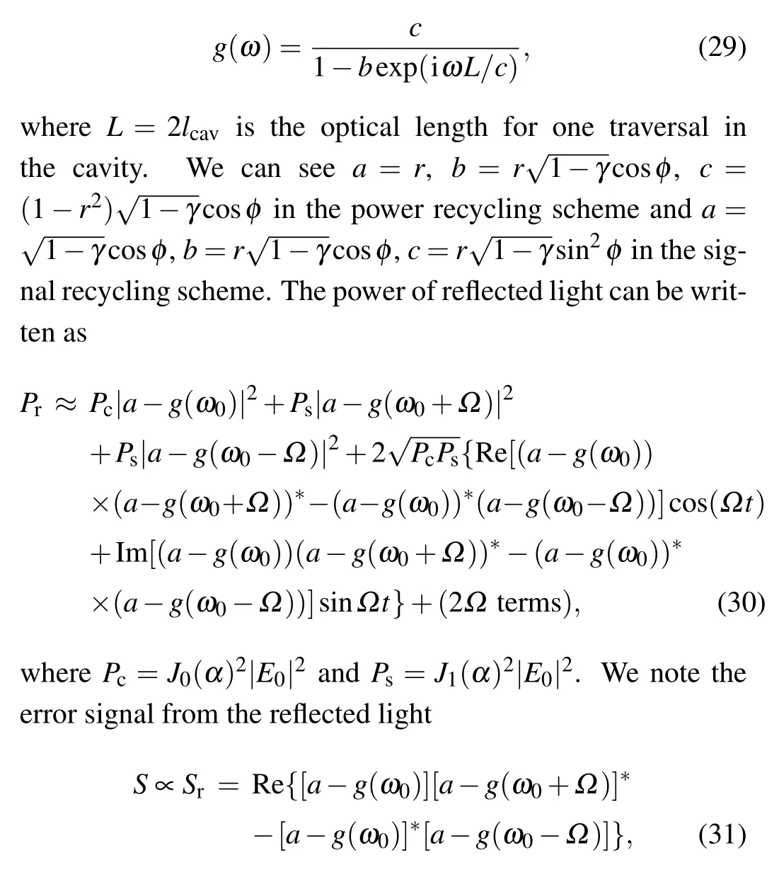
while the error signal from the detected light is


6. Conclusions
We have proposed a signal-recycled technique to increase the intensity of the outgoing light of the standard-weak-valuebased velocity measurement system. Like the power-recycled scheme, the cavity formed by the Michelson interferometer and the partially transmitting mirror can increase the SNR of velocity estimation compared to the standard weak measurement. However, optimal improvements of detected photons and SNR cannot be obtained simultaneously owing to the walk effect.Moreover,we find that the reflected light is stronger and the light in cavity is weaker compared with those in the power recycling scheme,which may increase the collection-detection efficiency in prospective relevant experiment.
- Chinese Physics B的其它文章
- Quantum computation and simulation with vibrational modes of trapped ions
- ℋ∞state estimation for Markov jump neural networks with transition probabilities subject to the persistent dwell-time switching rule∗
- Effect of symmetrical frequency chirp on pair production∗
- Entanglement properties of GHZ and W superposition state and its decayed states∗
- Lie transformation on shortcut to adiabaticity in parametric driving quantum systems∗
- Controlled quantum teleportation of an unknown single-qutrit state in noisy channels with memory∗

