
Artificially frozen ground and related engineering technology in Japan
2021-05-31 08:08SatoshiAkagawa
Satoshi Akagawa
Cryosphere Engineering Laboratory,Tokyo,Japan
ABSTRACT Since the 1970's,frozen ground has been developing near the Tokyo Bay area around liquefied natural gas(LNG)in‐ground storage tanks.For disaster prevention purposes,the tanks are constructed below the ground surface.Since the tem‐perature of the liquid stored in the tanks is−162°C the soil surrounding the tanks freezes.Since this frozen ground has ex‐isted for almost half a century,we have permafrost near Tokyo.The development of artificial frozen ground may cause frost heaving,resulting in frost heave forces that may cause structural damage of adjacent LNG in‐ground storage tanks.Therefore,the demand for frozen ground engineering increased and consequently we now have advanced technology in this area.Fortunately,we use this engineering technology and artificial ground freezing for civil engineering,especially in big and crowded cities like Tokyo.This paper provides a summary of the testing apparatus,test methods,and assessment methods for frost heaving.
Keywords:artificial ground freezing;frost heave;frozen ground engineering
1 Introduction
At present,permafrost can be found near the To‐kyo Bay area.This permafrost is actually artificially frozen ground,which started to develop around lique‐fied natural gas(LNG)Ⅰn‐ground Storage Tanks(here‐inafter called LNG in‐ground tanks)that have stored LNG at−162°C since the 1970's.Since then,more than 80 LNG in‐ground tanks have been constructed,resulting in a few hundred thousand cubic meters of artificially frozen ground.
Since the LNG in‐ground tanks were constructed close to each other as presented in Figure 1,engineers recognized that potential damage could resulted from freezing soil pressure pushing adjacent LNG in‐ground tanks against each other,and technologies to evaluate and manage the freezing earth‐pressure be‐came crucial.Therefore,frozen soil engineering tech‐nology advanced considerably from the 70's to the 90's in Japan.Ⅰn this article,empirical facts,currently somewhat forgotten in the frost heave research com‐munity,will be briefly discussed along with activities of artificial ground freezing in Japan.
2 Frost heaving
There are records of ground upheaval during win‐ter freezing,and ground settlement during spring thawing,in northern Europe in the 17th century.Ⅰn the middle of the 18th century,E.O.Runeberg(1765)reported general information on the phenomenon named"Frost Heaving";at which time the phenome‐non started to be recognized among people.
From the beginning of the 20th century,representa‐tive research focused on frost heaving advanced with re‐search activity of the SwedishⅠnstitute of Roads,and the paper by Beskow(1935).During the same period,research on frost heave started in the U.S.A.as related to road,railroad,and construction engineering,as de‐scribed by Taber(1929,1930).Black and Hardenberg(1991)compiled these initial three papers,and included research history up to 1990's.One remarkable effort is the translation of Beskow's(1935)Sweden paper,by Black and Hardenberg(1991).Therefore,Black and Hardenberg(1991)is an excellent source from which to learn thepioneering work of frost heave research.
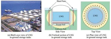
Figure 1 LNGⅠn‐ground Storage Tanks used near the Tokyo Bay area
2.1 Difference between "in situ freezing" and"segregation freezing"
As reported by Beskow(1935),Runeberg(1765)concluded that frost heaving is caused by the nine per‐cent volumetric expansion of pore water while freez‐ing(herein after"in situfreezing").On the other hand,Johansson(1914)explained that frost heaving is caused not only byin situfreezing but also by a mechanism in which segregated ice forms when pore water or unfrozen water migrates from unfrozen ground to the warmest,growing ice lens.This process is widely accepted among current researchers and is called"segregation freezing"(Takagi,1979).
2.2 Thermal regime and stress-strain field while freezing
Segregation freezing is a phenomenon where pore water is driven from unfrozen soil to a segregating ice lens and changes its phase to solid ice.The pore water pressure at the growing ice lens surface should be low‐er than that of unfrozen soil.Ⅰf this assumption is cor‐rect,consolidation is expected in front of the growing ice lens.Akagawa(1998 and 1990)examined the strain distribution of freezing soil along with the soil thermal regime utilizing X‐ray radiography(Figures 2a,2b)and image processing and analysis technologies.
Ⅰn this study,a frost‐susceptible alluvial clay was used as the test specimen,with a diameter of 60 mm and initial height of 95 mm.Fifteen lead spheres,each with a diameter of 1.5 mm and into which a thin thermocou‐ple was inserted,were placed near the central line of the columnar specimen as in Figure 2c.X‐ray radiographing was conducted every hour in the first twenty‐four hours with reduced frequency as time elapsed,as shown in Figure 2e.For every X‐ray radiographing,two radio‐graphs were taken from different X‐ray source loca‐tions,as shown in Figure 2b,in order to conduct a three‐dimensional lead sphere coordinate analysis.
The temperature of the lead spheres was acquired as shown in Figure 2d along with the heave amount with elapsed time.Also,the vertical coordinate of the fifteen lead spheres was acquired with time as shown in Figure 2e.Using the temperature data and vertical coordinates,the exact temperature profiles during each X‐ray radio‐graph were constructed as shown in Figure2f.
By comparing temperature profiles and X‐ray ra‐diographs,the temperature of the actively segregating ice lens surface was found to be considerably lower than the water freezing temperature at the standard condition as shown in Figure 2g.Since this result was obtained with no assumptions,the existence of what is called the"frozen fringe"was confirmed experi‐mentally.The existence of the frozen fringe also was confirmed through a different method and with differ‐ent material,i.e.,welded tuff(Akagawaet al.,1988).
The strain distribution of the freezing specimen was analysed using the vertical coordinate data of all the lead spheres.Figure 2h contains some of the re‐sults,in which negative strain that corresponds to con‐solidation is clearly seen in the area of the frozen fringe and unfrozen soil.Therefore,the assumption postulated by Chamberlain and Gow(1978)−i.e.,"…the frozen fringe and the adjacent unfrozen section should be consolidated while freezing,due to the rise of effective pressure,which was caused by the depres‐sion of the pore water pressure for sucking pore water from the unfrozen side"−was confirmed with this ex‐periment.This behavior is now well known,especial‐ly when normally‐consolidated soil freezes,but it is negligible when over‐consolidated soil freezes.This behaviour is supported by soil mechanics.The knowl‐edge that consolidation happens during freezing of normally‐consolidated soil has been used in cold re‐gions because winter earth work accelelates soil con‐solidation by freezing(Akagawa,1997).Ⅰn addition,the depression of pore water pressure at the segregat‐ing ice lens was measured directly in frost heave tests(Miyataet al.,1994).

Figure 2 Thermal regime and stress‐strain field during frost heave test
2.3 Definition of ice lens
The technical term"ice lens"is not only defined by its lens‐like shape but also defined by the unique shape of an ice monocrystal and the arrangement of the monocrystals relating to the heat flow direction(Penner,1961).This is visualized in Figure 3a(Ak‐agawa,2016).This image was taken with orthogonal‐ly‐polarized light,which passed through a frozen thin section 1‐mm thick.The black areas in the photo‐graph represent the frozen soil and the vertical col‐ored columns represent individual monocrystals with‐in the ice lenses.The elongated direction,i.e.,vertical direction,corresponds to the heat flow direction.Fig‐ure 3b is an image of the ice lens section normal to that shown in Figure 3a.
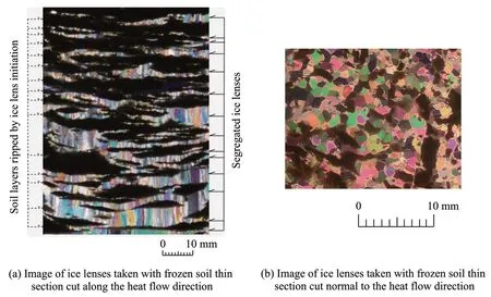
Figure 3 Shape of the monocrystals of ice lenses observed with orthogonally‐polarized light
As is clearly seen in the photo,each independent color represents ice monocrystals and their polygonal shapes indicate that an ice lens is composed of ice monocrystals,which are pencil‐shaped and aligned along the heat flow direction.These photographs clearly indicate what Penner(1961)defined.There‐fore,it is important to confirm the above‐mentioned ice monocrystalline structure before using experimen‐tal data for precise research on the ice lens segrega‐tion mechanism.
3 Frost heaving in engineering
Research on the frost heave mechanism has a long history and significant scientific results.Unfortunate‐ly,there is still no result that can provide frost heave susceptibility quantitatively.Therefore,the frost heave test procedure has been standardized,which in‐cludes how to use frost heave test results for the quan‐titative frost heave prediction under any kind of freez‐ing conditions.The following briefly explains the standard test method.
3.1 Frost heave test
Frost heave testing has improved worldwide over the years.Chamberlain(1981)compiled a summary of attempts to improve frost heave test apparatus in North America and Europe.Starting in the 1940's,Ukichirou Nakaya of Hokkaido University and his group started frost heave tests,and starting in the 1960's Tsutomu Takashi of Seiken Co.Ltd.and his group conducted many frost heave tests,and proposed a practical frost heave test method and an empirical formula,which handles test results well.Construction of LNG in‐ground storage tanks in Japan began in the 1970's,applying Takashi's useful achievement.Con‐current with the LNG in‐ground storage tank construc‐tion,artificial ground freezing technology improved greatly through hundreds of construction experiences in built‐up areas like Tokyo.One reason for this im‐provement was strict requirements for frost heave and thaw settlement management.Finally,in 2003 the Jap‐anese Geotechnical Society established a standard,which includes instructions on how to conduct frost heave tests and how to use the test results for quantita‐tive frost heave prediction.3.1.1Frost heave tests in Japan
As was mentioned earlier,in Japan there is now a standard way to define frost heave susceptibility of soil and how to use test results quantitatively.The name of the standard is"Test Method for Frost Heave Prediction of Soils"(JGS 0171‐2009).The standard provides:(1)the objective,(2)definition of technical terms,(3)required specifications of test apparatus,(4)specimen preparation procedure,(5)test procedure,and(6)data analysis method.
Figure 4 is a schematic drawing of the frost heave test apparatus introduced in the standard.The structure and functions shown in the drawing are similar to other apparatus.The specimen is sandwiched between two porous plates,which supply or drain water to or from the specimen.The two plates also serve as the upper and lower cooling plates,which work as cooling devic‐es and also contain pore water supply tubes.The upper cooling cylinder,specimen,and bottom cooling plate are covered with an acrylic cell.The acrylic cell is firm‐ly fixed to the bottom cooling plate whereas the upper cooling cylinder has an O‐ring to prevent water leakage and to ensure smooth sliding between the upper por‐tion of the acrylic cell and the upper cooling cylinder.

Figure 4 Schematic drawing of frost heave test apparatus shown in JGS 0171
With this set up,the specimen is frozen from the bottom up,in order to prevent adfreezing at the inter‐face between the upper cooling cylinder and inner sur‐face of the upper part of the acrylic cell.Otherwise,if the specimen is frozen from the top down,adfreezing will bind the acrylic cell and the upper cooling cylin‐der and/or frozen portion of the specimen.Ⅰn this situ‐ation,the frost heaving force generated in the freezing specimen is firmly confined by the upper cooling cyl‐inder and the bottom cooling plate,resulting in a high confining pressure that restricts the frost heave amount.
3.1.2Thermal shock
"Thermal shock"is a technique required to initiate constant freezing rate frost heave tests in order to pre‐vent super‐cooling.The technical term thermal shock is not popular among soil engineers,who sometimes encounter their own"thermal shocks"as a result.Our procedure is explained here in order to reduce readers'"thermal shock";however,the procedure may not be consistent due to differences in the thermal condition of each frost heave test apparatus.Again,the main purpose of the thermal shock is to secure nucleation of ice at the initial stage of the frost heave test.
Ⅰn our example,we first circulate 0°C brine to the cap(or the upper cooling cylinder)and the pedestal(or the lower cooling plate or cylinder),to chill the specimen temperature close to 0°C.After the speci‐men temperature becomes close to 0°C,we cease the circulation to the Tc side,which is the side from which freezing is initiated,and change the tempera‐ture of the low temperature thermostatic bath to−10°C.After the brine temperature becomes−10°C,then ther‐mal shock is initiated by circulating the−10°C brine to Tc side cap or pedestal.This is indicated by the steep temperature drop of Tc shown in Figure 5.Dur‐ing this steep temperature drop,super‐cooling is oc‐curring and ice nucleation has not yet started.Within 10 minutes,the Tc stops decreasing and starts increas‐ing to the freezing point of the pore water,as indicat‐ed in Figure 5.This is the evidence that ice nucleation has started and indicates the end of the thermal shock.Some expansion of the specimen and/or slight pore water expulsion occurs(Figure 5),which is evidence of ice nucleation.
3.1.3Improved frost heave test apparatus 1)Specimen Diameter
Depending on the particle size of the specimen,three different frost heave test apparatus are used at Hokkaido University.Figure 6a is the smallest frost heave test apparatus with a specimen diameter of 50 mm.This is good for clay and silt.The apparatus shown in Figure 6b has a specimen diameter of 60 mm,and is good for clay,silt,sand,and small gravel up to 10 mm.The largest frost heave test apparatus shown in Figure 6c has a cell diameter of 200 mm,and can handle frost heave tests of ballast.

Figure 5 Typical freezing side temperature(Tc)history during thermal shock
At Hokkaido University,all the frost heave test ap‐paratus is placed in cold rooms with temperatures con‐trolled at 1°C,which reduces the lateral heat flux to the specimen.Although the apparatus is within a 1°C cold room,the room temperature fluctuates due to de‐frost sequences.Thus,in order to minimize the lateral heat flow to the specimen,the frost heave test appara‐tus shown in Figure 6b has dual acrylic cells.The dou‐ble cell system is effective in reducing any tempera‐ture fluctuations.
2)O-rings
Another advantage of the apparatus shown in Fig‐ure 6 is that their caps and pedestals have O‐rings that allow bi‐directional freezing of the specimen.Ⅰn this case the inner surface of the acrylic cylinder has been machined to ensure a perfect cylindrical diameter.The frost heave test apparatus shown in Figure 6b is also used at the University of Alaska Fairbanks and the Cold and Arid Regions Environmental and Engi‐neeringⅠnstitute for precise frost heave experiments.
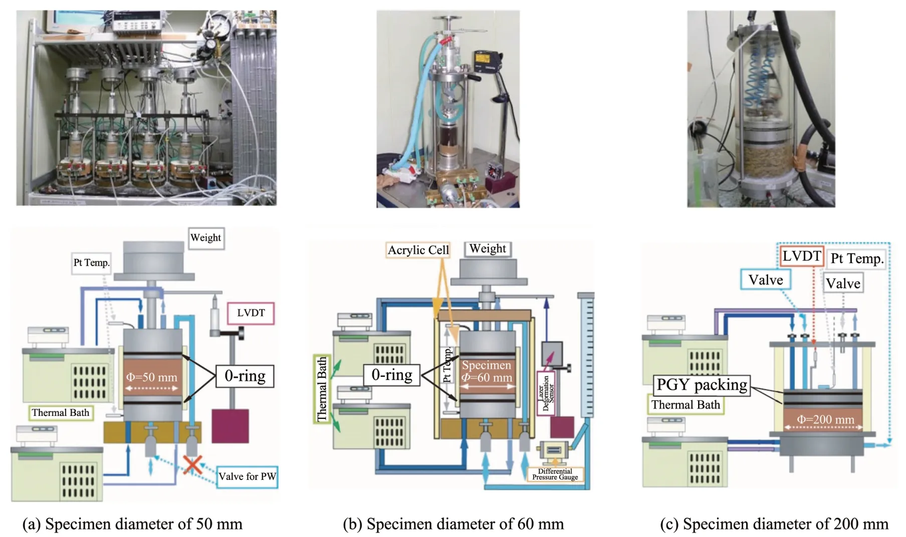
Figure 6 Ⅰmproved frost heave test apparatus
3)Frictionbetweeninnersurfaceof acrylic cell and O-ring
Recently,we conducted triaxial frost heave test with specially‐designed stacked acrylic rings,as shown in Figure 7(Amanumaet al.,2017).This cell consists of stacked acrylic rings connected with soft silicon rubber plates.Therefore,the frost heave pres‐sure normal to the heat flow is able to be monitored as the hoop strain of each acrylic ring independently by strain gauges.The height of each acrylic ring is 10 mm and the thickness of the silicon rubber plate is 1 mm.

Figure 7 Frost heave test cell for monitoring lateral heave pressure
Figure 8 is a plot of data obtained with this sys‐tem.Since the temperature of each acrylic ring is monitored with a thermocouple and the hoop stress with a strain gauge,the frost heave pressure normal to the heat flow and as a function of temperature can be plotted for each acrylic ring.The data in Figure 8 indi‐cate that the lateral pressure in the frozen side increas‐es as temperature decreases.The lateral pressure in the unfrozen side remains at zero.This implies that the side friction in unfrozen side of the specimen while freezing is negligible.Also,there is no friction in the frozen side of the specimen because of adfreeze bonding between the specimen and acrylic rings.
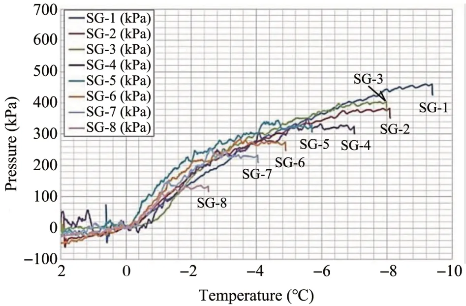
Figure 8 Lateral expansion pressure change with temperature
3.1 How to use test results for quantitative frost heave prediction
The boundary temperature fixed frost heave test is one sort of model test in which the freezing speed de‐crease with time;however,there was no method to ap‐ply the test results to engineering in the 1970's.By the mid‐1980's,there was a proposed method to use the test results of the step temperature change frost heave test as the model test(Akagawa,1985).
Around the same time,Takashiet al.(1978)devel‐oped a method to use test results as an index test for engineering purposes.Following their pioneering work,all engineering involving frost heave issues in Japan,including LNG in‐ground storage tanks and ar‐tificial ground freezing,have used Takashiet al.'s(1978)proposed empirical formula as detailed in Fig‐ure 9 and in Equation(1).Details of this procedure are described in JGS 0171‐2009,which is compiled in"Laboratory Testing Standard of Geomaterials Table of Contents,Vol.3"and is available at https://www.jiban.or.jp/e/standards/jgs‐standards/.
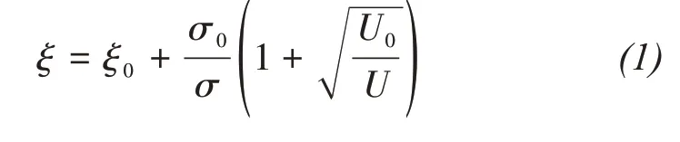
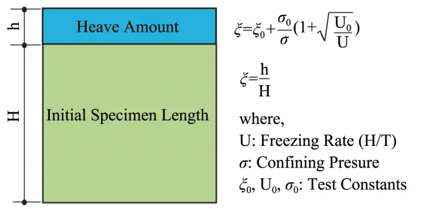
Figure 9 Engineering treatment of frost heaving by Takashi et al.(1978)
4 Practical use of frozen ground engineering
Ⅰn this section,a brief description of frozen soil engineering conducted in Japan is provided.
4.1 LNG in-ground storage tanks
There are more than 60 large LNG in‐ground stor‐age tanks near the Tokyo Bay area.The largest one is 72 m in diameter and 62 m in depth.The storage tank consists of reinforced concrete for which the inner sur‐face is covered with thermal insulation and a stainless steel membrane(Figure 1).Since the temperature of LNG is−162°C,the surrounding ground freezes,of‐ten causing frost heaving that pushes on the surround‐ing structures(Goto and Ryokai,1980;Gotoet al.,1985).To control frost heaving,all of the in‐ground tanks have what is called a"heat fence",which con‐sists of vertical heating pipes aligned in a concentric circle around the tank to increase the temperature of the surrounding ground.The thickness of the frozen ground around the tank can be controlled within a few meters by changing its temperature.Detailed informa‐tion about LNG in‐ground tanks is available at http://www.netdecheck.com/en/lngtech/ug‐tank/index.html.
4.2 Artificial ground freezing
Since 1962,artificial ground freezing has been conducted more than 700 times in Japan,with the total volume of artificially‐frozen ground around 0.7 million cubic meters.Most of the cases involve ar‐tificial ground freezing in densely populated areas such as Tokyo and Osaka.One of the most sophisticated artificial ground freezing sites,i.e.,the Trans‐Tokyo Bay Expressway,and an exceptionally large artificial ground freezing site,i.e.,the Fukushima Daiichi Arti‐ficial Ground Freezing for Water Shielding,are de‐scribed briefly.
1)Trans-Tokyo Bay Expressway
The traffic situation in Tokyo became congested in the 20th century.As a result,many expressways were constructed in metropolitan Tokyo with shield tunnel boring machines(TBM).The Trans‐Tokyo Bay Expressway is the one of the biggest and most complicated construction projects using artificial ground freezing.The expressway connects Kanaga‐wa Prefecture and Chiba Prefecture through 9.5 km of undersea tunnel and 4.4 km of above‐sea bridges as shown in Figures 10a,10c.The inner diameter of the tunnel is 11.9 m as shown in Figure 10b.Eight shield TBMs were launched through artificially fro‐zen ground that was developed around vertical shafts where the TBMs were assembled as shown in Figure 10c.Four pairs of TBMs started excavating along four different tracks,advanced toward each other and finally meeting after the scheduled tunneling.Fi‐nally,they were disassembled deep undersea in the artificially‐frozen ground.

Figure 10 Trans‐Tokyo Bay Expressway(https://www.tunneltalk.com/Japan‐Aug1994‐Trans‐Tokyo‐Bay‐Highway.php)
This project required 12 artificial ground freezing construction sites,and large volumes of artificially‐frozen ground were successfully managed.All of the artificial ground freezing was conducted by a subcon‐tractor who started the project using Equation(1).De‐tailed information of this project is available at"form_touketsu@seikenn.com".
2)Fukushima Daiichi Artificial Ground Freezing for Water Shielding
After the Fukushima Daiichi nuclear disaster,nucle‐ar pollutant leaked from the basement of the reactors.Ⅰn order to cease the leakage,several measures were intro‐duced,as shown in Figure 11.One of the measures named"Land‐sideⅠmpermeable Frozen Wall"used ar‐tificial ground freezing.The frozen ground wall sur‐rounds four reactors,with a length of 1,500 m and depth of 30 m.Ⅰt consists of 1,568 freezing pipes,and ground temperature monitoring pipes are installed every 5 m along the freezing pipe array.Monitored ground tempera‐ture data indicates that the volume of the wall is now about 0.3 million cubic meters and the wall is completely shielding the inflow of the ground water.Details of this site are available at https://fpcj.jp/wp/wp‐content/uploads/2018/03/cb90523f9db803c2c3cc90cc98765982.pdf.
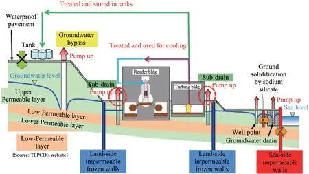
Figure 11 Measures introduced at Fukushima Daiichinuclear power station and artificially frozen ground wall(https://www4.tepco.co.jp/en/decommision/planaction/landwardwall/index‐e.html;https://www.meti.go.jp/english/earthquake/nuclear/decommissioning/pdf/20190814_current_status.pdf)
5 Conclusions
Engineering technology related to frozen soil and frost heaving has developed related to the design,con‐struction,and maintenance of LNG in‐ground storage tanks and artificial ground freezing over the last half‐century in Japan.This development is supported by the basic empirical frost heaving research effort,and by the practical effort to verify prediction results and field observation results of the stress‐strain behav‐ior of freezing ground.Furthermore,the high quality of frozen ground engineering required in crowded cities like Tokyo has accelerated improvements in its reliability and prediction accuracy.
Another important point regarding the improve‐ment of frozen ground engineering in Japan is the standardization of(1)frost heaving tests and(2)the procedure of how to use the test results.This effort has improved the universality of frozen ground engi‐neering.Of course,these improvements are based on the pioneering scientific work conducted for over a century.
Acknowledgments:
The author is grateful to SCAR for giving me an op‐portunity to submit this article and also to Prof.Mar‐garet M.Darrow of UAF for her useful advice during the preparation of this article.
 Sciences in Cold and Arid Regions2021年2期
- Sciences in Cold and Arid Regions的其它文章
- Guest Editors Fujun Niu and Jiankun Liu for special Issue International Conference on Permafrost
- Frost susceptibility of soils―A confusing concept that can misguide geotechnical design in cold regions
- Laboratory study and predictive modeling for thaw subsidence in deep permafrost
- Permafrost distribution and temperature in the Elkon Horst,Russia
- Afull-scalefield experiment to study thethermal-deformation process of widening highway embankmentsin permafrost regions
- Sandstone-concrete interface transition zone(ITZ)damage and debonding micromechanisms under freeze-thaw