A Wideband E-Plane Crossover Coupler for Terahertz Applications
Xiaohe Cheng,Zhiyan Liu,Yuan Yao*,Junsheng Yu,Xiaodong Chen
1 Beijing Key Laboratory of Work Safety Intelligent Monitoring,School of Electronic Engineering,Beijing University of Posts and Telecommunications,Beijing 100876,China
2 School of Electronic Engineering and Computer Science,Queen Mary University of London,London E1 4NS,U.K.
Abstract:In this paper,a new approach to design terahertz(THz)E-plane crossover coupler is reported.By cascading two symmetrical septum polarizers,a simple structure with wide operating bandwidth and high isolation performance is achieved.The working principle is explained by operating waveguide modes.To simplify the optimization process,the scattering matrix(S-matrix)of the crossover is calculated.Two prototypes loaded and unloaded electromagnetic band gap(EBG)are fabricated and measured.The electrical contact problem at assembly plane is eliminated by the prototype loaded EBG.A measured bandwidth of 17.3%from 92.5 to 110 GHz for reflection and isolation coefficients<-15 dB and transmission coefficient>-2 dB is achieved.
Keywords:butler matrix;crossover coupler;high isolation;multi-beam;THz
I.INTRODUCTION
Terahertz(THz)communication has attracted rapidly growing interest due to its unique spectrum advantages of abundant spectrum resources and moderate beam width and great potential in many applications such as inter-satellite communications[1],mobile communications and ultrafast short-range wireless communications[2,3].One of the main challenges of THz links is the high free space path loss,which must be compensated to hold the reliable signal-to-noise-ratio(SNR)for receiver.Therefore,the high gain antennas are usually required for THz communication system[4].In addition,multi-beam with passive beamforming network can be utilized to improve the spatial coverage with low loss[5].
Butler matrix is the most widely used in multi-beam feeding network,which has compact structure and low insertion loss.Crossover is an important part of Butler matrix and its insertion loss,operating bandwidth and isolation directly affect the whole matrix performance.The conventional microwave crossover implemented by microstrip line has advantages of low cost,compact structure and easy for integration[6].However,the microstrip line suffers from large radiation loss and dielectric loss at THz band[7].For THz component design,the TE mode transmission lines can effectively avoid the radiation loss and thus achieve the lower insertion loss.
There are many ways to build the crossover based on TE mode transmission line,such as by concatenating two 3-dB 90° hybrid coupler[8-11],by introducing metallic vias at the junction of waveguide[12],by inserting dielectric plates into the waveguide junction[13],or by creating short slot between the adjacent ports[14,15].However,most of these designs still suffer from low isolation or narrow bandwidth.In[10],a gap waveguide crossover consisting of two 3-dB 90° hybrids has been design.The two sides pins of gap waveguide has been slightly optimized to minimize the coupling.However,the 15-dB isolation bandwidth is only 6.4%.In[13],a partially dielectric filled hollow waveguide in-plane crossover is proposed.Compared with the via-based in-plane crossover,its bandwidth is enhanced but still less than 8%.In addition,most of the reported works are focus onH-plane and In-plane crossover,theE-plane type is seldom reported.TheE-plane crossover is the key component for buildingE-plane or 2D Butler matrix.
To address the aforementioned challenges,in this paper,a novel approach for designing wideband THzE-plane crossover is proposed.The structure is cascaded by two symmetrical septum polarizers.The scattering matrix(S-matrix)of the proposed crossover is calculated and validated by full-wave simulation.Furthermore,to estimate the influence of air gap during the practical assembly process,two crossover prototypes loaded and unloaded with electromagnetic band gap(EBG)structure are fabricated and measured.A measured bandwidth of 17.3% for insertion loss less than 2 dB,isolation coefficients less than-15 dB and reflection coefficient less than-15 dB is achieved in the loaded EBG prototype.
II.CROSSOVER COUPLER DESIGN
2.1 Crossover Configuration
The structure of the crossover coupler is shown in Figure 1,cascaded by symmetrical septum polarizers with distance ofd.The crossover is a component with four ports,where #1 and #4 are served as input and coupled ports,respectively,and#2 and#3 are the isolated ports.The septum polarizer consists of two rectangular waveguides,a square waveguide and a five steps septum located at the center of square waveguide.The thickness of septum and the width of square waveguide are expressed intanda1,respectively,and the dimensions of the crossover are listed in Table 1.The all simulation results of this paper were simulated in HFSS,and the materials of square waveguide and septum are air and aluminum,respectively.

Table 1.The dimensions of the optimized crossover(unit:mm).
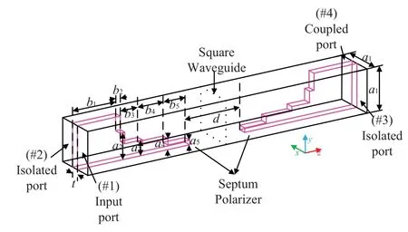
Figure 1.The geometry of Crossover.
2.2 Principle of Operation
Since the crossover is comprised of septum polarizers,its operating principle can be analyzed from the septum polarizer.The septum is a three-ports device,two rectangular waveguide and a square waveguide.As shown in Figure 2,the signal independently excited by Port 1 can be considered as a superposition of the even and odd modes[16,17].For the even and odd modes excitation case,the septum block serves as two boundary condition,the former for the perfect electric wall(PEW)and the latter for the perfect magnetic wall(PMW).Therefore,the TE10and TE10modes can be generated at the square waveguide aperture with these two excitation cases.Furthermore,since the propagation constants for TE10and TE10modes are different,the phase shift of±90°(the sign depends on which rectangular waveguide is excited)of these two orthogonal modes can be achieved.Consequently,the left-hand-circular-polarization(LHCP)and righthand-circular-polarization(RHCP)can be generated at square waveguide by independently exciting Port 1 and Port 2,respectively.
To illustrate the working process of the crossover,the mode distributions at different planes with #1 exciting condition is presented in Figure 3(a).For the left septum polarizer,the TE10mode transfers to a LHCP electromagnetic wave from #1 to the middle square waveguide.The right septum polarizer serves as a receiver,which receives the LHCP wave to #4.The full-wave simulated electric field distribution are presented in Figure 3(b),which also reveals the energy transfers from#1 to#4.Obviously,the bandwidth of crossover is decided by septum polarizer,which relative bandwidth is usually around 25%.By optimizing the septum carefully,the septum polarizer can realize narrow band with high isolation[17]or wide relative bandwidth[18].
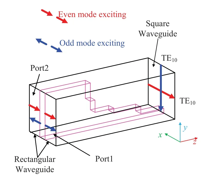
Figure 2.Even and odd modes conversion process of the septum polarizer.
2.3 Optimization Method
In order to simplify the optimization process of crossover,theS-matrix is calculated to establish the relationship between the septum polarizer and the proposed crossover.And thus the reflection coefficient,isolation,and transmission coefficient of whole crossover performance can be equivalent to the specific performance optimization of the septum polarizer.Due to two orthogonal modes can propagate in the square waveguide,the septum polarizer is actually act as a four-port component from the electrical point of view.Furthermore,the two modes are generated by even and odd modes condition.Therefore,theSmatrix of the left septum polarizer for even-and oddmodes can be expressed as[17]:
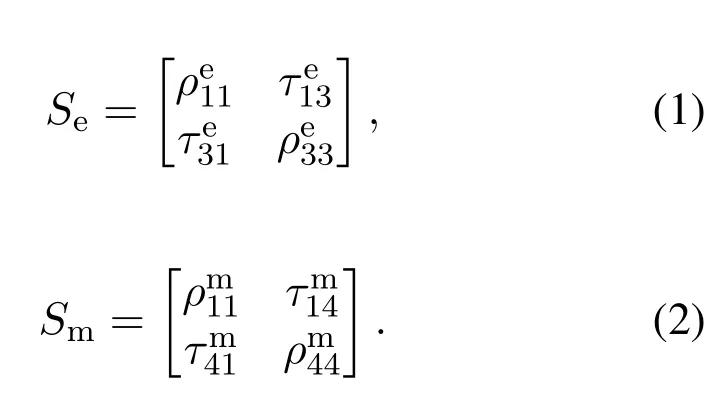
where the superscript e and m represent the even-and odd-modes of the septum polarizer,respectively.And the ports definition is given in Figure 4(a).
Consequently,the four-portS-matrix of the left septum polarizer can be characterized as follows:
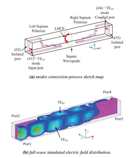
Figure 3.Modes conversion process of the proposed crossover.
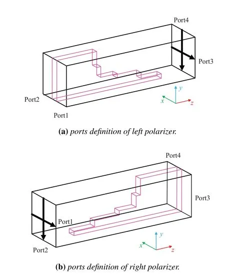
Figure 4.Ports definition of the septum polarizer.
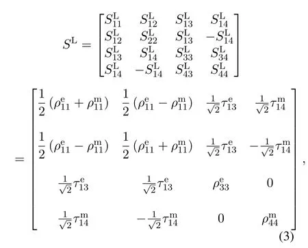
Furthermore,the right septum polarizer scattering matrix ofSRcan be expressed as:

where the ports definition of is shown in Figure 4(b),and the specific values ofSRare equal toSLbecause of the structure symmetry of the left and right polarizer.
Due to the limitation ofS-matrix for cascading multiport networks,the transmission matrix(T-matrix)is employed to calculateS-matrix of crossover,which provide a straightforward method with simple matrix multiplication[19].The conversion between theSandT-matrix for multiport network can be expressed as:
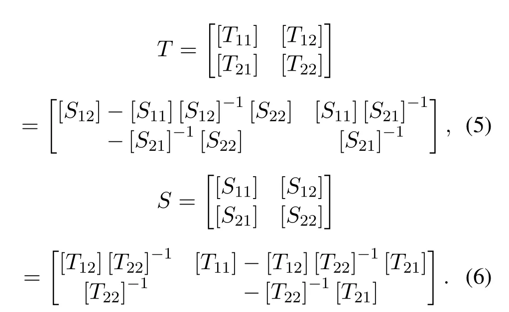
By multiplying theT-matrix of left and right polarizer and then transferring the multiplicationT-matrix toS-matrix,theS-matrixScof whole crossover can be expressed as follow:

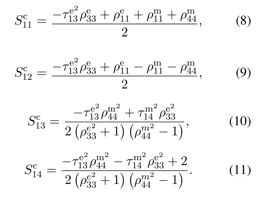
The reflection coefficientand isolationof the crossover are given in(8)an d (9),respectively.and it should be noted that the results ofandare simplifeid.For lossless ideal case,thefrom(3)and+1≈1.Therefore,with lowerand higherthe bettercan be achieved.For isolationand transmmssion coefficientare key parameters to make them close to 0 and 1,respectively.
To verify the calculatedS-matrix of proposed crossover,the full-wave simulation is employed and the comparison results are shown in Figure 5.It should be noted that the dimensions of the crossover are kept same as given in Table 1.From Figure 5(a),the simulated and calculated reflection coefficients of crossover are lower than-20 dB,and insertion loss is better than 0.2 dB within working bandwidth from Figure 5(d).It also can be seen from Figure 5(b)and(c),the isolation of crossover is below-20 dB,respectively.The little difference between calculated and simulated results is caused by the coupling of port3 and port4 in(3),which is ignored in calculation.
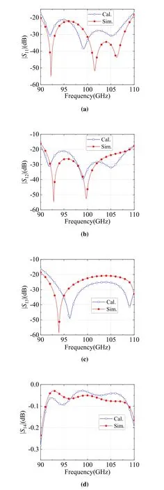
Figure 5.Simulated and calculated S-parameters of the crossover.
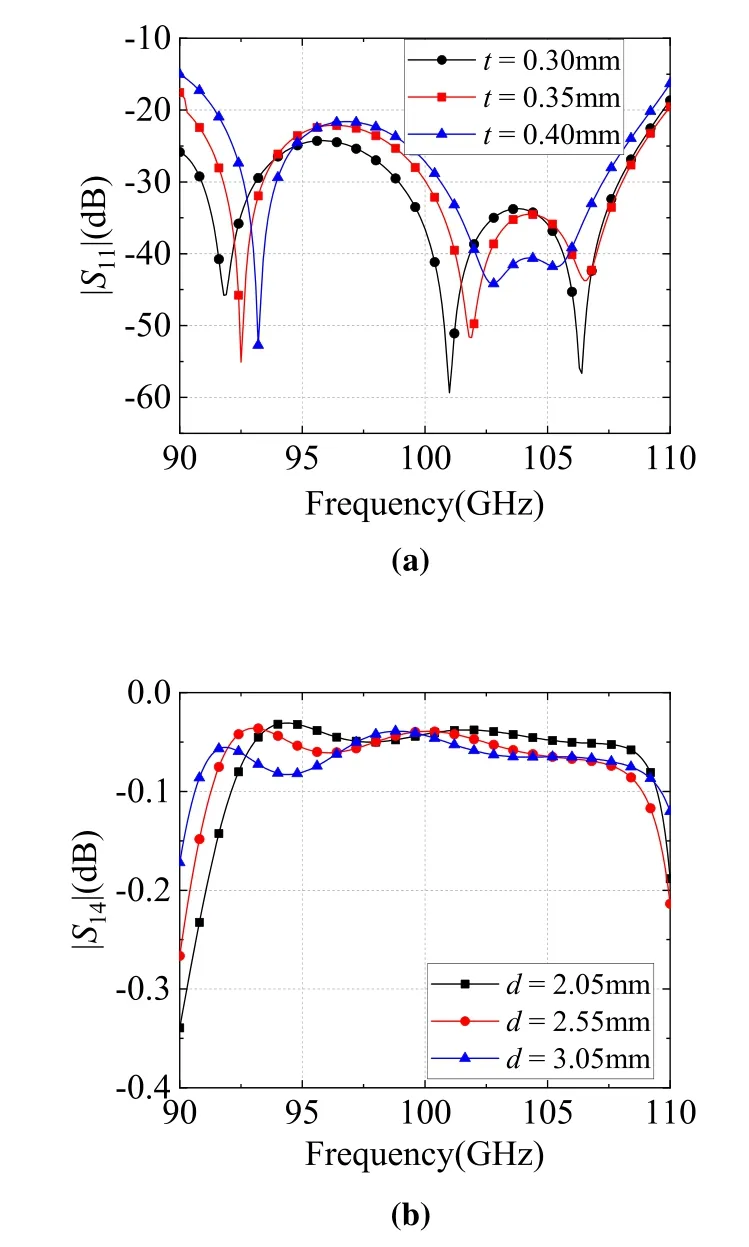
Figure 6.The influence of t and d.
Figure 6 presents the influence oftandd.From Figure 6(a),it can be seen that as the thickness of septum t decreases,the reflection coefficients will be better.However,the processing difficulty will increase as the thicknesstdecreases.As for spacingd,although it has little effect on insertion loss,the length of crossover is influenced byd.In order to facilitate processing and make the structure compact,the values oftanddare 0.35mm and 2.55mm,respectively.
III.FABRICATION
Considering the measurement of the crossover,four waveguide transformers with 90°E-plane bends are used to convert the four ports of the crossover into standard WR-10 rectangular waveguides(2.54 mm×1.27 mm)as shown in Figure 7.In order to achieve good impedance matching,the reflection coefficients of waveguide transformer and 90° E-plane bend are both optimized less than-20 dB,which is presented in Figure 8.And the structure dimensions are summarized in Table 2.
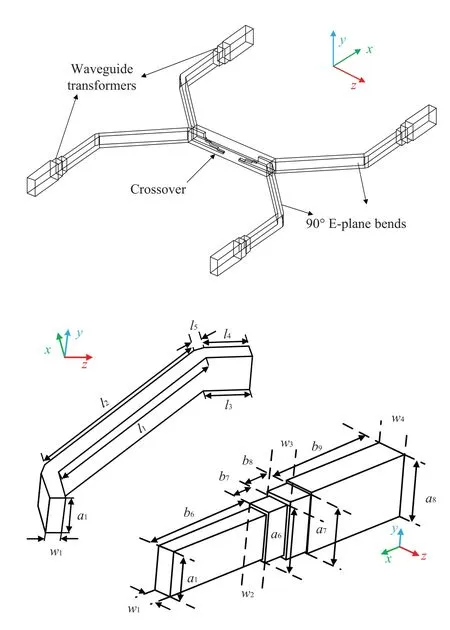
Figure 7.Geometry of waveguide transformer and 90°Eplane bend.
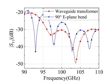
Figure 8.The reflection coefficients of waveguide transformer and 90°E-plane bend.
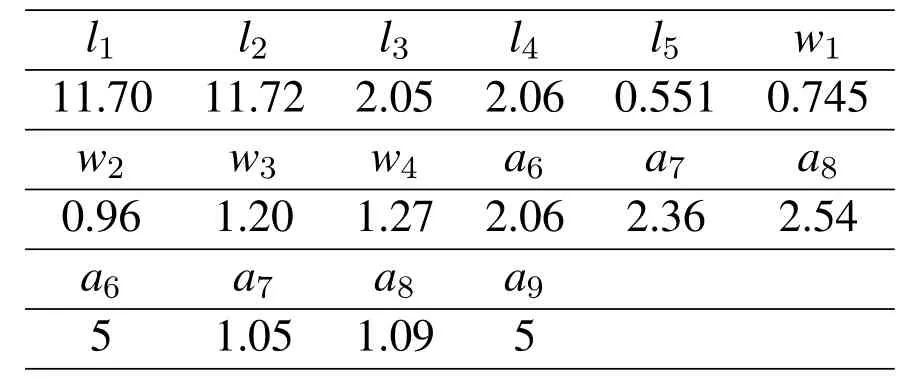
Table 2.The dimensions of the optimized waveguide transformer and 90°E-plane bend(Unit:mm).
For computerized numerical control(CNC)milling technology,the THz components based on hollow waveguide structure usually need to be divided into several blocks and assembled by using fixing screws.The assembled process inevitably introduces the air gap between metal-to-metal contact plane,which would lead to the electrical performance degradation.To evaluate the impact,two crossover prototypes with and without electromagnetic band gap(EBG)are fabricated and the structures are presented in Figure 9.Both of them are split into two along the top of the square waveguide.The EBG structure is kept same as the metal pin of gap waveguide,proposed by Prof.Kildal[20,21],which is an innovative technology to solve the electrical contact problems of standard waveguide transmission line at millimeter-wave or THz band.Thanks to the stopband characteristics of EBG,high air gap can be toleranted in fabrication assembling process.The dispersion diagram of EBG is presented in Figure 10,it can be obversed that as the air gap ofgincreases from 20μm to 40μm,the frequency stopband ranging from 50 to 180 GHz is guaranteed,which covers the operating bandwidth.
For evaluating the influence of EBG,the coupling performance of two prototypes with different air gap values between metal-to-metal contact plane are simulated and the results are shown in Figure 11(a)and(b).It should be noticed that the simulation results didn’t cotain the influence of waveguide transformer and 90°E-plane bend.It can be seen that without the EBG,the insertion loss degenerates from 0.75 dB to 29 dB with the air gap ranging from 0 to 20μm.On the other hand,the influence of air gap has been obviously reduced for the crossover loaded with EBG structure.With the air gap varying from 0 to 20μm,the insertion loss is only deteriorated 3 dB.Therefore,by loading EBG in crossover,the assembly errors tolerance can be enhanced.
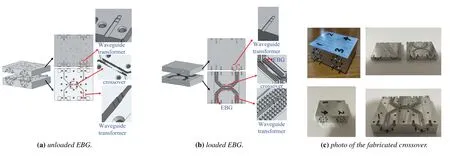
Figure 9.Assembly of the fabricated crossover.

Table 3.Comparison of different crossover.
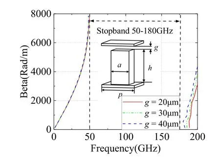
Figure 10.The dispersion diagram of EBG.The dimensions of the EBG unit are a=0.04 mm,p=0.73 mm,h=0.73 mm,g=0.02 mm.
IV.MEASUREMENT AND DISCUSSION
To verify the design,theS-parameters of the two crossover prototypes with and without EBG structures were simulated in HFSS and measured by Ceyear3672D vector network analyzer with two 3643PW-band extenders.And the ports that are not under test are connected to the WR-10 waveguide loads.
4.1 Simulation and Measurement Results of the Crossover Unloaded EBG Structure
The simulated and measuredS-parameters of crossover without EBG structure are showed in Figure 11.The simulated and measured reflection coefficient of|S11|are lower than-10 dB,while the isolations of|S12|and|S13|are all lower than-15 dB.However,the measured transmission coefficient is seriously deteriorated,which is caused by the air gap between the metal-to-metal assembly planes as presented in Figure 11(a).After simulation test,the air gap is about 7μm.
4.2 Simulation and Measurement Results of the Crossover Loaded EBG Structure
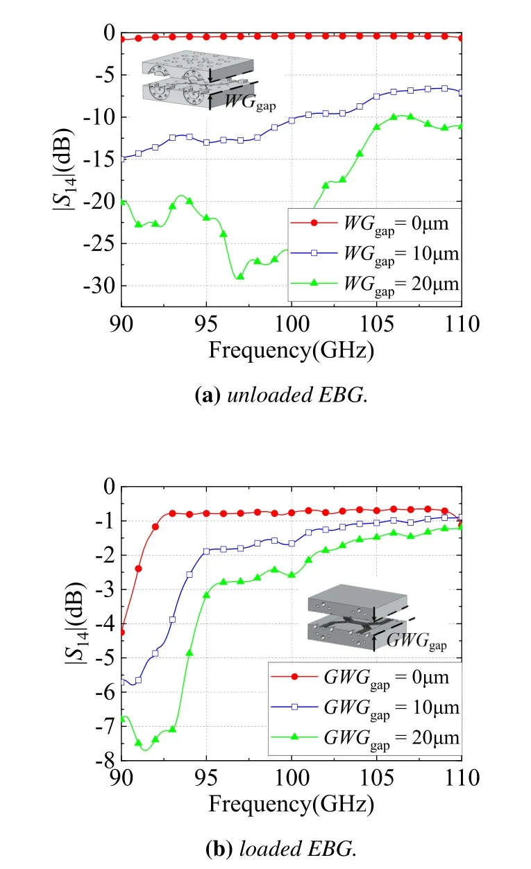
Figure 11.Tolerance analysis of the crossover.
The simulated and measuredS-parameters of crossover with EBG structure are showed in Figure 13.The measured results are agreed well with the simulated results.The simulated and measured reflection and isolation coefficients are all lower than-15 dB from 92.5 GHz to 110 GHz.The simulated and measured transmission coefficients are higher than-1 and-2 dB,respectively.Although crossover with EBG can avoid the effects from air gap,the whole performance of crossover will be influenced by EBG aperiodic placement,such as the junction of crossover and 90° E-plane bend,the 45° E-plane bend,which can be seen in Figure 9(b).Therefore,the crossover with EBG structure should be design carefully.
4.3 Comparison and Discussion
The performances of the crossover with different types are summarized in Table 3.Although crossover bandwidth in[6]up to 53%,the performance of crossover based on microstrip line will deteriorate seriously in THz.Due to the advantage of the lowest loss in all structure,the crossover based on waveguide has potential in high frequency,such as[9,10,13]in Table 3.The crossover in[10]and[13]have higher isolation and lower insertion loss than this work,but wider operating bandwidth of this work will be attractive in high frequency application.Compared with above crossover,the proposed crossover has wider bandwidth and compact structure,better tolerance of manufacturing and assembly errors.
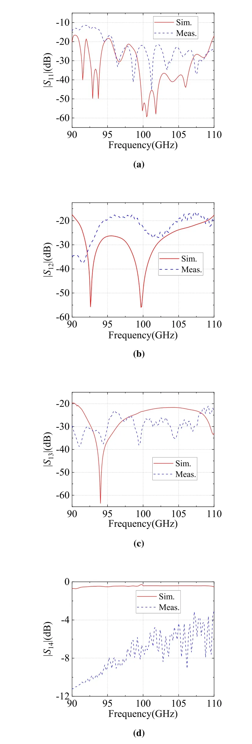
Figure 12.Simulated and measured S-parameters of the proposed crossover without EBG.

Figure 13.Simulated and measured S-parameters of the proposed crossover with EBG.
V.CONCLUSION
A novel THz crossover coupler consisting of two symmetrical septum polarizers has been reported in this paper.The working principle and process of the crossover are explained.The proposed crossover inherits the feature of septum polarizer.Therefore,wide operating bandwidth and high isolation performance are achieved.To estimate the influence of electrical contact problem during assembly process,two crossover prototypes with and without EBG are fabricated and measured.The transmission coefficient is obviously improved by loading the EBG.The experimental results show that 17.3%relative bandwidth ranging from 92.5 GHz to 110 GHz is achieved with return and isolation loss>15 dB and insertion loss<2 dB.Its high isolation and simple structure are suitable to be used inE-plane/2D Butler matrix.By appropriately scaling the size of the proposed structure,this crossover can be applied to higher frequency range.It is a very attractive candidate for THz wireless communications.
VI.ACKNOWLEDGEMENT
This work was supported by the National Natural Science Foundation of China under Grant No.61474112 and Grant No.62001039.
- China Communications的其它文章
- AI Assisted PHY in Future Wireless Systems:Recent Developments and Challenges
- Secrecy-Enhancing Design for Two-Way Energy Harvesting Cooperative Networks with Full-Duplex Relay Jamming
- Adaptive Maxwell’s Equations Derived Optimization and Its Application in Antenna Array Synthesis
- A 16-QAM 45-Gbps 7-m Wireless Link Using InP HEMT LNA and GaAs SBD Mixers at 220-GHz-Band
- Terahertz Direct Modulation Techniques for High-speed Communication Systems
- A Semi-Blind Method to Estimate the I/Q Imbalanc of THz Orthogonal Modulator

