A 16-QAM 45-Gbps 7-m Wireless Link Using InP HEMT LNA and GaAs SBD Mixers at 220-GHz-Band
Yukun Li,Yong Zhang,Chengkai Wu,Jianhan Cui,Huali Zhu,Bo Yan
School of Electronic Science and Engineering,University of Electronic Science and Technology of China,Chengdu 611731,China
Abstract:This paper presents a 220-GHz-band 7-m wireless link with a 45-Gbps transmission data rate by using 16 quadrature amplitude modulation(16-QAM).Super-heterodyne transceiver modules are developed for transmission and reception of the modulated signals,which consist of a Schottky barrier diodes(SBD)based sub-harmonic mixer(SHM),an InP HEMT low noise amplifier(LNA),a waveguide band-pass filter(BPF),and a 108-GHz local oscillator(LO)multiplier chain.The transmitter features a peak transmit power of 1.41 dBm,and the IF frequency varies from 5 GHz to 20 GHz.Besides,the receiver features a conversion gain of 9.3 dB in average and a noise temperature of 3052.8 K.The measured results indicate that the transceiver modules enable data transmission of a 45-Gbps 16-QAM signal with Signal-Noise-Ratio(SNR)from 11.59 dB to 15.36 dB in a 7-m line-of-sight channel.
Keywords:wireless link;16 quadrature amplitude modulation(16-QAM);super-heterodyne transceiver modules;sub-harmonic mixer(SHM)
I.INTRODUCTION
In recent years,wireless capacity is increasing at a prodigious rate,the IP traffic is exploding all over the world in 2018[1,2]and there are more than 11 billion mobile connected devices by the Internet of Things(IoT)paradigm in 2020[3].Obviously,the increasing requirement for wireless capacity brings significant challenge to the existing wireless communication technologies.Although the commercial 5th generation mobile networks(5G)at millimeter-wave frequencies can support data rates of more than 10 Gbps in the future[4],most of applications beyond 10 Gbps still need to depend on optical fiber communication[5].However,optical fiber communication technology is difficult to support application in high-speed mobile scenario.In this background,wireless communication technologies using carrier frequency above 100 GHz(or call it as terahertz communication)will be available to support application with more than 100 Gbps and provide abundant available spectrum[6,7].It is expected that high-speed terahertz wireless link will play a central role in future wireless communication systems for its high capacity and security,and it will become a decisive factor in the competition of science and technology.
Generally,terahertz communication is mainly addressed by photonics technologies[8-12]and active electronics devices[2,13,14].Photonics technologies have been proven a promising solution,which features the capability of generate broadband terahertz signals with frequency tunability and a high transmission speed can be achieved by optical modulation.In[10],this work achieved a 100-Gbps data rates by using photonic sub-harmonic mixer and 16-QAM modulation.Besides,in[12],this work achieved a 612.65-Gbps data rates by using photonic sub-harmonic mixer and 64-QAM OFDM modulation.However,the photonics devices are limited by their own low photoelectrical conversion efficient,and cannot meet the need of long-distance data transmission.On the other hand,with the rapid development of the semiconductor technology such as InP HBT and InP HEMT[15,16],active solid-state electronics technologies shown great advantages on their high output power and high integration especially from 0.1 THz to 1 THz[17].Some representative developments are including a 25-Gbps wireless link operating at 220 GHz in 50-nm mHEMT MMIC technology[13],and a 120-Gbps wireless communication link working at 300GHz in 80-nm HEMT MMIC technology[2].Besides,[14]employed a combination of a photonic and electronic technologies,and this wireless link achieved a data rate of 100-Gbps.Therefore,wireless communication system from 200 GHz to 300 GHz is available to meet the requirement of the wireless capacity beyond 10 Gbps.

Figure 1.Block diagram of the 220-GHz-band wireless link.
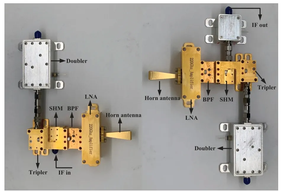
Figure 2.Photograph of transmitter and receiver.
In this paper,a 45-Gbps 16-QAM wireless link working at 220-GHz-band is reported.A superheterodyne front-end is designed for transmission and reception of the modulated signals by using component-based architecture for its great convenience on modifying and packaging.Circuits including LO multiplier,SHM,BPF,and LNA are packaged as waveguide modules.This paper is organized as follows:In Section II,the architecture of wireless link and the performance of each module are described,and the link budget calculation of the proposed transceiver is introduced.The design process and measured results of the critical modules for the proposed transceiver are introduced in Section III.In Section IV,wireless link experiments with 16-QAM modulation are given.Finally,conclusion is drawn in Section V.
II.OVERVIEW OF THE WIRELESS LINK
2.1 Transceiver Architecture
The principle block diagram of wireless link is shown in Figure 1.This wireless link is composed of a transceiver and a signal processing platform,which enables transmission and reception of the modulated signals,the IF signal is range from 5 GHz to 20 GHz.As shown in Figure 2,super-heterodyne frequency mixing architecture is adopted in this transceiver,the modulated IF signal is carried out up or down frequency conversion by using GaAs Schottky barrier diodes(SBDs)based SHM,which is driven by a Wband×6 multiplier chain.This frequency multiplier chain consists of a SBDs based tripler and a doubler amplifier stage.This doubler amplifier stage has a 4.6-W power consumption with a 4-dBm input signal and it provides a 21-dBm driving power after connecting a 4-dB attenuator for the frequency tripler at 36 GHz.Additionally,this tripler reaches an output power of 5 dBm at 108 GHz with a 2.5%conversion efficiency.At the transmitter side,the modulated IF signal from 5 GHz to 20 GHz is up converted by using SHM,the carrier wave range from 221 GHz to 236 GHz is filtered by a rectangular waveguide BPF and then amplified by a LNA module.The measured maximum output power of the transmitter is 1.41 dBm at 226 GHz,as shown in Figure 3.For receiver,the received signal is down converted by using a same architecture before being delivered to the demodulation platform,the carrier wave range from 221 GHz to 236 GHz is first amplified by using a same LNA module,and then is down-converted through a same mixing stage.Besides,a same waveguide BPF is connected between the SHM and LNA.Finally,the carrier wave range from 5 GHz to 20 GHz is finally amplified to by an IF amplifier module.The measured conversion gain of the receiver is 9.3 dB in average within 221 GHz to 236 GHz,as shown in Figure 4,and the calculated noise figure of receiver is 10.8 dB in average within 221 GHz to 236 GHz.
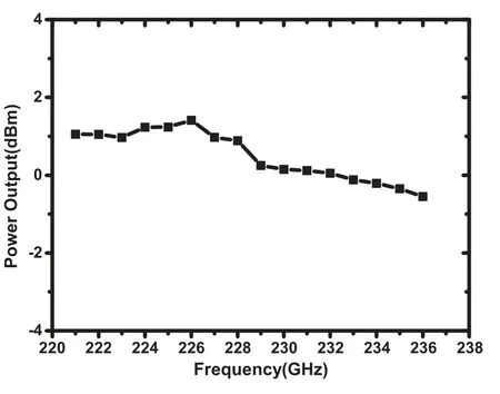
Figure 3.Measured output power of transmitter.
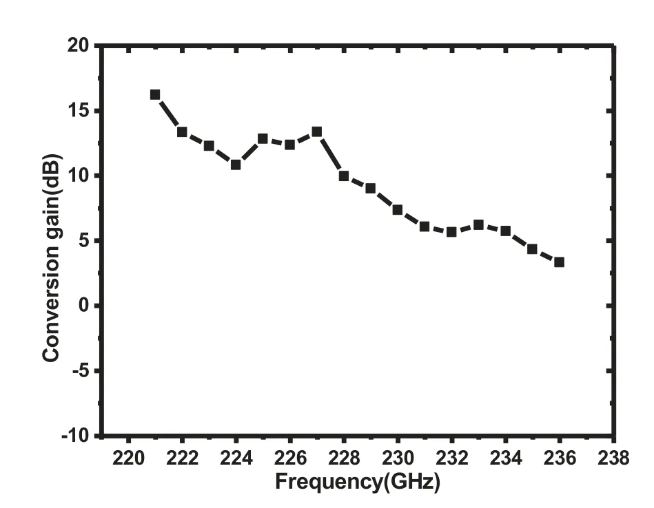
Figure 4.Measured down-conversion gain of receiver.
2.2 Digital Signal Processing(DSP)Routine
The digital signal processing(DSP)routine is shown in Figure 5.At the transmitter side,low density par-ity code combined with OFDM system is employed.At first,the PRBS sequence is translated as LPDC-16-QAM symbols,which has an improved transmission efficiency and coding gain.Then,IFFT is used to translate the the frequency domain symbols to time domain.Next,a normal cyclic prefix(CP)is inserted to reduce the impact on the inter-symbol interference(ISI).At the receiver side,the received signal is converted as IF signal.Then,IFFT is used to realize OFDM demodulation after CP is removed.Then,the user data is recoverd back by 16-QAM de-maping and LDPC de-coding.
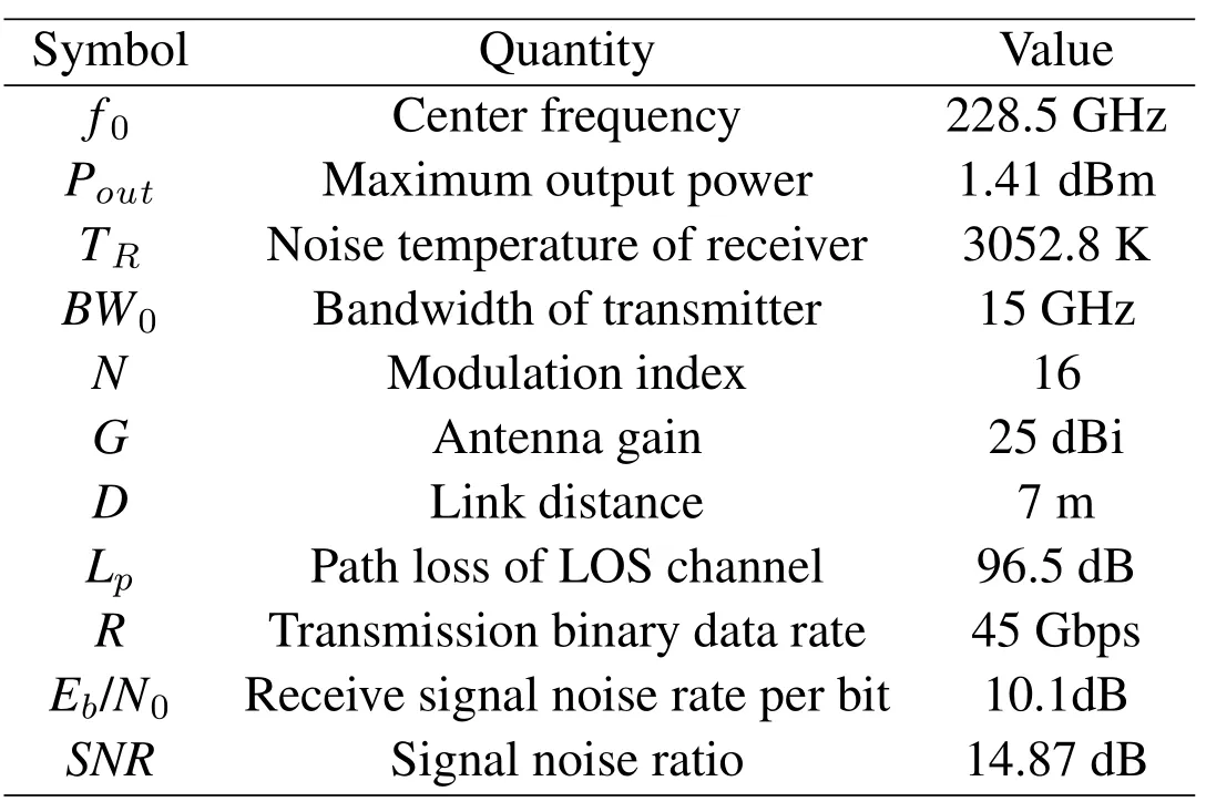
Table 1.The performance of the wireless link.
2.3 Link Budget
In order to build up an available short-range wireless link by using the proposed tranceiver,WR-3 horn antennas with a gain of 25 dBi are connected in front of the terahertz front-end.Then the link budget analysis of the proposed front-end is characterized by Signal-Noise-Ratio(SNR),which can be calculated by

WhereSandNrepresent the average power of the output signal and noise,Eb/N0isSNRper bit,RbandWare the transmitting bit rates per second and the signal bandwidth,respectively.Our assumption is a 45-Gbps 16-QAM signal in 15-GHz bandwidth,and the centered frequency is 228.5 GHz.In this calculation,the maximum link distance can be calculated while the requiredSNRis 15 dB.First,the maximum link distance(D)can be defined by the maximum loss of the lightof-sight(LOS)channel as follows:

Figure 5.The DSP routine of(a)transmitter,(b)receiver.

Wherecrepresents the speed of the light,and the center frequency(f0)is 228.5 GHz.Then,the maximum loss of the light-of-sight(LOS)channel is calculated by:

WherePRandPTare the received power and the transmit power,GTandGRare gain of horn antennas in front of the front-end,LArepresents additional loss of wireless link and antenna misalignment,which is about 1 dB in both the transmitter and receiver.Besides,in order to accurately analysis the channel performance range from 200 to 300 GHz,the effects of fog and rain attenuation should be taken into account[18-21],the atmospheric attenuation(L0)under clean sky and heavy rain is characterized as 3dB/Km and 23dB/Km[13],respectively.The received power(PR)can be calculated through(4)and(5)as follows:

Wherekis the Boltzmann constant(1.38×10²³ J/K),and the noise temperature(TR)of the receiver can be calculated by

WhereTLN AandTmixerrepresent the noise temperature of LNA and SHM.The noise temperature introduced by LNA and SHM are 2958 K and 950 K by using Y-factor measured method,and the calculatedTRis 3052.8 K.As shown in Table 1,this transceiver can support 45 Gbps signal(16QAM,15 Gbaud)with a maximum loss of the light-of-sight(LOS)channel of 96.5 dB.This means that the calculated maximum link distance of is 7 m(SNR=14.87 dB).
III.CRITICAL CIRCUITS DESIGN FOR WIRELESS LINK
3.1 GaAs SBD Based SHM
In this wireless link,SHM plays an important role in the super-heterodyne transceiver for signal generator and detector.A sub-harmonic mixing structure is employed for mixer design,which can sharply reduce the requirement of high frequency LO signal.This SHM is designed by using anti-parallel GaAs Schottky barrier diodes(SBDs),and passive linear parasitic parameters are extracted by using 3D full-wave electromagnetic simulation after considering all of the layers and materials of the SBDs,as shown in Figure 6(a).Combined with an intrinsic nonlinear SPICE model,a complete SBD model is developed[22],where the junction capacitance(Cj0),series resistance(Rs),reverse breakdown voltage(Vj)and reverse saturation current(Is)are 1.42 fF,12 ohms,0.6 V and 1.75 fA,as shown in Figure 6(b).This sub-harmonic mixer is designed in microstrip environment on 50-um quartz substrate,both of the LO signal and received RF signal are coupled to the substrate by using an E-plane probe transition,as shown in Figure 7(a).Figure 7(b)shows the measured conversion loss of the SHM.When LO frequency is fixed at 108 GHz with power 5 dBm,the measured average conversion loss is 8.1 dB from 198 GHz to 236 GHz.Besides,by using the Y factor method,the measured noise temperature of the SHM is 950 K in average from 221 GHz to 236 GHz.
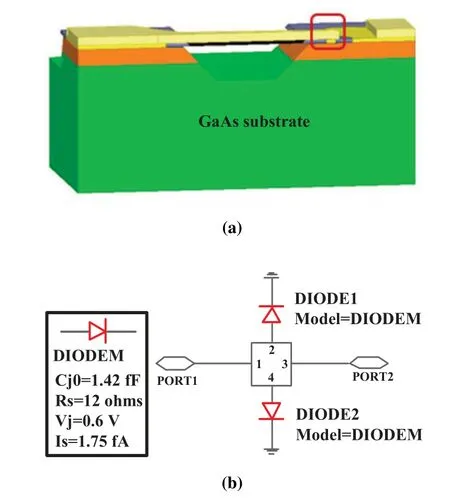
Figure 6.(a)The 3-D electromagnetic model of planar GaAs SBD(b)The SPICE model of planar GaAs SBD.
3.2 220 GHz BPF
A 220-GHz waveguide band-pass filter is designed for frequency election in transceiver.The standardized waveguide WR-4 BPF is designed by using Chebyshev filter matrix synthesize technique,and the structure of nine-pole rectangular resonant cavities is employed.Besides,ultra-sophisticated machining technique with 5-um precision is employed in order to reduce the fabrication tolerance.As shown in Figure 8,the measured center frequency is 220 GHz with a 40-GHz 3-dB bandwidth,and the minimum loss is 0.38 dB at 220 GHz.Besides,the return loss and sideband rejection is respectively better than 20 dB and 40 dB.
3.3 220 GHz InP HEMT LNA
A low noise amplifier in InP HEMT technology is designed for signal amplification in the transmitter and receiver,and it adopts a four-stage common-source configuration,as shown in Figure 9(a).The matching network is designed for minimum noise matching and circuit stabilization in the first stage,while the next three stages focus on high gain and taking into account the noise.Finally,the LNA MMIC is packaged as a module,both the input and output RF signal are coupled to the main substrate by using an E-plane probe,and gold wire bonding is employed to connect to LNA MMIC.DC power supply circuit has been embedded in the module.The measured results show that this LNA MMIC get a gain of about 12.9 dB in average from 221 GHz to 236 GHz,as shown in Figure 9(b).Besides,the measured noise temperature by the Y factor method is 2958 K in average from 221 GHz to 236 GHz.
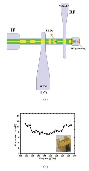
Figure 7.(a)The GaAs SBD SHM(b)Measured conversion loss of SHM.
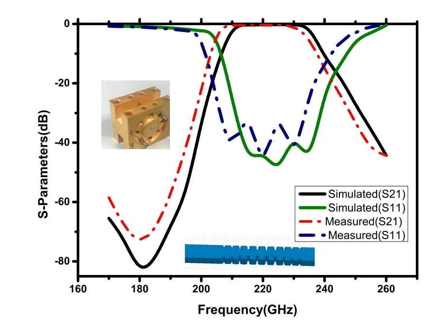
Figure 8.220 GHz rectangular waveguide BPF and measured S-parameter.
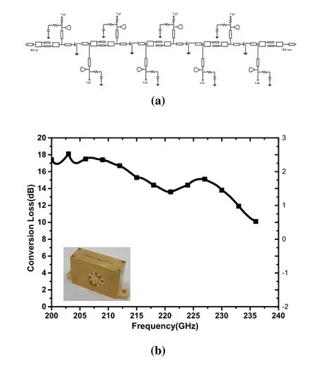
Figure 9.(a)The schematic of 4-stage InP HEMT LNA,(b)Measured small-signal gain of LNA.
IV.WIRELESS DATA TRANSMISSION EXPERIMENTS
The transmitter and receiver modules are placed in a 7-m setup for short-range wireless data transmission experiment,as shown in Figure 10.The measurement is carried out in room temperature.The data transmission test is carried out with a 45-Gbps data rate and 16-QAM format.To generate a wideband 16-QAM IF signal,a Keysight arbitrary waveform generator(AWG)at 80 GSps is used.A Keysight digital storage oscilloscope(DSO)is used as the receiver of the IF signal.The measured results show that the demodulated signals are divided as 7 sub-bands from 3.4 GHz to 14.7 GHz,and the bandwidth of subband is characterized as 1.62 GHz.The corresponding constellations are shown in Figure 11,and the calculatedSNRvalues from the constellations are 11.85 dB,12.28 dB,11.59 dB,12.43 dB,15.36 dB,11.70 dB,and 11.64 dB,respectively.The corresponding calculatedEVMvalues are 25.55%,24.32%,26.33%,23.90%,17.06%,26.01%,and 26.18%,respectively.A 3.98 bit/s/Hz spectrum efficiency has been realized in our 220-GHz-band wireless link,and Table 2 gives a comparison with previous published terahertz wireless links at 220-GHz-band.Besides,a cascaded MMIC power amplifier with higher output power will help us to achieve higherSNRin the future.
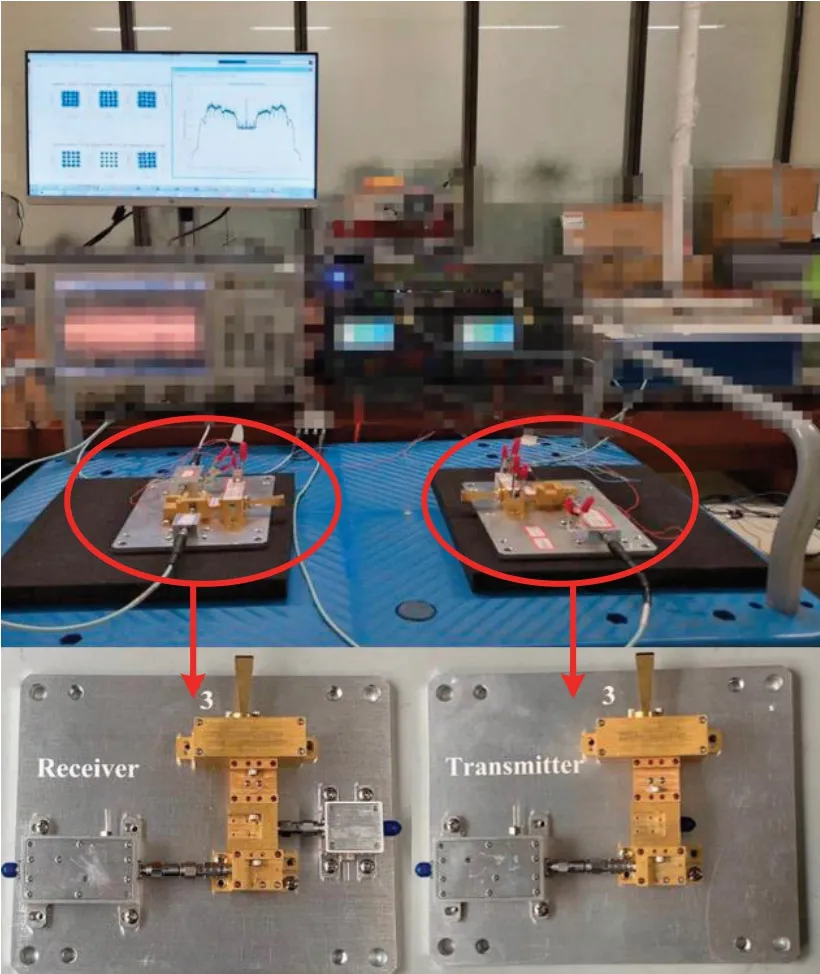
Figure 10.Photograph of 220-GHz wireless link.
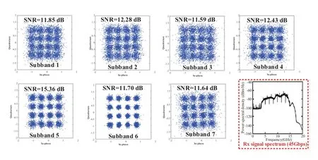
Figure 11.Measured constellation of 16-QAM 45-Gbit/s signal after 7-m transmission in at 220-GHz-band.
V.CONCLUSION
This paper reports a 220-GHz-band wireless link over distances up to 7 m.This link is employed a superheterodyne front-end and a 16 quadrature amplitude modulation.The transceiver is consisted of SHM,LNA,LO multiplier chain,BPF and horn antennas.The feasibility of 45-Gbps wireless transmis-sion was also experimentally verified,and the developed wireless link has successfully demonstrated 16-QAM transmission with a data rate of 45 Gbps in an 11.3-GHz bandwidth.Besides,its spectrum efficiency achieves 3.98 bit/s/Hz,which is better than that of most current links.Finally,this research would lay a foundation for the future analysis of 6th generation(6G)wireless communication.

Table 2.Comparison of the wireless link around 220 GHz.
ACKNOWLEDGEMENT
This work was supported by National Natural Science Foundation of China(No.61871072).
- China Communications的其它文章
- AI Assisted PHY in Future Wireless Systems:Recent Developments and Challenges
- Secrecy-Enhancing Design for Two-Way Energy Harvesting Cooperative Networks with Full-Duplex Relay Jamming
- Adaptive Maxwell’s Equations Derived Optimization and Its Application in Antenna Array Synthesis
- A Wideband E-Plane Crossover Coupler for Terahertz Applications
- Terahertz Direct Modulation Techniques for High-speed Communication Systems
- A Semi-Blind Method to Estimate the I/Q Imbalanc of THz Orthogonal Modulator

