A Semi-Blind Method to Estimate the I/Q Imbalanc of THz Orthogonal Modulator
Juan Liu,Ge Liu,Qiuyu Wu,Ying Wang,He Yue,Changxing Lin,*,Xianjin Deng
1 Microsystem and Terahertz Research Center,China Academy of Engineering Physics(CAEP),Chengdu 610200,China
2 Institute of Electronic Engineering,China Academy of Engineering Physics(CAEP),Mianyang 621900,China
Abstract:In terahertz communication,the direct frequency conversion structure in which orthogonal mixer is the main frequency conversion unit,makes engineers get into trouble of in-phase(I)branch and quadrature(Q)branch imbalance,carrier wave leakage,etc.These damages result in system performance tremendous degrades.We proposed a semiblind method to estimate the I/Q imbalance of THz orthogonal modulator,based on predefined preamble and pilot symbols for quadrature amplitude modulation(QAM).In this paper,a transmitter with Y band quadrature mixer and 20Gbps base-band signal has been tested.The bandwidth of the baseband signal was 7GHz,and the modulation type was 16QAM.By this method,7dB improvement of the system’s symbol Mean Square Error(MSE)has been got.That means the proposed method can be used to eliminate the I/Q imbalance effectively.
Keywords:terahertz communication;quadrature modulator;I/Q imbalance correction;digital signal processing
I.INTRODUCTION
People have been great interested in Terahertz band for future high-speed wireless communication due to its broadband characteristics.To realizing terahertz communication,there are two options,the one is photo electronic implement,and the other is all electronic.For all electronic implement,around the 100Gbps transmission rate of single carrier has been realized[1,2].The main obstacle of increasing transmission rate is the lack of some main blocks,such as Digital-to-Analog Converter(DAC)and Analog-to-Digital Converter(ADC)with high sample rate and high precision.To reduce the requirement for sample rate and precision of DAC/ADC and to improve spectrum efficiency,frequency multiplexing or carrier aggregation is viable but leading to high power consumption and complexity of system.Another method is using direct frequency conversion structure which has significant advantages in power consumption and low requirement of DAC/ADC.Different from the superheterodyne transceiver,the direct frequency conversion structure uses orthogonal mixers instead of ordinary mixers.But every substance has two sides.The direct frequency conversion structure will induce I/Q imbalance,which will degrade the signal quality a lot,especially in terahertz band.For example,in a direct frequency conversion transmitter,there are two baseband branches(I and Q).The performance of filters,DACs will be different.The coupler in the orthogonal mixer will be not ideal.The negative effects of transmitter I/Q imbalance are shown in two aspects[3].Firstly,I/Q imbalance will cause the mirror frequency interference in the band.Secondly,I/Q imbalance will affect the performance of the linearized circuit of the power amplifier.When the frequency band width reaches more than 100 MHz,I/Q imbalance is difficult to be completely eliminated from the perspective of circuit design[4],so it is very necessary to eliminate the impact of I/Q imbalance in the digital domain.
Normally,the I/Q imbalance model can be classified into frequency-independent(FI)and frequency dependent(FD)models.The FI model is mainly induced by the non-ideal local oscillator(LO)and the stable power attenuation between I and Q branches.This model has a stable imbalance value,and only FI I/Q imbalance need to be considered.In comparison,the FD model considers FD I/Q imbalance and FI I/Q imbalance.FD imbalance varies over the bandwidth and is caused by unbalanced frequency responses of the I and Q branches[5].
For traditional millimeter-wave I/Q mixer,less than 50GHz,FI part plays a major role in the I/Q imbalance,and the FD part plays a minor role.The FD imbalance will be noticed only when the higher QAM modulation used,at least 64QAM.Y-band I/Q mixer,unlike traditional millimeter-wave I/Q mixer,is sub-harmonic mixer.The imbalance of sub-harmonic mixer is quite different,in which FD and FI are on a par,and the FI part can’t be evaluated.For example,in the range of whole baseband bandwidth,the measured amplitude imbalance between I and Q channels of second-harmonic mixing was from-0.5 dB to+0.5 dB,and the measured phase imbalance was from-8°to+8°,such as in a W band specimen mixer[6].That means the measured I/Q imbalance value can’t be used to deduce I/Q imbalance pre-compensation coefficient directly.For this embarrassment,an estimation method must be used to work for the realizing of I/Q imbalance digital pre-compensation.
Referring to the estimation method used for tradition millimeter-wave I/Q mixer,there are two directions to do.The one is online,and the other is offline.While no matter online or offline,a down conversion analog circuit is needed,unlike lower millimeter wave(lower than 10GHz).Because in terahertz system,there is no such high sample rate ADC.At present,the maximum sample rate is just few tens GSps,which is far from enough.
If online compensation is wanted,symbol rate and precision of ADC must be considered.For terahertz communication,Gbps throughput makes bandwidth of signal at rang of GHz.In our system,the RF bandwidth is 7GHz.Two 10Gbps ADC are need for direction down conversion,or an ADC with sample rate tens GSps is need for intermediate frequency receiver(less than 10GHz),based on Nyquist Sampling Theorem.Even though there are many ways to reduce the requirement of ADC,a lot has to be done in other ways[7].It’s not cost-effective in the case of 7GHz bandwidth and 16QAM.Especially in high-speed modulation by parallelism,a 20Gbps modulation with main function blocks(including Mapping,Shaping Filter,IQ Imbalance Compensation,etc.)almost cost 70%source of FPGA(Xilinx Kintex UltraScale XCKU-115 FPGA),It’s not worth to add another XCKU-115 FPGA to do online estimate IQ imbalance.Therefor offline is more economic use for 16QAM.
For offline mode,the one is to use all predefined symbols(set as X)based on least square algorithm[8],in which the matrix operation on the predefined symbols and the receiving symbols(set as Y)is needed.The longer the sequence is,the more accurate the estimate works.However,it is difficult to find a given sequence long enough,and the matrix operations will be difficult if the sequence is too long.What’s more,it’s not easy to separate different damage cause by different block in feedback circuit in this way.The other method is to use offline iteration algorithm like online method[9].In the transmitter,the baseband data(X),which must be random,is the input of the orthogonal harmonic mixer,the output of mixer is a Y-band signal.This signal can be down conversed to low intermediate frequency or baseband,after feedback circuit.The received data(set as Y)is sampled by instrument with high-speed ADC.The IQ imbalance can be estimated by using X and Y.While because of the system’s memory effects,all samples should be continuous before the parameter’s iteration converges.Normally,hundreds of thousands of continuous symbols are needed,that means millions of over-sampled sampling points are needed,it’s a big challenge for the CPU of laboratory instrument,except for doing some processing to make both X and Y continuous at any time.It’s hard to realize.If there is any break off,the parameter’s iteration will be affected by the out of alignment.If data source is treated as unknown,the judgement of iteration’s hard slicer is blind.The length of misjudgment of hard slicer depends on the memory effect,it’s uncertain.And if there are some frequency offset between transmitter and feedback circuit,this method doesn’t work.If data source is treated as known,the judgement of iteration’s hard slicer is not blind,which is most accurate when X and Y are aligned correctly,while is totally wrong when they are out of aligned,unless they are realigned again.But every test is random and sudden,we can’t preset the time of realignment.
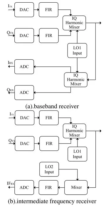
Figure 1.System diagram of THz transmitter with a feedback circuit.
To solve this problem,and to make the estimation simple,a semi-blind estimation method based on predefined preamble and pilot was proposed,which was combined with these two methods mentioned before.In this method,only short predefined sequence(around 100 symbols)is added at fixed intervals in the random unknown data source.And aided by highspeed signal acquisition equipment,simple feedback circuit with one traditional mixer is designed,which will not introduce another IQ imbalance caused by orthogonal mixer.By using predefined preamble,the estimation system is synchronous at all time,even there are some data not continuous,the estimation system will be synchronous again at next preamble,and the pilot is designed for frequency offset.In addition to preambles and pilots,all the other symbols are simply treated as blind.
By the method proposed in this paper,the I/Q imbalance damage of the Y band orthogonal modulator was evaluated.The experimental results showed that 7dB improvement of the system’s symbol Mean Square Error(MSE)has been got,which enabled the communication rate reach 20Gbps.
II.THE I/Q IMBALANCE OF THE TRANSMITTER
2.1 System Diagram
Usually,the main block of an orthogonal modulation transmitter is the I/Q mixer.It makes the baseband signal up-conversion directly to the frequency expected.For terahertz band,the harmonic part is used to realize mixing.The system diagram of our transmitter with an I/Q imbalance correction shows in Figure 2.There are three sources of I/Q balance,the one is phase deviation due to non-ideal phase processing of the coupler in I/Q mixer,the other is different frequency response of baseband filters,DACs and so on,the third is leakage.
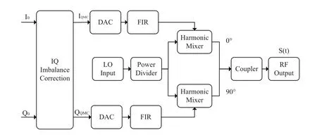
Figure 2.System diagram of THz transmitter with a I/Q imbalance correction.
Figure 3 shows the measured phase and amplitude imbalance of one of I/Q harmonic mixer samples which might be used in the transmitter.From the test results we can see,the fluctuation of imbalance is too large to find an ideal parameter for our compensation in the whole bandwidth.
2.2 I/Q Imbalance Model
Supposing thatI0,Q0are in-phase and Quadrature part of the original signal respectively,αis the amplitude imbalance,θis the phase imbalance,dci/dcq are the leakages of in-phase branch and quadrature branch respectively.
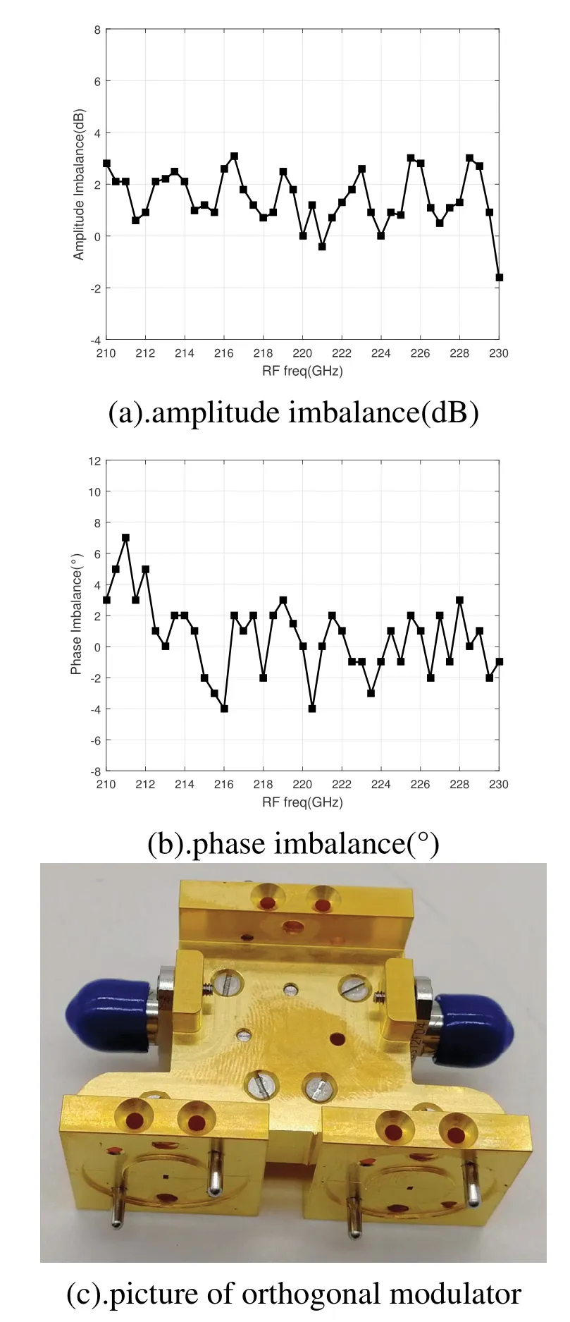
Figure 3.The phase and amplitude imblance of I/Q Harmonic Mixer.
Firstly,taking no account of leakage,the output signals(t),in time domain at radio frequency(RF),can be described as below:

When after ideal demodulation,the received baseband signal(Irx/Qrx)with I/Q imbalance caused by transmitter can be like this:
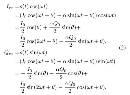
Then discarding the 2ωtdepartment,Irx/Qrxwill be:

Adding the leakage damage,the I/Q imbalance model will be:

2.3 I/Q Imbalance Compensate Model
According to(4),the compensate model can be like(5).
Based on Least Mean Square(LMS)algorithm,the parametric iteration formula can be got like(6),whereerrianderrqare respectively the in-phase and Quadrature part of the error between original signal and received signal.μis the accumulate factor in the iteration.
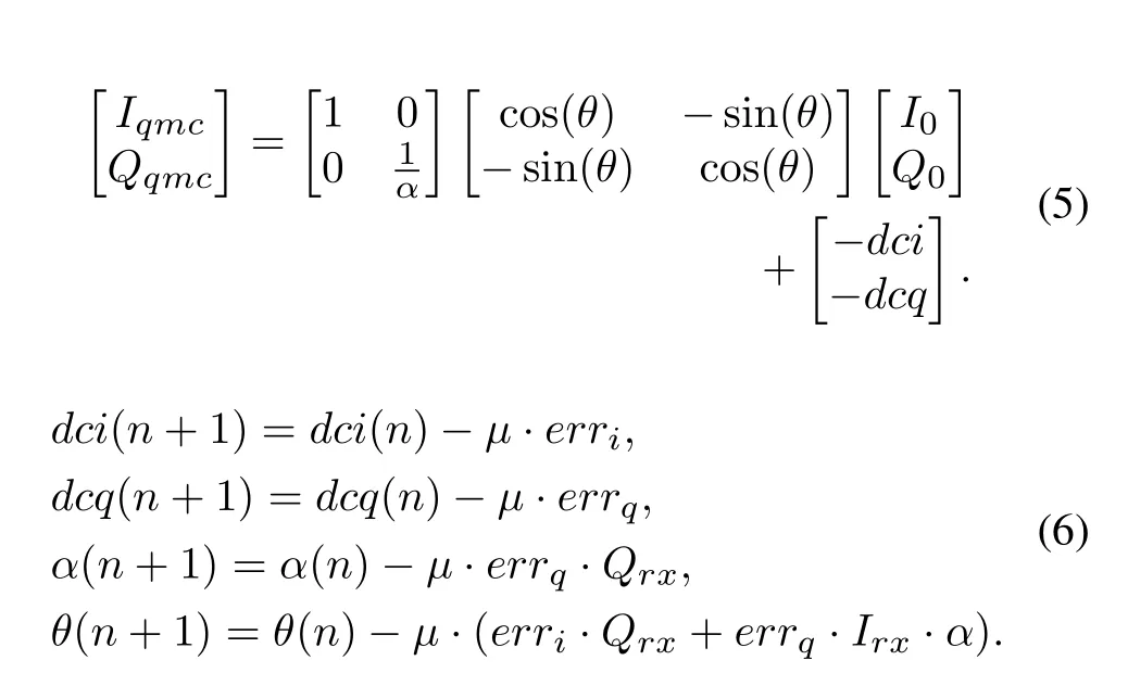

Figure 4.The frame structure of data source.
III.THE METHOD OF ESTIMATION
Form the I/Q imbalance model and compensate model,we can see that it is easy to get the coefficients of I/Q imbalance compensate when the error between original signal and received baseband signal was got.While,things are not as simple as we think.The original signal is not always known.The receiving side is not ideal and some unwanted damage is always involved.To solve these two questions,special digital sources,RF link and preprocessing structure were designed.
First of all,the data source adopts the framing mode with random signal,preamble and pilot sequence.Random data of arbitrary length is inserted into known sequences in a specific format,so that data source of sufficient length can be obtained for loss estimation.The frame structure is shown in Figure 4.This kind of data source is designed to avoid the difficulty of finding excessively long known sequences.
In receiving RF part,a mixer worked on 226GHz is introduced to down converse 220GHz Terahertz signal to low intermediate frequency signal,and then the collected data is used for damage estimation.The addition of direct 226GHz mixer only introduces the carrier frequency offset between two the oscillators and the damage of in-band unevenness,which is linear and can be eliminated by the preamble and pilot sequence.
1.Considering the order of all loss and the characteristic of predefined data source,some digital signal processing was needed before getting the error of I/Q imbalance,shown in Figure 5;
2.Digital Down-Conversion(DDC):down converse the signal to the baseband;
3.Automatic Gain Control(AGC):make the signal power normalized;
4.Timing:do symbol synchronization by interpolation filter based on Farrow structure and timing error based on method of Garnder[10];
5.Maching filter:the root raised cosine filter(RRC),the rolloff factor is set to 0.4;
6.Frame Synchronization(Frame Sync):find frame head and pilot place based on correlation algorithm;
7.Equalizer:use LMS algorithm and get error based on known sequence and hard slicer;the tap of feedforward filter is 48 taps,the accumulate factor is 0.001;
8.Carrier Recovery(CR):use LMS algorithm and get error based on known sequence and hard slicer;the accumulate factor is 0.001;
9.Hard Slicer(HS):symbol level judgment based on Standard constellation point to get the error of random data in the frame structure.
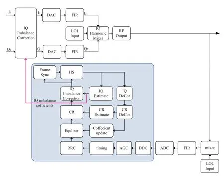
Figure 5.Diagram of I/Q imbalance estimation.
IV.EXPERIMENT AND RESULT
4.1 Experimental Setup
As shown in the Figure 5,the random symbol source of the experiment is generated by MATLAB,which is processed 16QAM mapping,shaping filter(twice up-sample,roll-off factor:0.4),adding 128 special sequence each 2000 symbols,step by step.
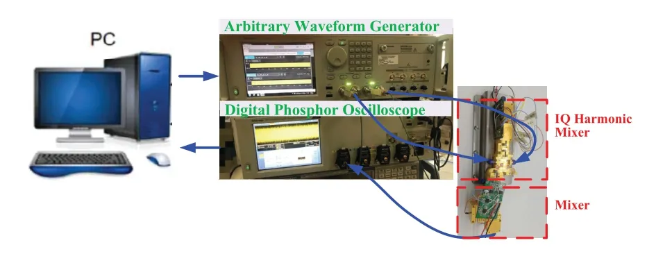
Figure 6.Block diagram for experimental setsup.
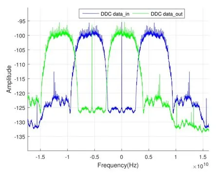
Figure 7.Block diagram for experimental setsup.
The preprocessed data is sent into I/Q harmonic mixer by arbitrary waveform generator,and the clock is set as 10GHz.
The LO of I/Q harmonic mixer is set as 18.333GHz,while the LO of mixer is set as 18.84GHz.
After RF department,a wideband signal(BW=7GHz,CF=8GHz)is received by Digital Phosphor Oscilloscope.The sample rate is set as 50GSps,the record length is set as 1e8.
The received data is processed by MATLAB to get the I/Q imbalance of the I/Q harmonic mixer.The whole experimental setup is shown in Figure 6.
4.2 Results
In the way of digital signal processing shown in Figure 5,we can easily get I/Q imbalance of I/Q harmonic mixer,which can be used as the parameter of I/Q Imbalance Compensation Block directly.
Figure 7 shows the spectrum of the signal before and after digital down-conversion(DDC),where the blue line is the received data after RF link,and the green line is the baseband data after DDC.

Figure 8.Experimental results.
Figure 8(a)(b)shows the constellation of the signal before and after I/Q imbalance compensation.Converting into system’s symbol Mean Square Error(MSE),there was 7dB improvement when I/Q imbalance compensation opened,from-14dB to-21dB,shown in Figure 8(c).Figure 8(d)shows the convergence condition of the coefficients of I/Q imbalance compensation block.It means that the tested orthogonal modulation transmitter has 2%leakage comparing to the power of signal in in-phase branch,while 5%in quadrature branch,and there was 2dB amplitude imbalance and 11°phase offset between in-phase(I)branch and Quadrature(Q)branch.
V.CONCLUSION
In this paper,a semi-blind I/Q imbalance estimation method based on predefined preamble and pilot sequence was proposed,which can be used to evaluate the I/Q unbalance damage of Y band orthogonal modulator.Through this method the best coefficients for I/Q imbalance correction can be easily got.The experimental results showed that 7dB improvement of the system’s symbol Mean Square Error(MSE)has been got,which enabled communication rate reach 20Gbps.That means the proposed method can be used to eliminate the I/Q imbalance effectively.In this paper,the experiment condition is set as memory-less off-line method,while it can be easily expanding the memory or on-line method if the DSP resource is enough.
ACKNOWLEDGEMENT
This work was supported by National Key RD Program of China Grant(2018YFB1801504)and the President Funding of China Academy of Engineering Physics with No.YZJJLX2018009.
- China Communications的其它文章
- Towards 6G:Paradigm of Realistic Terahertz Channel Modeling
- Terahertz Wireless CommunicationS
- Channel Measurement and Path Loss Modeling from 220 GHz to 330 GHz for 6G Wireless Communications
- THz Channel Modeling:Consolidating the Road to THz Communications
- A 3-D Hybrid Dynamic Channel Model for Indoor THz Communications
- Wideband Channel Estimation for THz Massive MIMO

