Towards 6G:Paradigm of Realistic Terahertz Channel Modeling
Ke Guan,Haofan Yi,Danping He,Bo Ai,Zhangdui Zhong
1 State Key Laboratory of Rail Traffic Control and Safety,Beijing Jiaotong University,Beijing 100044,China
2 Beijing Engineering Research Center of High-speed Railway Broadband Mobile Communications,Beijing 100044,China
Abstract:Terahertz(THz)communications are envisioned as a key technology for the sixth-generation wireless communication system(6G).However,it is not practical to perform large-scale channel measurements with high degrees of freedom at THz frequency band.This makes empirical or stochastic modeling approaches relying on measurements no longer stand.In order to break through the bottleneck of scarce fulldimensional channel sounding measurements,this paper presents a novel paradigm for THz channel modeling towards 6G.With the core of high-performance ray tracing(RT),the presented paradigm requires merely quite limited channel sounding to calibrate the geometry and material electromagnetic(EM)properties of the three-dimensional(3D)environment model in the target scenarios.Then,through extensive RT simulations,the parameters extracted from RT simulations can be fed into either ray-based novel stochastic channel models or cluster-based standard channel model families.Verified by RT simulations,these models can generate realistic channels that are valuable for the design and evaluation of THz systems.Representing two ends of 6G THz use cases from microscopy to macroscopy,case studies are made for close-proximity communications,wireless connections on a desktop,and smart rail mobility,respectively.Last but not least,new concerns on channel modeling resulting from distinguishing features of THz wave are discussed regarding propagation,antenna array,and device aspects,respectively.
Keywords:channel modeling;channel sounding;raytracing;THz communication;6G.
I.INTRODUCTION
It has been widely acknowledged that the trend in the evolution of wireless communication systems is toward higher data rates,system capacities,carrier frequencies,and bandwidths[1].After the employment of millimeter-wave(mmWave)by the fifth-generation wireless communication system(5G),future sixthgeneration wireless communication system(6G)[2]are foreseen to utilize upper mmWave band(100-300 GHz)and terahertz(THz)band(0.1-10 THz)frequencies.These wide swaths of the unused and unexplored spectrum will enable 6G to reach peak data rates up to terabits per second with low latency in transmission[3].In order to support the simulation and development of 6G THz communication systems,realistic channel data is of importance and unavoidable.
The integration of theory,simulation,and measurement is the core of various channel modeling approaches[4].In sub-6 GHz bands,there was no big challenge on conducting extensive channel sounding measurements.Therefore,the whole cluster-based standard channel model families[5-8]were majorly parameterized by channel sounding data.
Along with the increase of carrier frequency,it is much more challenging to conduct the wideband channel sounding measurements at mmWave bands than at sub-6 GHz.In order to compensate high path loss and catch multipaths from all directions,mmWave channel sounders using scanning mechanisms with directional antennas are not capable to measure dynamic channels.Thus,either the data amount or the degrees of freedom is quite limited for the measured channels at mmWave bands.For instance,the relatively small measurement data sets from measurement campaigns of using directional channel sounders[9]have to be extended by ray-tracing(RT)simulations to provide the spatial and temporal properties of channel[10,11].Thus,for 5G mmWave systems,employing deterministic channel modeling approaches,such as RT simulators,serves as an effective way to compensate the shortage of the measured channels in terms of data amount and degrees of freedom[12,13].
When the target frequency of channel modeling moves from mmWave to THz,the problem of measurement data scarcity becomes dramatically prominent.Surely,there have been great efforts on doing channel sounding at THz in various scenarios from chip-to-chip communication[14,15],indoor communication[16],to intelligent vehicular communication[17]and smart rail mobility[18].For instance,the authors of[19]did measurements inside a metal enclosure at 300 GHz.It was found that the propagation characteristics are very sensitive to the heights of the transceiver(Tx)and receiver(Rx).Authors of[20]made the first ultra-wideband(UWB)channel measurements at the THz GHz band in an office.The authors of[21]proposed a stochastic channel model and validated it with experiments.The authors of[22,23]validated their proposed model for THz propagation in a data center environment with measured data.The authors of[24]presented a dynamic arrayof-subarrays hybrid precoding architecture.Moreover,we also have done THz channel sounding in a highspeed train(HST)test center[25,26].Correspondingly,the channel characteristics such as path loss(PL),shadow fading(SF),Rician K-factor(KF),rootmean-square(RMS)delay spread(DS),four angular spreads-angular spread of arrival(ASA),azimuth angular spread of departure(ASD),elevation angular spread of arrival(ESA),and elevation angular spread of departure(ESD)-were extracted and analyzed.But still,the measured channel data is not sufficient to characterize the channel comprehensively in terms of both the amount of data and the degrees of freedom.
Hence,in order to breakthrough the bottleneck of obtaining realistic 6G THz channels,we propose a novel paradigm of channel modeling with the following major contributions:
·We propose a new paradigm for generating the realistic THz channel data towards 6G.With the core of high-performance RT,the paradigm only needs very limited channel sounding to calibrate the geometry and material electromagnetic(EM)properties of the three-dimensional(3D)environment model of specific scenarios.Then,the parameters extracted from large-scale RT simulations can be fed into either ray-based novel stochastic channel models or cluster-based standard channel model families.Verified by RT simulations,these models can generate realistic channels that provide a baseline for THz system design and evaluation.
·In order to demonstrate how to implement the paradigm,we present three case studies for realising the realistic THz channels in close-proximity communications,desktop wireless connections,and smart rail mobility,respectively.Representing two ends of 6G THz use cases from microscopy to macroscopy,these case studies conclude that the proposed paradigm can effectively address the problem of THz channel measurement data scarcity and therefore,can pave the way towards 6G.
·Finally,the new concerns that were rarely considered at sub-6 GHz or mmWave bands but should not be missed in THz channel modeling are highlighted,in terms of the meteorological impact,the beam split effect,and multi-fold noises.Through fully considering these distinguishing features,the models can accurately characterize THz channel for 6G communications.
The rest of this paper is organized as follows:In Section II,the paradigm of 6G THz channel modeling is presented with detailed elaboration of every module.Section III implements the paradigm to channel modeling between 220 and 340 GHz for high data rate kiosk downloading applications.The desktop THz channel is studied at 330-365 GHz in Section IV.Section V details the case study for realizing realistic channels in the smart rail mobility scenarios at 300 GHz band with an 8 GHz bandwidth.Then,new concerns on channel modeling in THz communications are outlined in Section VI.Last but not least,the conclusions are drawn in Section VII.
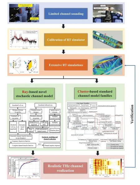
Figure 1.Framework for realizing realistic THz channel.
II.PARADIGM OF REALISTIC 6G THZ CHANNEL MODELING
As illustrated in Figure 1,the paradigm for THz channel modeling is composed of the limited channel sounding,calibration of RT simulator,extensive RT simulations,ray-based novel stochastic channel model,cluster-based standard channel model,and realistic THz channel realization.
2.1 Limited Channel Sounding
There are two essential alternatives of THz channel sounding-using vector network analyzer(VNA)and using channel sounder.The major difference is the domain in which the measurements are done.As described in Figure 2,VNA measures channel transfer functions(CTFs)for the narrow sub-band sequentially in the frequency domain.The whole broadband CTF is attained by aggregating all sub-band CTFs.The corresponding broadband CIR is transformed through the inverse fast Fourier transform(IFFT)from CTF.Contrarily,a correlation-based channel sounder transmits directly a broadband maximum length sequence(Msequence)as the reference.The autocorrelation function of the M-sequence in the time domain is Diracimpulse shaped.Thus,the broadband channel impulse response(CIR)can be obtained through the correlation function of the transmitted M-sequence and the received signal.
Each channel sounding method has pros and cons[27].Each channel sounding method has pros and cons.For instance,the VNA-based approach has accurate sub-band channel measurements because of the low measurement noise and the individual calibration method for each frequency point.Thus,the broadband CTF is accurate as it is composed of many sub-band measurements.On the other hand,this frequencydomain feature makes the measurement duration long,and therefore,the dynamic channel variations,such as those caused by the Doppler effect,cannot be captured.For the time-domain channel sounder methodology,it can take measurements in real-time so that the dynamic channel effects can be measured in theory.But,due to the strong thermal noise by the large measurement bandwidth at THz,which is very limited by the semiconductor technology,the results are not easy to capture the dynamic variations.To summarize,channel sounder provides more potential but is limited by current semiconductor technology.But still,no matter using which method,the THz channel sounding data is not comparable with the sub-6 GHz channel in terms of both data amount and degrees of freedom.In the following two case studies,each of the channel sounding methods will be utilized,respectively.
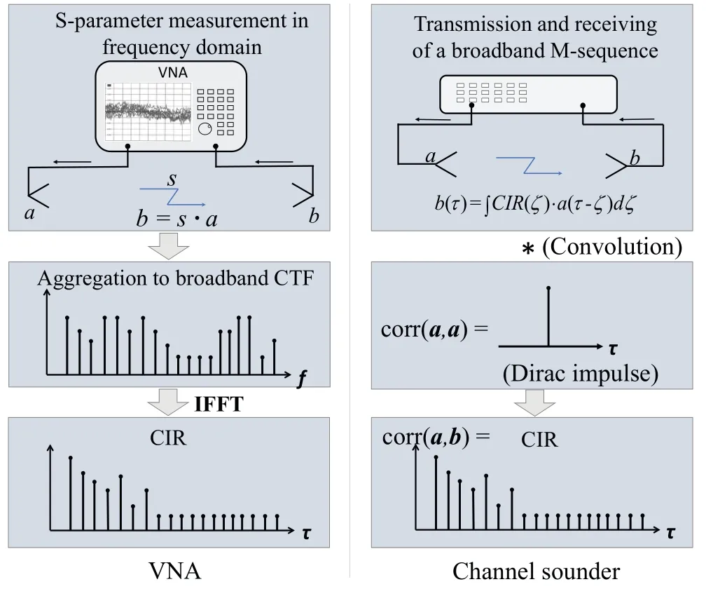
Figure 2.Measurement methodologies of VNA(left)and correlation-based channel sounder(right).
2.2 Calibration of RT Simulator
As a representing deterministic channel modeling approach,RT becomes increasingly prominent in 5G and 6G communications.Since computational complexity is always the bottleneck of conducting RT simulations in realistic communication scenarios,a promising solution is to develop the RT that can be deployed on high-performance computing(HPC)platforms.This will effectively speed up the compute-intensive tasks via parallel hardware technology.In this study,we take-CloudRT[28]-a self-developed HPC cloudbased RT simulator as an example.
The precondition of employing RT simulators to do extensive simulations is to calibrate it with the limited channel sounding data.According to the well-known Fresnel formula as described in[29],the reflection coefficient is determined not only by geometry but also the real and imaginary parts of the relative permittivity(and).Thus,these two parameters of all the relevant materials need to be calibrated through minimizing the error of the power of the significant paths(reflected rays)between measurements and RT simulations.The initial values of EM property can be obtained from open literature(for instance,metal and rubber[30],glass[31],brick[32,33]).Then,by using simulated annealing algorithm[34],the corresponding values of relevant materials can be calibrated.Apart from this,the geometric characteristics of the environment model need to be calibrated as well;otherwise,the time of arrival(TOA)of multipaths will not agree between measurements and simulations.After calibration,the RT simulator can be utilized for extensive simulations.
2.3 Extensive RT Simulations
As already discussed above,the THz broadband channel sounding is usually realized by two-dimensional(2D)scanning mechanisms using directional antennas.Thus,the channel needs to be characterized more comprehensively by using the validated RT simulator,which can effectively enhance the generality of scenario setup and the channel degrees of freedom in terms of:
1.Various positions of Tx and Rx;
2.Full polarization combinations;
3.Various pattern coupling,including single antenna,multiple-input multiple-output(MIMO),and massive MIMO;
4.Various environments with similar types of objects and materials,but not necessary with the same geometry or topology;
5.Various mobility patterns not only for Tx/Rx but also for mobile scatterers,such as vehicles,aircrafts,pedestrians.
After extensive RT simulations conducted with various configurations in the above aspects,a panorama of full-dimensional THz channel for specific 6G use cases can be formed.
2.4 Ray-based Novel Stochastic Channel Model
Based on the extensive realistic channel data,there are two options for channel modeling-ray-based novel stochastic channel model or cluster-based standard channel model.For the ray-based modeling,the core is to stochastically generate the CTF of the entire channel based on the information of all the rays in terms of time,frequency,delay,polarization,and angle,coupling with Tx/Rx antennas[35-37].
2.5 Cluster-based Standard Channel Model
As already mentioned above,the cluster-based channel modeling approach has been widely utilized by 3GPP standardization community,spawned entire standard channel model families.With the required channel parameters,e.g.,PL,SF,KF,DS,ASA,ASD,ESA,ESD,etc.,from RT simulation results,the cluster-based standard channel models can generate corresponding channel data in the target scenario without running RT simulations or doing measurements.
2.6 Realistic THz Channel Realization
Surely,compared to RT simulations or channel sounding,the stochastic models based can achieve a higher generality and can generate the channels much faster.Thus,a huge mass of realistic THz channel data can be obtained for various levels of simulations.Last but not least,since the stochastic models(no matter the ray-based or cluster-based)are the simplification of RT.Hence,channel characteristics extracted from the model should be verified by RT simulations.This realization and verification part will be demonstrated in the case studies.
III.CASE STUDY FOR REALISTIC THZ CHANNEL MODELING FOR CLOSEPROXIMITY COMMUNICATIONS
A typical example of close-proximity communications is defined as“kiosk downloading”,which is considered as an important application in the airports,train stations,and metro stations.As shown in Figure 3,the propagation distance of kiosk downloading is in the order of centimeters and the channel is mainly determined by the placements of the transceivers and the design of the kiosk stations.
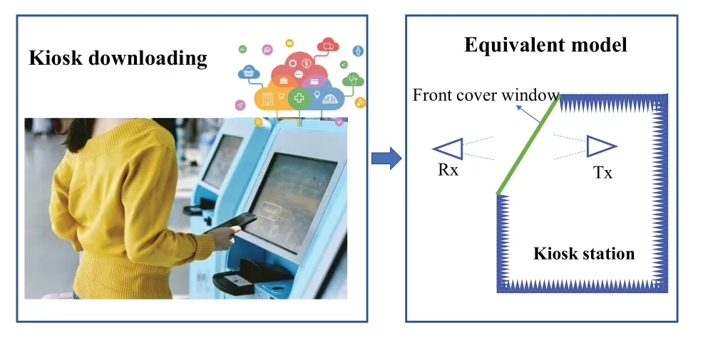
Figure 3.An example of close-proximity communications defined as“kiosk downloading”.
At first,to carry out the paradigm is the module of“limited channel soundings”.An Agilent Technologies N5245A VNA with VDI mmWave extenders is utilized to support the measurement frequency range from 220 to 340 GHz.1561 frequency points are measured.The intermediate-frequency(IF)bandwidth is 5 kHz,which is enough to reduce the noise and to improve the dynamic range.The S-parameter-S21-is recorded for characterizing the distance-varying measurements.One exemplary measured power delay profile(PDP)of one snapshot is illustrated in Figure 4.More details can be found in[38].
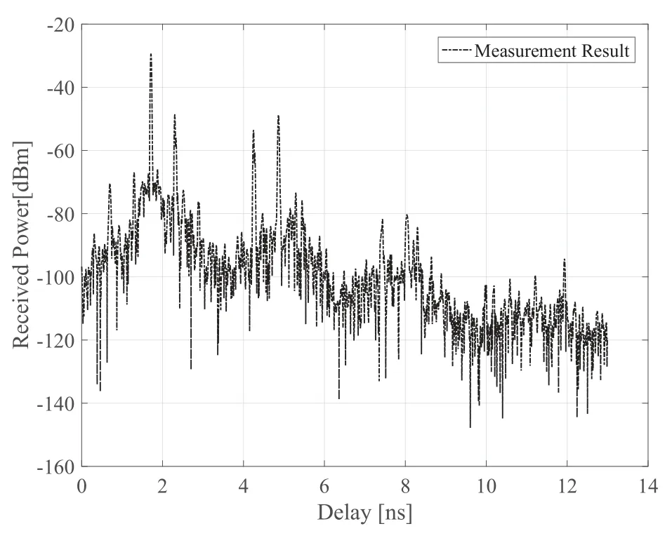
Figure 4.The measured PDP of the kiosk channel.
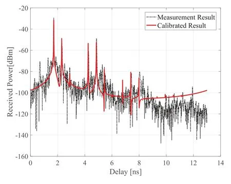
Figure 5.The comparison of PDP between the calibrated RT and measurement,originally from Figure 5(b)of[38].
Secondly,the module of“calibration of RT simulator”is implemented by RT simulations,in which we set the same configuration as the measurements.For the 120 GHz bandwidth with 1561 frequency points,the maximum excess length is 3.9 m,which is long enough for the kiosk downloading channel.Initially,the LOS ray and reflected rays(up to the 6th order)are traced in the RT simulations.The metal plates surrounding Tx and Rx are assumed to be perfect electric conductors(PECs)with the relative permittivity ofε′=1,ε′′=107.The EM properties of polyethyleneterephthalate(PET)are considered to be calibrated,including the penetration loss and its relative permittivity.The initial penetration lossAPETis set to be 2 dB and the relative permittivity isε′=6.4,ε′′=0.749.With the initial parameters,the delay of each significant ray in the simulations matches well with the measurements,which implies the accuracy of the geometric model.Even though,the mean absolute error(MAE)of the amplitudes between the simulations and measurements is larger than 5 dB.A genetic algorithm is utilized to find the best values of the EM properties of PET to minimize the MAEs between the measurement and simulation results.The calibrated EM properties of the PET areAPET=1.97 dB,ε′=2.1899,andε′′=0.2599.With the calibrated EM properties,MAE of the amplitude is decreased from 5 dB to 0.99 dB.The comparison of PDP between the calibrated RT simulation and measurement results can be seen in Figure 5,from which it can be seen that the calibrated RT simulator can accurately describe and reproduce the kiosk downloading channel measurements in a statistically significant way.
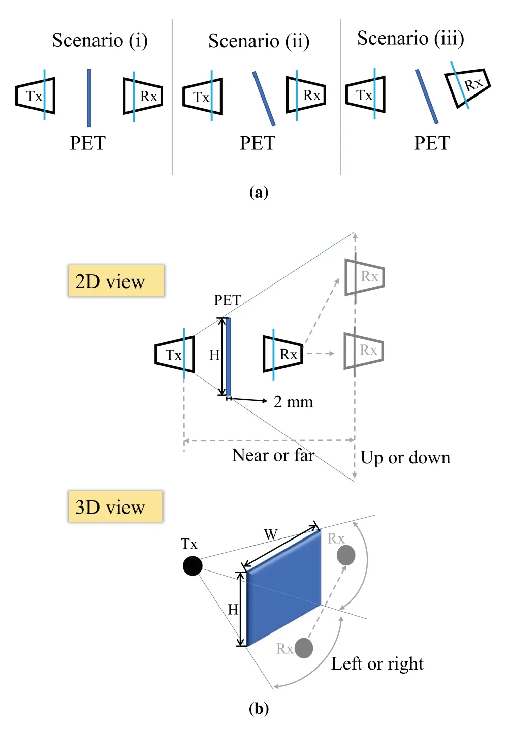
Figure 6.(a)The possible three kiosk downloading scenarios;(b)the 2D and 3D view of Rx position in the extensive RT simulations.
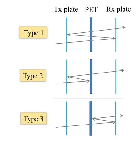
Figure 7.Three types of the reflected rays.
Due to the limitation of the measurement equipment,the measurements at different positions cannot be realized.Thus,the calibrated RT simulator can be used to bring more degrees of freedom to channel data in order to imitate the various positions of users’devices.This step is“extensive RT simulations”in the proposed paradigm correspondingly.As shown in Figure 6,three detailed kiosk downloading scenarios and Rx positions are defined in the extensive simulations(details see[38]).
After the step of“extensive RT simulations”,the kiosk downloading channel is modeled by the“raybased”stochastic approach.To generate the multipath CTFs,all the significant rays should be modeled.By doing significance analysis,it can be found that the direct transmitted ray and the 2nd order reflected rays are crucial to determine the behaviors in the three scenarios.The direct transmitted path exists in all three scenarios.Furthermore,the 2nd order reflected rays can be distinguished into three types as shown in Figure 7.The reflected rays of Type 1 always exist in Scenario(i)and(ii),yet do not occur in Scenario(iii).The reflected rays of Type 2 exist in the three scenarios with the possibilities of 100%,80%,and 97%,respectively.The reflected rays of Type 3 occur in the three scenarios with the possibilities of 100%,53%,and 33%,respectively.Detailed equations of the established“ray-based novel stochastic channel model”can be found in[38].
At last,in the module of“realistic THz channel realization”,we generate 100 channels for each snapshot in each scenario.The MAEs of Rician K-factor and RMS delay spread are 1.48 dB and 0.04 ns,respectively.This good agreement validates the developed channel model.
IV.CASE STUDY FOR REALISTIC THZ CHANNEL MODELING OF WIRELESS CONNECTIONS ON A DESKTOP
At the beginning of the proposed paradigm,a typical LOS channel on an optical table is measured for the module of“limited channel soundings”.A VNA with mmWave extenders is applied to measure the channel at 330-365 GHz with 5001 frequency point.The corresponding sampling intervalΔfis 7 MHz.With such a measurement configuration,the corresponding delay resolution is 0.029 ns,which is short enough to distinguish the multipath components(MPCs).Besides,the corresponding maximum excess delay is 143 ns,and therefore,it is long enough to capture MPCs in the desktop channel.The utilized antennas are with the gain of approximately 24 dBi and with the HPBW of theoretically 10°.The full two-port calibration approach-Short,Open,Load,and Thru(SOLT)-is applied for the calibration of the entire measurement system,including the waveguides,mmWave extenders,cables,and surely the VNA itself.As shown in Figure 8,a desktop THz channel with approximately onemeter length is measured in a typical laboratory scenario.
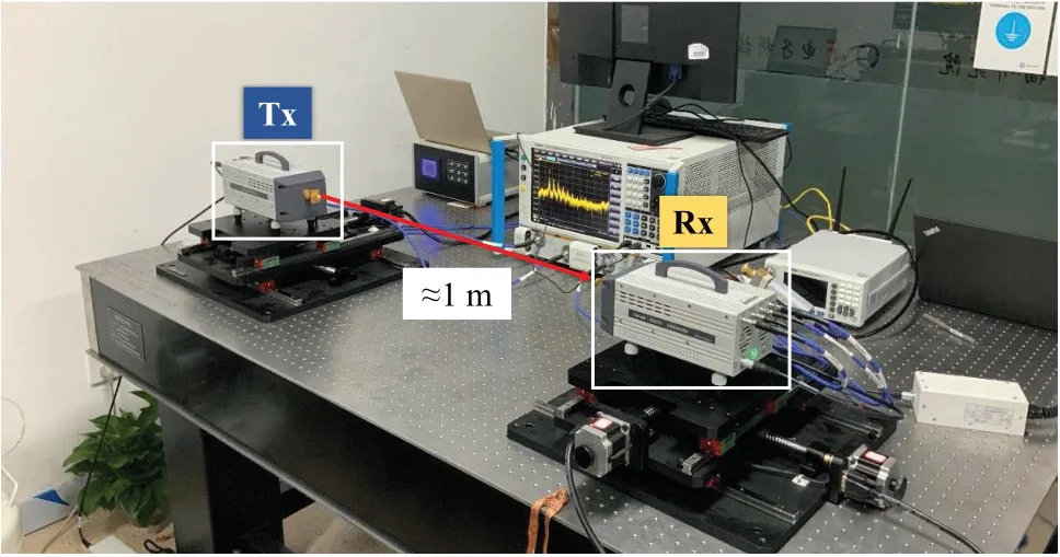
Figure 8.Measurement setup for the desktop THz channel.
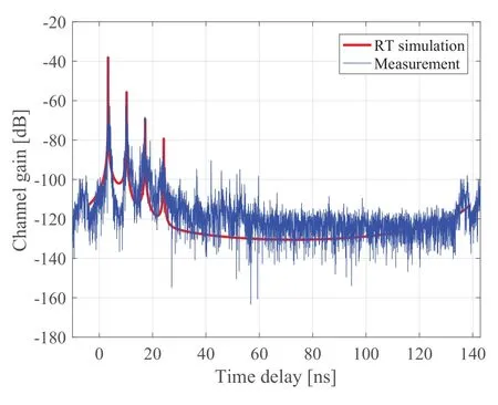
Figure 9.Comparison of the channel gain between measurement and calibrated simulation for the desktop channel.
Next,the module of“calibration of RT simulator”is started through RT simulations.The simulation configuration remains unchanged with the measurement configuration.At the beginning of the simulation,the LOS ray and up to the 6th order of reflected rays are simulated in the desktop THz channel with 35 GHz bandwidth.The metallic optical table is assumed as PEC and meanwhile,the painted metallic plate of the extenders,which can be treated as the hardware design of the handheld devices and laptops,need to be calibrated.The EM properties of the painted metallic plate after calibration are with the values ofε′=1.05 andε′′=12.075.As shown in Figure 9,the errors of each significant traced rays in power domain are smaller than 1 dB.Meanwhile,the errors are smaller than 0.1 ns in time domain.The traced rays are mainly reflected from the surfaces of devices.In good agreement with the simulated and measured results,the calibrated RT simulator can correctly repeat the desktop channel measurement.
The same as the“kiosk downloading”case,users have more freedom as a matter of fact and might place the devices on the desktop in different locations.However,due to the limitation of the measurement equipment,the comprehensive measurements are too difficult to be conducted and the possible alternative way is with the aid of RT simulator to generate the channel data,mainly the abundant CIRs.Therefore,to carry on the module of“extensive RT simulations”,we place the fixed Tx on one side of the table.To find the correlation between the snapshots,the sampling interval of Rx is set to be 0.8 mm,which is approximately equal to the wavelength of the center frequency.The simulated communication distance range is between 0.2 m and 1.5 m for a typical desktop channel.
In order to generate realistic THz channels by“cluster-based standard channel model families”,the key parameters should be extracted from the RT simulation results.The key parameters illustrated in Table 1 are in log-normal distribution,which is in accord with the distribution of 3GPP-like channel model families.In Table 1,μXandσXdenote the mean value and the standard deviation of theXparameter(Xcan be DS,KF,SF,ASD,ASA,ESD,and ESA),respectively.The path loss is fitted by“AB”model(PL=A·log10(d)+B+ΔXσ),in whichAandBrepresent the slope and interception of the fitted curve,respectively;drepresents the distance between the transceivers.ΔXσrepresents the shadowfading which is following the standard normal distribution.The fitted values ofAandBare 19.21 and 80.03,respectively.Due to the sparsity of THz channel and with the aid of the power k-means clustering algorithm,the per-cluster parameters for 3 clusters of the desktop channel are determined and listed in Table 2.As a consequence of the THz short wavelength,the large-scale parameters are very sensitive to the environment when Rx move through the scenario,and therefore,the decorrelation distances of KF,DS,and four angular spreads are 0.0216 m,respectively.The decorrelation distance of SF is 0.0024 m.The fact indicates a much shorter correlation length in the propagation scenario compared to the sub-6 GHz band and mmWave band,which have a major influence on the link-and system-level design.After feeding all these parameters into the quasi deterministic radio channel generator(QuaDRiGa)[7],which is a 3GPP reference channel generator following the geometry-based cluster stochastic channel modeling,the realistic THz channel on the desktop can be realized in a much more straightforward way without intensive measurement data.

Table 1.Key parameters of desktop THz channel.

Table 2.Per-cluster parameters for desktop THz channel.
By running QuaDRiGa with the same deployment of the transceivers and the moving trajectory in the RT simulation,the last module“realistic THz channel realization”is trigged and validated.As shown in Figure 10,the comparisons between QuaDRiGa and RT in terms of RMS delay spread and ESA are as the examples.The differences between QuaDRiGa and RT of these two parameters are 0.14 ns and 0.33°,respectively.Both the delay-power domain and angular domain are in a good agreement,which indicates the proposed paradigm can reproduce the channel data generated by the calibrated RT simulator.Therefore,the extracted parameters can be used for producing more channel data without the complicated and timeconsuming RT simulations.
V.CASE STUDY FOR REALIZING REALISTIC THZ CHANNELS FOR SMART RAIL MOBILITY
As a vital vertical industry empowered by the reliable high data rate transmissions of 6G[42],“smart rail mobility”is expected to become reality from a concept[43,44].Table 3 summarizes the relevant scenarios and high-data-rate applications therein[18].Figure 11 illustrates the panorama of all the smart rail mobility scenarios,requiring the seamless wireless connectivity with the data rate on the order of 100 Gbps or even more,forming a strong driving force for exploiting the THz band,i.e.beyond 300 GHz,where there are huge continuous available spectrum resources[45,46].Without any doubt,to fully understand the propagation channel in these scenarios is of importance[27,17].
The first module of the paradigm is“limited channel sounding”,in which we use a UWB channel sounder[47]to do measurements in an HST test center for Inside station scenario[26]and Intra-wagon scenario[25].As stated in our recent study[48],this channel sounder can measure 17590 CIRs per second with a dynamic range over 30 dB at the 300 GHz band with an 8 GHz bandwidth.
Then,for the module of“calibration of RT simulator”,CloudRT is employed to run simulations in frequency domain[49,50].All the setup is in line with the measurement campaign.Following the procedure in Section 2.2,the real and imaginary parts of the relative permittivity of relevant materials are calibrated.
After calibration is“extensive RT simulations”.Detailed simulation setups and results of train-toinfrastructure(T2I)inside station and Intra-wagon can be found in our previous study[26]and[51],respectively.Thus,in this paper we take the train-to-train(T2T)channel as a new example to implement the proposed paradigm.Figure 12 illustrates the rays in onesnapshot in a typical T2T communication scenario according to the vision of“virtual coupling”[40].

Table 3.Smart rail mobility scenarios and high-data-rate applications therein.
Since“smart rail mobility”is a typical mobile communication use case,it falls into the scope of 3GPP and therefore,we choose to implement the module of“Cluster-based standard channel model families”.The most important is to extract the input parameters of those 3GPP-like channel generators.Similar to the T2I Inside station case[26]and the Intra-wagon case[51],the T2T channel characteristics are summarized in Table 4.The decorrelation distances of them are listed in Table 5.The power k-means clustering approach is applied to determine the 5 clusters in the T2T channel with the key parameters per cluster listed in Table 6.
For the path loss fitted by“A-B”model,the slopeAof the T2T channel is only 9.10,much smaller than the free space propagation,indicating that apart from the clear LOS ray,the multipaths from the ground,from the fronts of the trains,and from catenary masts contribute a lot of power as well.But still,the LOS ray is very much dominant,and therefore,theμKFof the T2T channel is as large as 12.97 dB and theμDSis as small as 0.87 ns,implying a very good propagation condition.The observation in the angular domain is very interesting.Usually,for the T2I channels,no matter for mmWave band(in our previous work[52])or for the THz band,the angular spreads in the azimuth plane are larger than those in the elevation plane.But,for the T2T channel,theμASAis 0.34 dB and theμASDis 1.05 dB;while theμESAis 1.51 dB and theμESDis 1.50 dB.This reversed relation reflects an important feature of the T2T channel-the multipaths from the catenary masts(vertical planes),from the ground,and from the fronts of the trains are more dominant than the multipaths in the azimuth plane.Thus,the MIMO system design for T2T communications should differ from the case of T2I communications.TheμXPRof the T2T channel is 3.31 dB,which means that the depolarization in this case is not severe.
The last module is“realistic THz channel realization”,in which large-scale channel data is generated by QuaDRiGa with the same deployments of Tx,Rx,and their mobility patterns to those in RT simulations.Figure 13 compares the PL,SF,and the cumulative distribution function(CDF)of Rician K-factor between QuaDRiGa and RT simulations.It can be seen from the good agreement that,the paradigm proposed in this paper is capable to generate realistic THz channels for T2T scenario in the smart rail mobility.
VI.NEW CONCERNS OF THZ CHANNEL MODELING
Despite the pleasing vision of THz communications and the feasible THz channel modeling approaches,when it comes to the THz band,new concerns will be faced because of the distinguishing features of THz wave.Besides the high propagation and transmission loss compared to the lower frequencies,the impact of meteorological factors,the beam split effect related to the antenna array,and multi-fold noises should be noticed.In this part,we discuss new concerns of THz channel modeling regarding propagation,antenna array,and device aspects.
6.1 Propagation Aspect--Meteorological Impact
Compared to the wireless channels at lower frequencies,channels at THz bands are more vulnerable to different meteorological factors,including atmospheric gases,fog,rain,and snow.In order to satisfy the requirement of global coverage for the new version of6G communications,terrestrial networks will be complemented by non-terrestrial networks.Among them,especially for the outdoor scenarios,such as vehicular communications[53],drone communications[54],satellite-ground communications,and so on,these meteorological impacts cannot be neglected in channel modeling.

Table 4.Key parameters of T2T THz channel.

Table 5.Decorrelation distance for T2T THz channel.

Table 6.Per-cluster parameters for T2T THz channel.
Atmospheric attenuation is due to the energy absorption by the atmospheric molecules.Since some excited molecules vibrate with the certain frequency,a portion of the EM energy is transformed into kinetic energy[55].The major gaseous molecules at THz band are the oxygen and the water vapor.The intensity of the atmospheric attenuation is determined by several items,including the temperature,pressure,altitude,and the wave frequency as well.Recommendation ITU-R P.676-11[56]gives the prediction method to evaluate atmospheric attenuation.Figure 14 shows the calculated attenuation curves from 0 to 1000 GHz for the standard atmosphere,oxygen,and water vapor,respectively.Thus,the atmospheric attenuation can define several significant transmission windows(such aswiin Figure 14),the position and width of which are mainly determined by the carrier frequency and the gas composition in the propagation environment,mostly the water vapor.Because of this feature,a new communication scheme,that can dynamically conform the waveform according to the carrier frequency and propagation distance,can be explored to match the window shape[57]and avoid the absorption narrow peaks.
When the THz communication comes to the outdoor scenario,not only the atmospheric gases but also the fog,rain,and snow should be considered according to the actual communication environment.The fog attenuation is mainly determined by the density of the liquid water in the air.Recommendation ITUR P.840-7[58]details the Rayleigh approximation to describe the specific fog attenuation.Compared with the great extra path loss in the infrared band,the fog attenuation at THz band is much lower,but still cannot be neglected.For thick fog(liquid water density:0.5 g/m3),the attenuation is about 7.26 dB/km.Mie scattering is caused when the particle size is comparable with the incident wavelength.With the increase of the frequency at THz band,the size of raindrops,snowflakes,and the THz wavelength are in the same scale.The study in[59]draws the conclusion that the rain attenuation increases with the density of the rainfall,whereas the temperature has little influence.The authors in[60]evaluate the rain attenuation prediction approach of ITU-R P.838-3[61]by comparing with the experiment results at 300 GHz.They find that not only the rainfall rate but also the drop size distribution need to be modeled to predict the rain attenuation.The snow attenuation is forecasted to be more serious,since the structure of snowflakes is fluffier,and is primarily made by air,liquid water,and ice.Because the unfriendly weather conditions can easily harm the sensitive and expensive measurement equipment,few studies on snow attenuation have been reported.The prediction method from ITU-R for snow attenuation is absent as well.The valuable measurement results in[62]show that the wet snow might cause larger attenuation in comparison with the dry snow.Besides,the wet snow may cause 3 times larger attenuation compared to the rain attenuation at the same falling rate.In[63],an 8-meter LOS path measurement was conducted in a significant snowstorm day.The measurement result implies that the snow attenuation is very significant with the value of 2.8 dB/8 m.
To the best of the authors’knowledge,until now,the various channel modeling approaches have not considered the impact of the different meteorological factors.Since the high spreading loss and considerable meteorological attenuation due to atmospheric gases,fog,rain,and snow,they should be a new concern in THz channel modeling compared to the channel modeling at lower frequencies.
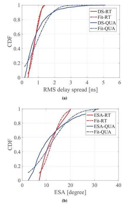
Figure 10.Comparison between QuaDRiGa and RT for desktop THz channel:(a)RMS delay spread,(b)ESA.
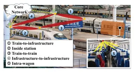
Figure 11.Panorama of smart rail mobility scenarios.
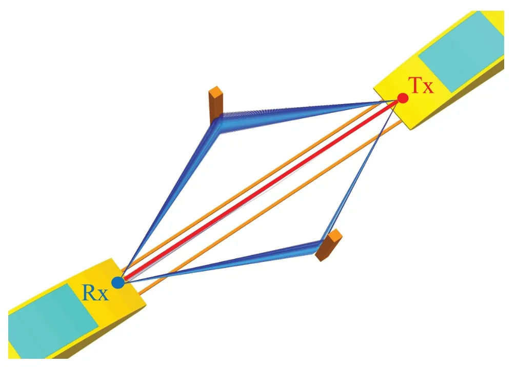
Figure 12.One snapshot of the RT simulations for T2T channel.
6.2 Antenna Array Aspect--Beam Split
For the compensation of the large propagation loss and meteorological attenuation,very large antenna arrays with phase-shifters(PSs)are widely considered in THz communications.Generally,the phase shift is determined by the carrier frequency and the corresponding wavelength.Since the PS is frequencyindependent,the directional beams are squinted to different directions at different subcarrier frequencies.This effect,which causes the loss of antenna array gain,is called beam squint in wideband mmWave systems.In THz band,the available bandwidth becomes larger,and meanwhile,the beam generated by the traditional frequency-independent PS becomes narrower.Thus,the beam squint effect will be significantly aggravated,where the beams at different subcarrier frequencies might split far away from the ideal direction.This misalignment effect,which is called beam split,will cause more obvious array gain loss at THz band,and therefore result in the undesirable deterioration of the data rate performance[64].The comparison between the beam squint effect at mmWave band and the beam split effect at THz band is shown in Figure 15.
The theoretical reason for these two effects is mainly because the antenna array withNelements introduces the array response vector as follows:
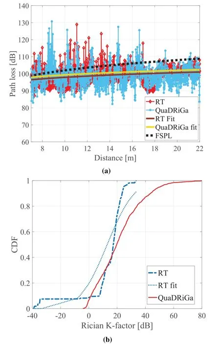
Figure 13.Comparison between QuaDRiGa and RT for T2T THz channel:(a)path loss,(b)Rician K-factor.
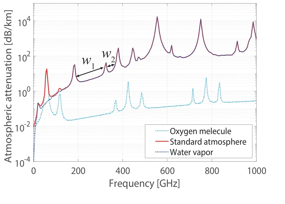
Figure 14.Atmospheric attenuation of the standard atmosphere,oxygen,and water vapor,respectively.

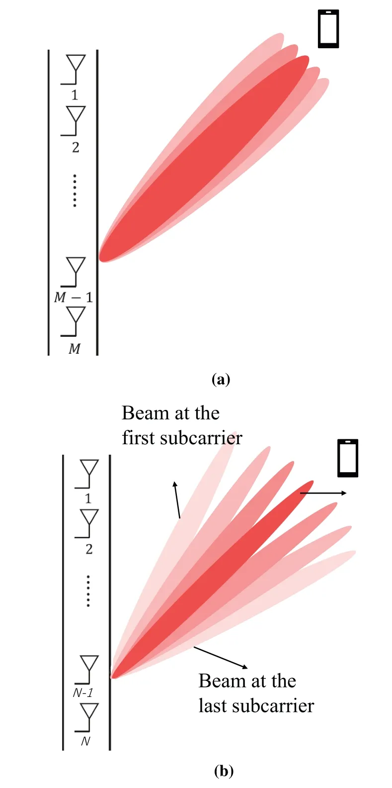
Figure 15.Beam effect:(a)Beam squint effect in mmWave,and(b)beam split effect at THz band.
whereθdenotes either AOA for receiving or AOD for transmission;θFis ideal beam focus angle;fcdenotes the center carrier frequency,andcdenotes the light speed.dis the distance of fixed adjacent antenna elements withd=The antenna array response varies with frequency across the ultra-wideband systems.The authors in[65]propose a delay-phase precoding method to fulfill frequency-dependent PSs through time delay.In the beginning,the PSs engender frequency-independent beams.Then,the time delay elements provide the beam compensation based on the user physical direction and the subcarrier frequencies.With accurate channel modeling and the fabrication of very large THz array with novel hybrid precoding methods,it is possible to achieve good performance and low power consumption in THz communication systems.
6.3 Device Aspect--Noise Impact
There are several noise sources which can affect the performance of THz communications.One major noise source is the phase noise,which can randomly lead to fast fluctuations in the phase of transmitting signals.The receiver will face a great challenge on processing synchronization and demodulation.Moreover,the thermal noise,which is caused by the irregular vibration of free electrons in conductors and semiconductors of the transceivers,needs to be taken into consideration.The average thermal noise power spectral density is as follows[66,67]:

in whichkB=1.38·10-23J/K is Boltzmann’s constant;Tedenotes the environment temperature assumed isotropically as 300 K usually.ħ=1.054·10-34J·s denotes the reduced Planck constant.When the conditionis satisfied,the average thermal noise power spectral density is approximately constant expressed as the well-known equationN0=kBTe[68].When the large frequency range of interest is from 0.1 to 10 THz,the influence of the frequency on thermal noise cannot be neglected anymore.Furthermore,in any transceiver device,the quantum noise is unavoidable and is proportional to frequency.Thus,the total noise power spectral density of an ideal linear amplifier or phase detector is the sum of the thermal noise and quantum noise expressed as[66,67]:

Figure 16 shows the plots of the thermal noise,quantum noise,and the total noise on log scale.Despite the frequency proportionality of the ideal total noise,it is proportional to the bandwidth as well,particularly in the ultra-wide bandwidth THz communication systems.Thus,the effect of multi-fold noises should be considered when the model generates realistic channels for THz communications.
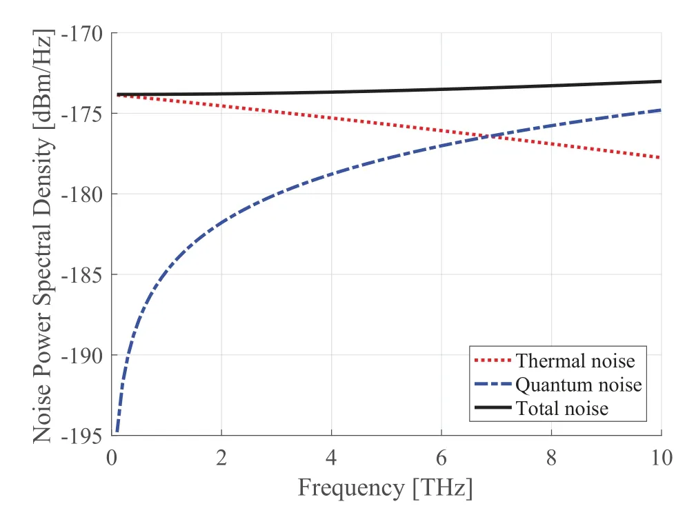
Figure 16.The comparison of the thermal noise and quantum noise at THz band.
VII.CONCLUSION
In this paper,a new paradigm is proposed for realizing the realistic THz channels towards 6G even when the extensive channel sounding measurements are absent.The paradigm is composed of six modules,which are limited channel sounding,calibration of RT simulator,extensive RT simulations,ray-based novel stochastic channel model,cluster-based standard channel model families,and realistic THz channel realization.In order to demonstrate how to implement this paradigm,three case studies are provided from a small-scale use case-close-proximity communications,to a mediumscale use case-wireless connections on a desktop,finally to a large-scale use case-smart rail mobility.With the aid of high-performance RT technique,i.e.CloudRT in this study,the proposed paradigm can exclusively break the bottleneck of acquiring realistic 6G THz channels.Either“ray-based novel stochastic channel model”or“cluster-based standard channel model families”has been validated by the RT simulations.With the“ray-based”modeling approach of kiosk downloading scenario,the MAEs of KF and DS are 1.48 dB and 0.04 ns,respectively.With the standard“cluster-based”modeling approach of the desktop channel,the MAEs of DS and ESA are 0.14 ns and 0.33°,respectively.In the T2T scenario,for path loss,the MAEs ofAandBare 0.38 and 0.74,respectively.The MAE of SF is 0.81 dB.All parameters in Table 1-2 for the“wireless connections on a desktop”scenario and Table 4-6 for the“smart railway mobility”scenario can be fed into the 3GPP-like standard channel models.Last but not least,we highlight new concerns in THz communication systems from the meteorological impact,beam split effect of large antenna arrays and multi-fold noise sources from devices themselves.Thus,this work schemes the foundation for future work which aims to streamline the design,simulation,and development of 6G THz communication systems.
ACKNOWLEDGEMENT
This work is supported by the Fundamental Research Funds for the Central Universities 2020JBZD005,NSFC under Grant(61771036,61901029,U1834210,and 61725101),the State Key Laboratory of Rail Traffic Control and Safety(Contract No.RCS2020ZZ005),Beijing Jiaotong University,the ZTE Corporation,State Key Laboratory of Mobile Network and Mobile Multimedia Technology,and Beijing Natural Science Foundation under Grant L201023.
- China Communications的其它文章
- Terahertz Wireless CommunicationS
- Channel Measurement and Path Loss Modeling from 220 GHz to 330 GHz for 6G Wireless Communications
- THz Channel Modeling:Consolidating the Road to THz Communications
- A 3-D Hybrid Dynamic Channel Model for Indoor THz Communications
- Wideband Channel Estimation for THz Massive MIMO
- Hybrid Precoding for Cluster-Based Multi-Carrier Beam Division Multiple Access in Terahertz Wireless Communications

