A 3-D Hybrid Dynamic Channel Model for Indoor THz Communications
Yan Zhang,Lei Zhao,Zunwen He
School of Information and Electronics,Beijing Institute of Technology,Beijing 100081,China
Abstract:To meet the demands for the explosive growth of mobile data rates and scarcity of spectrum resources in the near future,the terahertz(THz)band has widely been regarded as a key enabler for the upcoming beyond fifth-generation(B5G)wireless communications.An accurate THz channel model is crucial for the design and deployment of the THz wireless communication systems.In this paper,a three-dimensional(3-D)dynamic indoor THz channel model is proposed by means of combining deterministic and stochastic modeling approaches.Clusters are randomly distributed in the indoor environment and each ray is characterized with consideration of molecular absorption and diffuse scattering.Moreover,we present the dynamic generation procedure of the channel impulse responses(CIRs).Statistical properties are investigated to indicate the non-stationarity and feasibility of the proposed model.Finally,by comparing with delay spread and K-factor results from the measurements,the utility of the proposed channel model is verified.
Keywords:terahertz(THz)communications;indoor channel;molecular absorption;diffuse scattering;non-stationarity
I.INTRODUCTION
Over the past few years,wireless data traffic has expanded drastically at an exponential rate due to the unprecedented growth of mobile devices and multimedia applications.Wireless data rates of the forthcoming beyond fifth-generation(B5G)wireless communication systems will reach tens of Gigabits or even several Terabits per second in the next decade[1,2].Apart from more advanced physical layer solutions,expanding operating frequency bandwidth is imperative to reach such ultra-high data rates and meet massive wireless data traffic demands[3].However,the current radio spectrum up to 60 GHz has been heavily occupied by a plethora of wireless communication activities,leading to a severe scarcity of spectrum.As a result,researchers and industry practitioners turn their attention to higher frequency bands,such as the terahertz(THz)band covering the frequency range from 100 GHz to 10 THz.Although the applications and realizations of THz wireless communications are still in their infancy,THz is envisioned as a very promising frequency band for future wireless communication systems because of its attractive advantages.For instance,with strong directionality and limited transmission distance,THz outperforms lower frequencies in terms of communication security and anti-eavesdropping[4,5].
Nevertheless,in comparison to lower frequency bands,the THz band communications undergo severer transmission loss.Except for physically inevitable free space spreading loss,there exist high atmospheric molecular absorption and diffuse scattering attenuation for THz propagation[6].As the wavelength of THz wave is close to the size of air molecules,THz waves can resonate with molecules in the air,resulting in molecular absorption loss.Besides,since the wavelengths of THz waves are comparable to the roughness of building surfaces which are considered smooth at lower frequencies,the incident wave may be diffusely scattered into different directions.Therefore,diffuse scattering attenuation in the THz band is a crucial factor that cannot be ignored[7].In consideration of above significant transmission attenuation,indoor short-range environments are more suitable for THz wireless links than other scenarios[8].Moreover,large-scale antenna array along with high beam directionality and gain is needed to mitigate the high transmission loss[9,10].Prospective applications include wireless local area networks,high-speed data transmission between servers in data centers[11],intra-wagon communications[12],Kiosk downloading communications[13],and so on.In order to design and deploy reliable short-range THz wireless communication systems,it is of vital importance to develop suitable channel models in indoor scenarios.
So far,some investigations have been conducted to study the characteristics of indoor THz wireless channels.The existing channel models for THz links can be roughly divided into two categories,namely,deterministic channel models and stochastic ones.In light of ray-tracing techniques,deterministic models calculate the propagation characteristics of each ray separately,e.g.delay spreads,angular parameters,path attenuation,etc.By utilizing deterministic modeling approach,a unified multi-path THz model was developed in[6],which thoroughly investigated lineof-sight(LoS),reflection,scattering,and diffraction propagation cases.Moreover,based on Kirchhoff scattering theory and measurements,some diffuse scattering models were developed to analyze scattering loss on rough surfaces[14-16].Through commercial raytracing tool simulations and indoor channel measurements,power delay profile(PDP),power angle profile(PAP),and frequency selectivity properties of the indoor channels at some THz frequencies were studied[17,18].Nevertheless,although the abovementioned models can mimic the channels accurately,their structures are complicated,and using them to generate channel samples is time-consuming.Additionally,since the considered environments are static,these deterministic channel models cannot illustrate dynamic characteristics of practical scenarios.Besides,these channel models are site-specific,i.e.,it is difficult to generalize them to new scenarios.
Compared with deterministic models which are subject to the complete knowledge of the propagation environments,stochastic channel models are developed in a geometrically random way.Specifically,scatterers are randomly distributed in spatial geometry based on statistical properties extracted from extensive measurements.With high efficiency and acceptable computational complexity,the stochastic modeling approach was widely used in existing models for 5G and lower frequencies,such as WINNER+[19],3GPP[20],IMT-2020[21],QuaDRiGa[22],and so forth.However,these existing models cannot be directly applicable to the THz band since they do not capture the characteristics of THz propagation[23].As for the THz band,based on the stochastic channel modeling approach,a two-dimensional(2-D)channel model was established for short-distance deviceto-device communication[24].Besides,a stochastic indoor channel model from 275 to 325 GHz was introduced in[25],where the frequency dispersion,temporal and spatial characteristics of the channel were investigated.Moreover,a statistical multiple-input multiple-output(MIMO)channel model was proposed in[26],showing the dependency of sparsity and spectral efficiency on surface roughness.However,as the environment is static,the applicability of this model is limited.Additionally,a three-dimensional(3-D)channel model for indoor communications was proposed based on the geometry-based stochastic model(GBSM)method[27],whereas the multipath attenuation resulting from diffuse scattering on the indoor surfaces was not included.As a result,the aforementioned stochastic THz channel models which have not taken the THz propagation characteristics or timevarying channels into account cannot accurately represent the realistic THz channels.
In this paper,we propose a 3-D hybrid dynamic channel model for indoor THz communications.On one hand,transmission attenuation is calculated for each path based on the deterministic method.Because the multipath components(MPCs)in the THz indoor channel are sparse[28],the computational complexity is acceptable.On the other hand,in light of the stochastic modeling approach,we present the dynamic generation process of channel impulse responses(CIRs).The movements of the clusters and/or the mobile station(MS)are considered to build a nonstationary model.Finally,the correctness of the proposed model is verified by statistical properties and measured results.
The main contributions and novelties of this paper are summarized as follows.
·We propose a 3-D dynamic channel model for indoor wireless communications in the THz band.Clusters and transceivers are assumed to be moveable,which gives rise to non-stationarity of the channels.The birth-death properties of clusters are characterized and time-varying parameters are generated.Besides,we intuitively show the transition between reflection and scattering on the rough surface due to the movement of receiver.
·A novel modeling scheme is developed,where the deterministic and stochastic modeling methods are applied in a hybrid way.Three types of rays,including LoS,reflection,and scattering ones,are taken into consideration.On one hand,the clusters and the rays in each cluster are statistically characterized.On the other hand,each ray is generated separately based on the propagation distance,molecular absorption,and diffuse scattering loss.
·We verify the proposed model by comparing the generated delay spread and K-factor results with the THz-band measured data.Besides,some statistical properties are obtained to investigate the feasibility and non-stationary characteristics of the proposed channel model.
The rest of this paper is organized as follows.The detailed descriptions of the proposed 3-D hybrid dynamic channel model are introduced in Section II.Section III presents the non-stationarities of the model with time evolution.Section IV presents the derivations for some statistical properties of the proposed model.Next,results and validation of the channel model are illustrated in Section V.Finally,conclusions are drawn in Section VI.
II.A 3-D TIME-VARYING INDOOR CHANNEL MODEL IN THE THZ BAND
In this section,the proposed 3-D time-varying indoor channel model in the THz band will be presented.To start with,we illustrate the geometry of the proposed model and some basic geometric formula derivations.Afterward,the whole generation procedure of the CIRs of our proposed model will be given.Unlike the classical stochastic models,the large scale and small scale characteristics of each ray will be combined and calculated simultaneously in our model.Two critical features of THz wave propagation,i.e.,molecular absorption and diffuse scattering on rough surfaces,will be elaborated.
2.1 Descriptions of the Proposed Model
Consider an indoor environment where a base station(BS)as transmitter(Tx)communicates with an MS as receiver(Rx)via downlink in the THz band.By means of considering the peculiarities of THz propagation,a 3-D hybrid channel model in the THz band based on GBSM can be established.As shown in Figure 1,both BS and MS are equipped with MIMO antenna arrays which have uniform rectangular array(URA)layouts.In general,LoS ray exists in the THz wireless propagations.As the effect of diffuse scattering is significant in the THz,non-line-of-sight(NLoS)propagations need to be investigated thoroughly.It is worth mentioning that only up to double-bounces are considered in the proposed model,since each reflection introduces tens of dB attenuation so that the third and higher order reflections have a limited impact on the THz channel characteristics[25,29].Most of the NLoS propagations in indoor scenarios are single-bounces,and the double-bounces only account for a small proportion[18].Assuming that there areNMPCs in the channel,which incorporateNssingle-bounces andNddoublebounces(N=Ns+Nd).Each MPC corresponds to one or two clusters and consists ofMrays,which are modeled as scattering tiles(STs).Let clustersdenote thesth(s=1,2,...,Ns)cluster corresponding to thesth single-bounce.Besides,let clusterddenote thedth(d=1,2,...,Nd)pair of clusters corresponding to thedth double-bounce.Specifically,clusterdincorporates clusterTdat the Tx side and clusterRdat the Rx side[30].For single-bounce,STs,mrepresents themth(m=1,2,...,M)ST within the clusters.As for double-bounce,let()represent themth ST within the cluster(cluster).The superscripts T and R denote the parameters at the Tx and Rx sides,respectively.In indoor communication scenarios,obstacles,such as plaster walls,ceiling,floor,walking people,etc.,can be viewed as clusters.
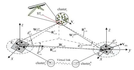
Figure 1.Geometry illustration of the proposed 3-D hybrid channel model for the THz band.
To capture the dynamic characteristics of the propagation channel,we assume that MS moves at the velocity of VMS,BS is fixed and clusters(clusterd)moves at a velocity of Vs(Vd),which are consistent with the practical environments.As for some static clusters,such as walls and ceiling,the velocity can be set as zero.Moreover,the movements of MS and/or clusters result in time-varying channel parameters and non-stationary channel coefficients[31].For the sake of notational clarity,a global coordinate system(GCS)and a local coordinate system(LCS)need to be established.In Figure 1,let the center of BS antenna array,O,and that of MS antenna array,OM,be the origins of GCS and LCS,respectively.The LoS path vector fromOtoOMis denoted as RLoS(t).As for the NLoS cases,the geometrical relationships of single-bounces are firstly presented,and that of double-bounces can be derived by using similar methods.
For the single-bounce cases,the path vector fromOto the center of clusterswith the time-varying azimuth angle of departure(AAoD)(t)and elevation angle of departure(EAoD)(t)is denoted as vector(t).The distance betweenOand the center of clustersis(t),which follows the exponential distribution.In terms of STs,m,the position vector is denoted as(t).By adding increments of the corresponding angular parametersthe 3-D angular parameterscan be obtained as


whereis the distance betweenOand STs,m.Likewise,represents the path vector fromOMto the center of clusterswith the time-varying azimuth angle of arrival(AAoA)(t)and elevation angle of arrival(EAoA)(t).Also,the path vector fromOMto STs,mwith AAoA(t)and EAoA(t)is represented as(t),which can be calculated by

In the Tx and Rx antenna arrays,andrepresent the position vectors of thepth antenna element of BS in GCS and theqth antenna element of MS in LCS,respectively.The ray vectors from thepth antenna element of BS to STs,mand from STs,mto theqth antenna element of MS can be represented asandrespectively,which are computed as

In a similar way,the LoS ray vector from thepth BS antenna element to theqth MS antenna element,WLoS(t),is given by

Additionally,the scalar forms ofandare represented asandrespectively.Besides,the unit vectors of WLoS(t),are denoted asrespectively.
For the double-bounce cases,as shown in Figure 1,thedth MPC is double-bounced by clusterand cluster.These two clusters are connected via a virtual link,in which the rays within clusterand clusterare coupled randomly[32].The position vector fromOtocan be obtained by using methods similar to(1)-(2).Likewise,the position vector fromOMtowith AAoAand(t),can be expressed as

whereis the distance betweenOMandIn addition,the ray vectorscan be obtained based on(4)-(5).
2.2 Channel Impulse Response Generation
In classical stochastic models,large scale and small scale parameters are considered and generated independently.The power is allocated to clusters based on their delays,and the rays within the same cluster have equal power.However,in the THz band,each ray within a cluster experiences different diffuse scattering on the rough surface.In order to mimic the THz channel accurately,the characteristics of each ray are investigated individually within the proposed model.Particularly,the calculations of path gain of each ray will be divided into three cases:LoS,reflection,and scattering.
The CIR between thepth Tx antenna element and theqth Rx antenna element is a sum of LoS,singlebounce,and double-bounce components.Thus,the CIRhq,p(t,τ)can be calculated as
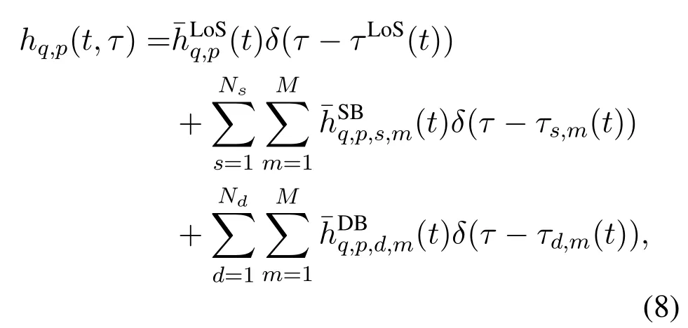

τd,min(11)is the delay of the virtual link and can be drawn with exponential distribution[19]

whererτis the delay factor,στis the delay spread of the channel,andXd,mis uniformly distributed within(0,1).
Due to the motion of MS and clusters,delays and distances between Tx and Rx are time-varying.LoS channel coefficient,the NLoS channel coefficient with clusterE,are derived as
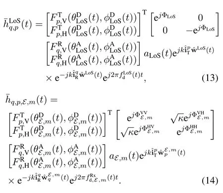
Here,E∈{s,d}.For single-bounce(E=s),Meanwhile,represents(t)for double-bounce(E=d).θLoS(t)andφLoS(t)denote the azimuth and elevation angles of the LoS ray,respectively.The superscripts of D and A correspond to the departure and arrival angles,respectively.andrepresent the field patterns of thepth Tx antenna element in the GCS for vertical and horizontal polarizations,respectively.Similarly,andrepresent the field patterns of theqth Rx antenna element in the LCS for vertical and horizontal polarizations,respectively.Moreover,ΦLoSis the random initial phase for the LoS ray andare the random initial phases of themth ray in clusterEfor four different polarization combinations.The initial phases are uniformly distributed in(0,2π].Additionally,κin(14)denotes the cross-polarization power ratio.are the unit vectors of,respectively.kis the wave number.What is more,are the time-varying Doppler frequencies of the Rx antenna via LoS and NLoS rays,respectively,which can be derived as

where〈·,·〉means the inner product operation.
Additionally,aLoS(t)andaE,m(t)in(14)are the path gains of the LoS and NLoS rays,respectively.Subsequently,the path gain will be classified into the LoS and NLoS cases for further detailed analyses.
2.2.1 LoS Ray
Without any obstacles between Tx and Rx,the signal is propagated via the LoS path.In contrast to the lower frequency band,THz waves suffer severer free space spreading and molecular absorption attenuation.Therefore,the path gain of LoS can be obtained by

whereaspr(t)denotes the path gain caused by free space spreading and can be calculated as

Here,cis the speed of light andfis the frequency of the signal.Moreover,ama(t)in(17)is the path gain due to molecular absorption,which is determined by the compositions of the air,temperature,pressure of the propagation environment,and frequency of the transmitted signal.ama(t)is expressed as[6]

whereKfdenotes the absorption coefficient,which is mainly caused by atmospheric molecules and varies with carrier frequencyf.Among these molecules in the air,water vapor molecules play a dominant role in affecting the molecular absorption loss in the THz band[33].In order to show the influence of water vapor absorption loss on path gain,LoS path gainALoS(t)in dB can be calculated as

LetWLoS(t)=1 m.Water vapor density is 2.6% by volume(the tropics in the summer).Kfof different frequencies in this specific environment can be obtained from the HITRAN database[34].Then,LoS path gain per meter with and without water vapor absorption can be visualized in Figure 2.Compared with the case without considering the molecular absorption loss,transmission attenuation resulting from molecular absorption is rather high.Thus,the molecular absorption should not be neglected for the THz channel models even in indoor environments.
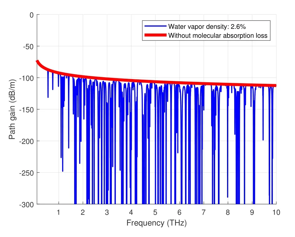
Figure 2.Comparison of LoS path gains with and without water vapor absorption.
2.2.2 NLoS Ray
Due to the fact that the wavelengths of THz waves are comparable to the roughness of reflected surfaces,diffuse scattering loss is significant in the THz band.Based on the idea of geometric optics,NLoS path can be divided into three categories,including reflection,scattering,and diffraction.It is noteworthy that diffraction is ignored here as the diffracted propagation loss is too high in the THz band[6,35].Given that a beam of THz wave is incident on a rough surface depicted in Figure 3a,where the incident wave is scattered into both specular and other directions.Accordingly,the simplified geometry of diffuse scattering is illustrated in Figure 3b,in whichθin(t)denotes incident angle,θout(t)andφsca(t)are elevation and azimuth angles of the scattered ray,respectively.Due to the movements of the clusters and/or MS,these three angles are time-varying.
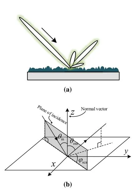
Figure 3.(a)Schematic diagram of diffuse scattering on a rough surface.(b)Simplified geometry of diffuse scattering on a rough surface.
In terms of NLoS path gain,the free space spreading and molecular absorption losses should be considered as well.By adding the attenuation due to diffuse scattering,the path gainaE,m(t)can be calculated.
For single-bounce cases,the path gainas,m(t)can be expressed as

whereaspr(t)andama(t)can be obtained by replacing the length of LoS path in(18)-(19),WLoS(t),with the length of single-bounce path,η(t)denotes the diffuse scattering coefficient.The value ofη(t)depends on the propagation case,which can be expressed as

In reflection case,θin(t)=θout(t)andφsca(t)=0.In light of Kirchoff scattering theory,the reflection coefficient can be calculated as[6]

where Fr(t)is the Fresnel reflection coefficient and can be given by

wherentis refractive index.In addition,ρr(t)denotes Rayleigh roughness factor,which is obtained by[16]

whereρhrepresents the root mean square(RMS)height of rough surface andλis the wavelength.
In scattering case,θin(t)/=θout(t)orφsca(t)/=0.The scattering coefficient can be derived as[6]

where Fr(t)has the same expression as in(24)andρs(t)denotes the scattering loss factor,which can be referred to[15].
In order to calculate the single-bounce path gain,it is necessary to first obtainθin(t),θout(t),andφsca(t),and then determine whether reflection or scattering has occurred.We assume that each ST is a small independent reflection surface as shown in Figure 3b.Based on reflection surface of STs,m,the LCS can be established and denoted as LCSs,m.To clarify the calculation procedure of incidence and reflection angles of each ray,the coordinates of vectors in GCS should be transformed into the ones in LCSs,m.Consider a 3-D rotation of the LCSs,mwith respect to GCS,which is given by three rotation angles,αs,m,βs,m,andγs,m.Given the randomness of height fluctuations of rough reflected surfaces,it is reasonable to assume that the three rotation angles are uniformly distributed in(0,2π].Nevertheless,if thezaxis orientation of the LCSs,mis in the opposite direction of Tx and Rx,the signal is impossibly transmitted to the Rx through STs,m.Therefore,the range of rotation angles needs to be modified unless the orientation of the LCSs,mmeets the above requirements.Particularly,when EAoD ofi.e.,STs,mis at the above of the GCS,βs,mshould be modified to be uniformly distributed in(π/2,3π/2).Whenβn,mis restricted in the range of(0,π/2)∪(3π/2,2π).
Let Qs,mdenote the rotation matrix of LCSs,mwith respect to GCS,which can be derived using the three rotation angles.Then,the vector of incident rayand that of reflected raycan be transformed in LCS as

Then,the incident angleθin(t),the elevation and azimuth angles of scattered rayθout(t)andφsca(t)can be respectively computed as
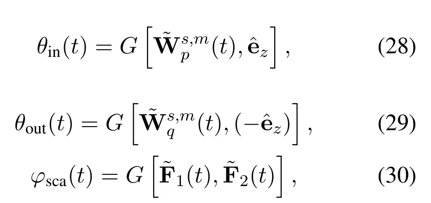
where the operationGdenotesG[W1,W2]=arccosrepresents the Frobenius norm.is the unit vector ofzaxis in LCSs,m.are the projections ofandonto thexOyplane in LCSs,m,respectively.After these three angles related to reflection and scattering on the surfaces of scatters are calculated,whether reflection or scattering occurs on the surfaces can be determined.
For double-bounce cases,the path gainad,m(t)can be calculated as

whereηT(t)andηR(t)are the diffuse scattering coefficients related toat the Tx side andat the Rx side,respectively.aspr(t)andama(t)can be obtained by replacing the length of LoS path in(18)-(19),WLoS(t),with the length of double-bounce path,Similar toη(t)in(21),ηT(t)andηR(t)can be calculated based on(22)-(26).In order to calculate the incident angles,elevation and azimuth angles of reflected ray onand,the vectors of incident and reflected rays need to be derived.

The vectors of incident and reflected rays related toandcan be transformed in LCS by(27).Based on similar calculations of(28)-(30),the incident angles,elevation and azimuth angles of scattered ray onandcan be obtained.Finally,the diffuse scattering coefficientηT(t)andηR(t),the path gainad,m(t)for the double-bounce can be calculated.
Some key parameters of the proposed channel model in this paper are summarized in Table 1 for easy reference.
III.CHANNEL PARAMETER UPDATE AND DYNAMIC CHANGES
3.1 Updating Channel Parameters
The movements of MS and/or clusters result in channel variance over time.Thus,the non-stationarities of the THz channel are considered in this proposed model.Within a certain period,the locations of clusters and/or MS are changing.Thus,the channel parameters,e.g.,distances between BS(or MS)and clusters,time delay,AoA,AoD,Doppler frequency,etc.,are time-variant as well.For single-bounce cases,the LoS vector from BS to MS at time instanttcan be calculated as

wheret0is the initial time instant andΔtis the minimum time interval for parameter update.Moreover,the ray vector from thepth Tx antenna element toSTs,mat time instantt(t=t0+Δt),is given by
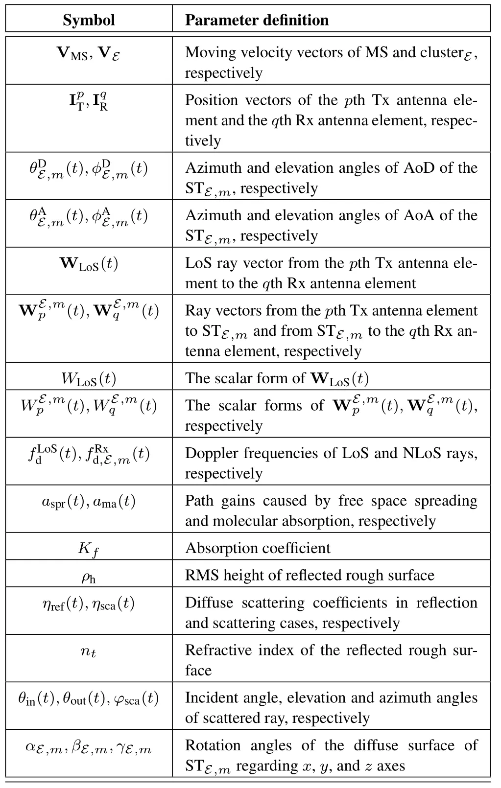
Table 1.Key parameters in the proposed channel model.

Similarly,due to the movements of MS and clusters,the ray vector from STs,mto theqth Rx antenna element at time instantt,is derived as

For double-bounce cases,the ray vectors fromfrom thepth Tx antenna element toand fromto theqth Rx antenna element,can be updated based on(32),(34),and(35),respectively.
Assuming that LCS orientations of reflection surfaces of scatterers remain unchanged during the movements of clusters.Since the positions of clusters and/or the MS change over time,the corresponding angular channel parameters vary as well.As a consequence,the incident and reflected angles on the rough surfaces need to be updated at the end of every time interval.The time-variant angles related to diffuse scattering,i.e.,θin(t),θout(t),andφsca(t),can be calculated based on(28)-(30).
Intuitively,with the movements of the MS and/or clusters,some clusters that contribute to the wireless links between Tx and Rx in the previous time interval will disappear.At that time,the rest of clusters will survive and some other new clusters will be generated.This time evolution process of channel properties can be represented as a birth-death process[36].LetλGandλRdenote the generation and recombination rates,respectively.It is assumed that the channel properties do not change during the minimum time intervalΔt.The probability of each cluster that can survive during the lastΔtis calculated by[37]

where Vmeandenotes the average velocity of all moving clusters.Pcmeans the proportion of moving clusters in total clusters.
3.2 Transition Between Reflection and Scattering During MS Movement
As the indoor surfaces are relatively rough for THz waves,the NLoS paths usually experience transition between reflection and scattering many times during the movement of MS.Therefore,the received power fluctuates as the Rx moves from one place to another.As shown in Figure 4,the THz signal is transmitted from Tx and diffusely scattered by indoor rough building surfaces,e.g.,walls,ceiling,and floors.Consequently,at a certain period,reflection and scattering will occur one after another on rough surfaces.
To illustrate how strong the fluctuation of NLoS path gain is during the movement of the MS,we need to calculate the path gains of reflection and scattering separately according to the conditions under which reflection and scattering occur.
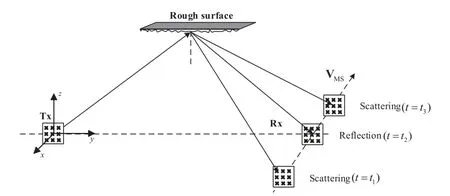
Figure 4.Illustration of transition between reflection and scattering during the MS movement.
Ifθin(t)=θout(t)andφsca(t)=0,then reflection occurs.The path gainAref(t)can be calculated as

Ifθin(t)/=θout(t)orφsca(t)/=0,then scattering occurs.The path gainAsca(t)can be calculated as

Here,the calculations of variables can be found in subsection 2.2.
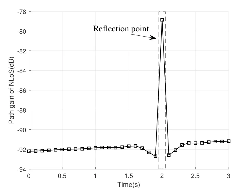
Figure 5.Transition process of NLoS path gain between reflection and scattering.
Figure 5 shows the transition of NLoS path gain between reflection and scattering during the movement of the MS.Here,the MS is in motion(VMS=0.5 m/s)and clusters are static for simplicity.The signal frequencyfis 650 GHz.The distance of NLoS path is about 7 m.As Figure 4 illustrated,in the movement process of Rx,reflection occurs at timet=t2.This process is visualized in Figure 5,where the reflection occurs att=2 s and scattering occupies the rest of the time.It is obvious that the reflection benefits a big increase of the path gain comparing with the scattering cases.
3.3 Dynamic Generation Procedure of the Channel Model
In summary,the time-varying channel impulse response can be dynamically generated based on the flowchart in Figure 6.
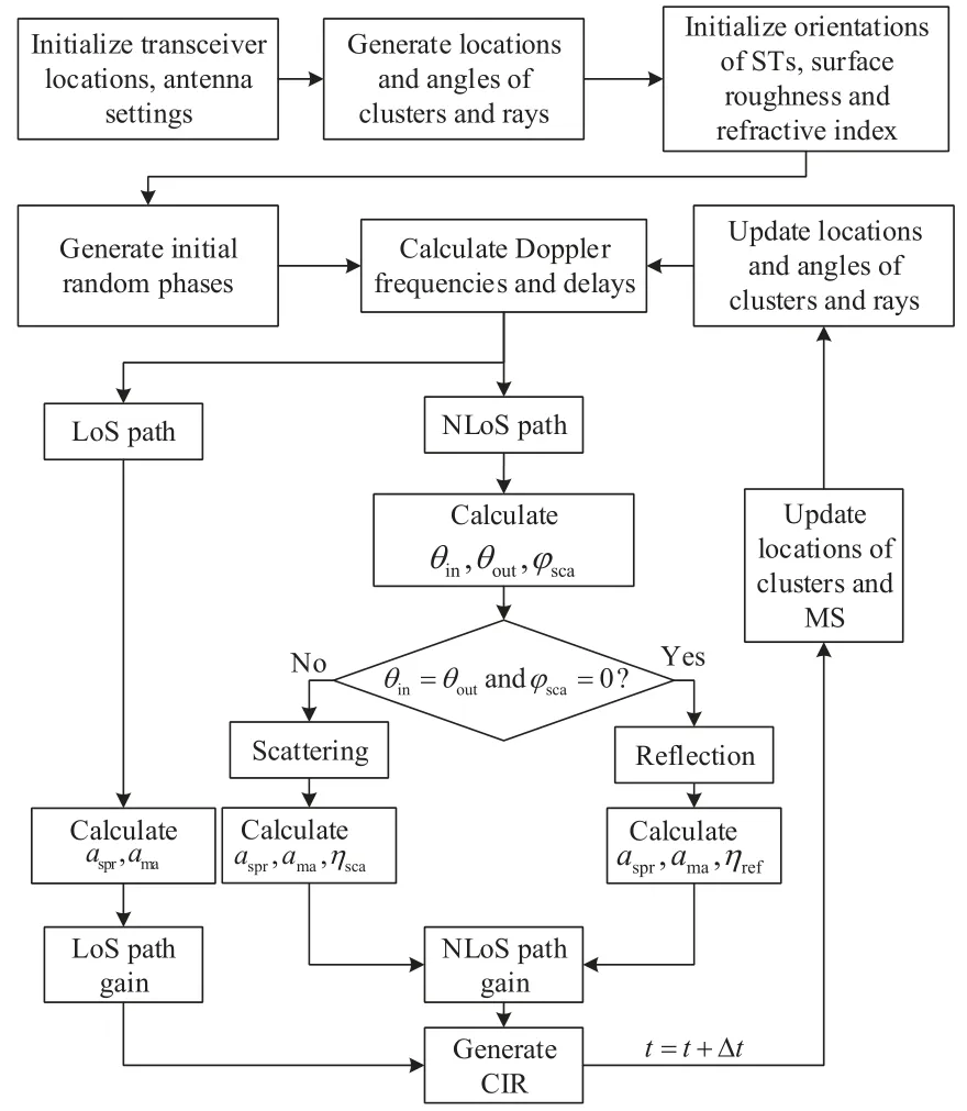
Figure 6.Flowchart for dynamically generating channel impulse response.
IV.STATISTICAL PROPERTIES
In this section,some typical statistical properties of the proposed 3-D hybrid dynamic channel model will be derived.
4.1 Cluster and Power Distributions in Delay and Space Domains
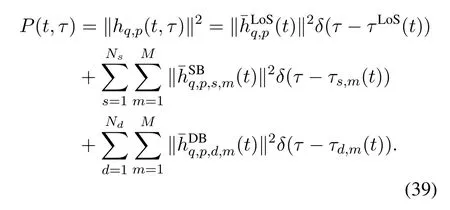
On one hand,PDP is an appropriate metric to characterize the multipath and power distributions of the propagation channel.Based on CIR function,PDP of the wireless channel between thepth Tx antenna element and theqth Rx antenna element can be obtained by
On the other hand,to illustrate the 3-D distributions of clusters and power in space domain,PAPs in the Tx side and Rx side can be presented.
4.2 RMS Delay Spread
The multipath power spreading of the wireless channel in the time domain is evaluated by RMS delay spread,τRMS,which is calculated as[38]


whereτiandPiare the delay and received power of theith ray,respectively.
4.3 Temporal Autocorrelation Function
As mentioned above,the proposed channel model considers the non-stationarities in the time domain.Temporal autocorrelation function(ACF)is an appropriate property to illustrate the non-stationarity characteristic of channels in the time domain.Before we calculate the ACF,channel transfer function(CTF),which is the Fourier transform of the CIR,is supposed to be obtained first as follows.
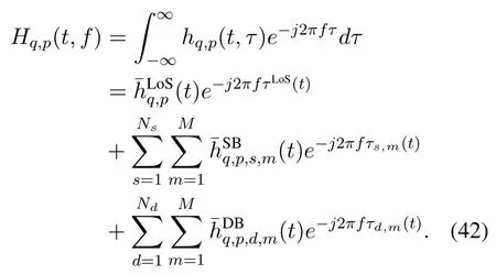
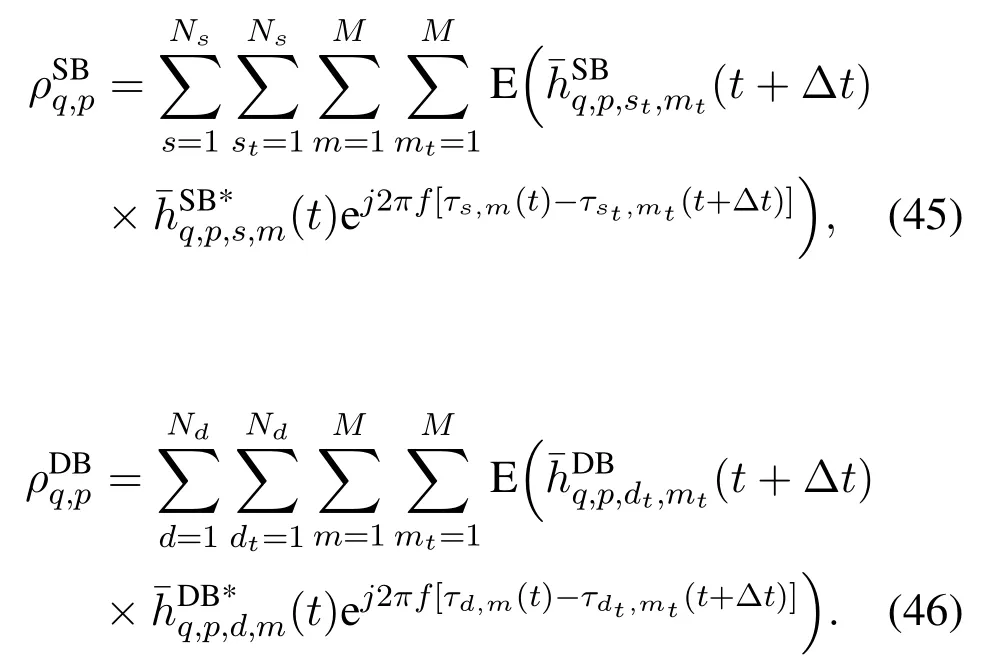
Since the parameters of LoS and NLoS rays are generated randomly,it is reasonable to assume that the LoS,single-bounce,and double-bounce components inHq,p(t,f)are uncorrelated.Therefore,the ACF can be calculated as

where(·)*denotes the conjugate of a function.Psurvis the survival probability of clusters when channel evolves fromtto(t+Δt).The autocorrelation of LoS ray,can be given by

Likewise,the correlation of single-bounce rays,and double-bounce rays,can be respectively given by
V.RESULTS AND ANALYSES
In this section,some statistical properties of the 3-D hybrid proposed THz channel model will be analyzed.Measured results in[18]and[28]will also be used to evaluate the correctness of the proposed model.Consider a typical indoor wireless propagation environment and let the distance between Tx and RxRLoS=5 m.The Tx and Rx are at the same height,which is 1.5 m.The number of clustersNis set as 4,and the number of rays in each cluster,M,is set as 20.Only a single polarization is considered for simplicity.The distance between clusterEand Tx,,follows an exponential distribution with a mean value of 3 m.Meanwhile,EAoD and AAoD follow wrapped Gaussian distributions,where the mean is set as 0 and the concentration factor is set as 4.Additionally,the EAoD and AAoD offsets of STE,m,,and,obey the Laplace distribution with location parameterμ=0° and scale parameterb=1°.As for molecular absorption,a typical gas mixture model with mean latitude in summer is selected as the wireless propagation environment.Then,the absorption coefficientKfcan be obtained from the HITRAN database[34].Additionally,we assume that the reflected surfaces in indoor scenarios are made of common plaster.Let the refractive index,nt,and RMS height of rough surface,ρh,are 2.2 and 0.15 mm,respectively.Besides,the moving speed of MS is set as 1 m/s.
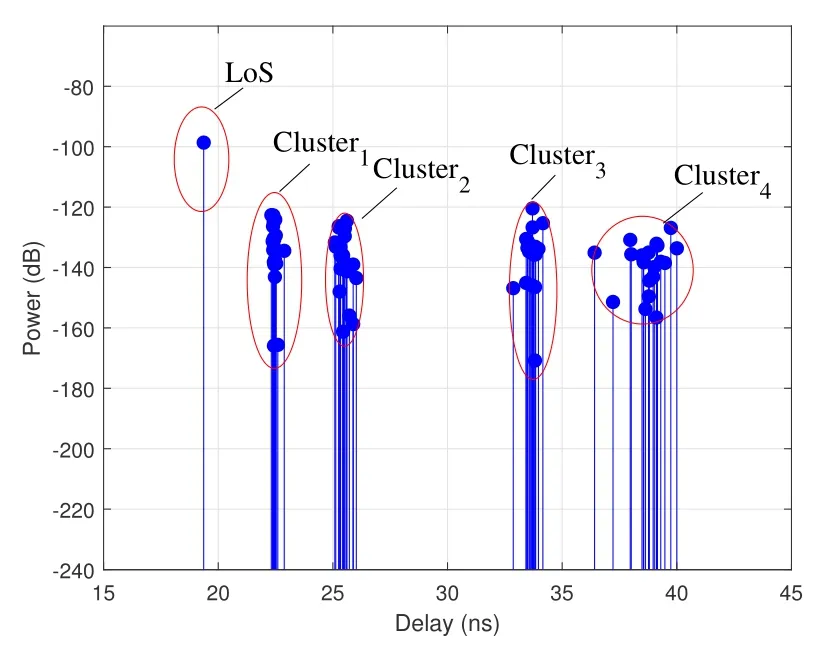
Figure 7.PDP of one realization.
Based on the proposed model,we can generate CIRs with the aforementioned parameters.The PDP of one realization is illustrated in Figure 7.Here,the frequencyf=350 GHz and molecular absorption coefficientKf=0.001 61 m-1.As Figure 7 shown,the power attenuation of the LoS ray is about 20 dB lower than that of the NLoS rays.Even in the same cluster,there is a great difference between power attenuation of rays.
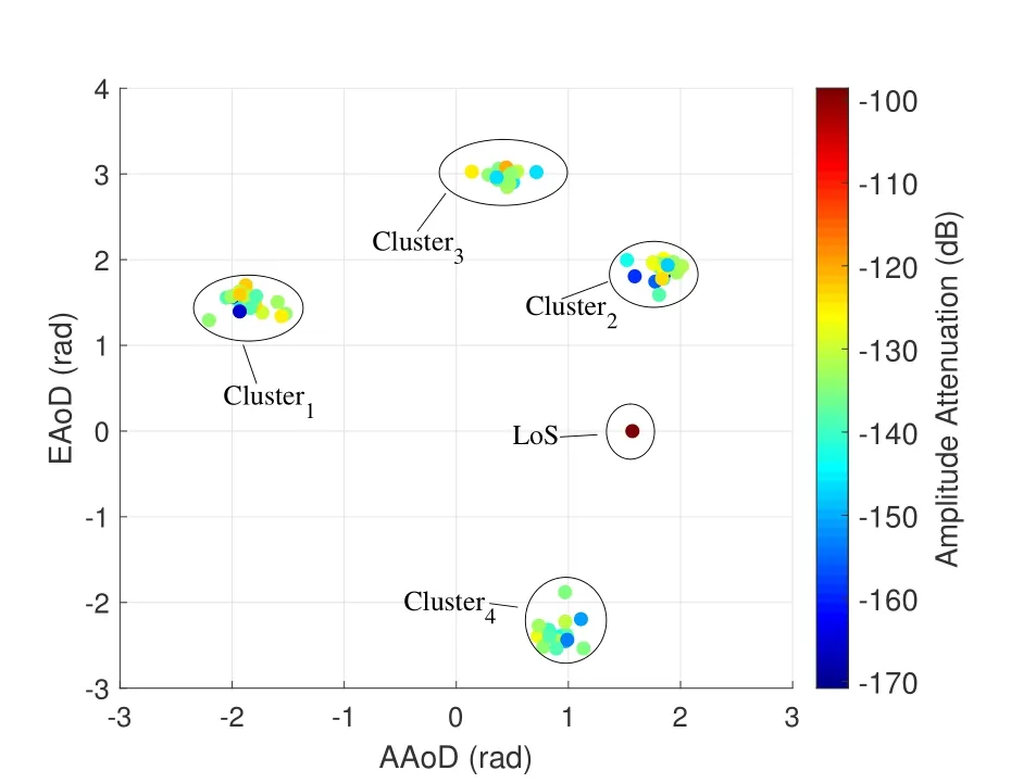
Figure 8.PAP of one realization at the BS side.
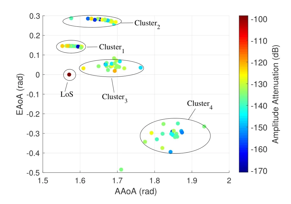
Figure 9.PAP of one realization at the MS side.
The PAPs of the same realization at both sides are illustrated in Figure 8 and Figure 9.Additionally,the clusters which correspond to those in Figure 7 and amplitude attenuation are presented in azimuth and elevation planes.
As the THz waves have high directionality,different Tx and Rx antenna beamwidths will influence the number of observable clusters for the transceivers and other channel characteristics.To demonstrate the impact of antenna beamwidth on the channel,the dependency of RMS delay spread on Tx and Rx antenna beamwidths is illustrated in Figure 10.The results are the average of 1000 Monte Carlo simulation results.
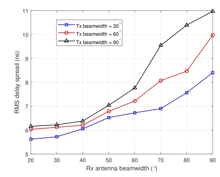
Figure 10.The dependency of RMS delay spread on Tx and Rx antenna beamwidths.
When the antenna beamwidth of Tx is fixed,the RMS delay spread of the channel rises with the increase of the beamwidth of Rx.Meanwhile,the RMS delay spread of the channel becomes larger when the Tx antenna beamwidth broadens.From the cluster point of view,the observable and effective clusters for the channel decrease when the antenna beamwidths of Tx and Rx become narrower.Consequently,the directionality of the THz waves inevitably leads to the sparsity of indoor THz channel.
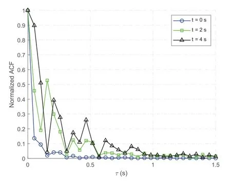
Figure 11.Normalized ACFs of the proposed channel model at different time instants(f=350 GHz).
Figure 11 depicts the normalized ACFs of the proposed channel model at different time instants.It is shown that the normalized ACFs at initial timet=0 s,t=2 s,andt=4 s are different,which proves that the proposed indoor THz channel is non-stationary in the time domain.
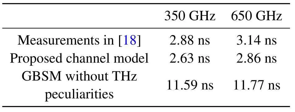
Table 2.Comparison of RMS delay spreads of the proposed model,measurements,and the GBSM without molecular absorption and diffuse scattering.
In order to verify the correctness of the proposed model,the RMS delay spread of the channel is simulated and compared with the measurement results from[18].The GBSM without molecular absorption and diffuse scattering is also considered.In the simulation,the frequencies,the layout of room,and the properties of the materials are the same as those in the measurements.According to the measured results,we also set the number of clusters,N,as 4.Moreover,the clusters and MS are set as static,which is consistent with the measurements.Based on the measured results of mean excess delay and path loss,the RMS delay spreads of 350 GHz and 650 GHz in the specific indoor channel are calculated and shown in Table 2.Besides,the RMS delay spreads of the proposed channel model and the GBSM are obtained by averaging 1000 Monte Carlo simulation results.As depicted in Table 2,the simulation results of the proposed model are close to the measurements.Without considering the molecular absorption and diffuse scattering,the RMS delay spread values are much larger than the measured results.Therefore,our proposed model is able to mimic the realistic channel well.Additionally,Figure 12 presents the probability density function(PDF)of the delay spread in indoor scenario,in which the channel parameters are the same as those in the simulation of Table 2.As Figure 12 illustrated,the simulation result of the distribution of delay spread can be approximated by the lognormal distribution with parametersμ=3.82 andσ=0.66.
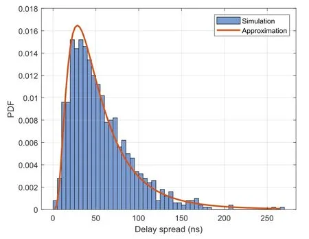
Figure 12.PDF of delay spread in indoor scenario of Table.2.
Furthermore,in order to evaluate the proposed channel model more comprehensively,the simulated channel characteristics are compared with another THz channel measurement in[28],where other channel properties like Ricean K-factor are measured apart from RMS delay spread.The channel simulation parameters are set as close as possible to the measurement scenario.As Figure 13 shown,K-factors and RMS delay spreads of the proposed model and the GBSM without THz peculiarities are simulated,respectively.Compared with the measured results,the root mean square error(RMSE)of K-factor of our proposed model is 4.9 dB,and that of the GBSM without THz peculiarities is 32.9 dB.Meanwhile,the RMSE of RMS delay spreads of the proposed model and GBSM without THz peculiarities are 3.0 ns and 7.2 ns,respectively.Therefore,it can be concluded that our proposed model can represent the realistic indoor THz channels more accurately than the GBSM without considering the characteristics of THz waves.
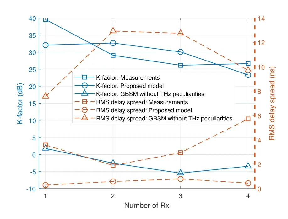
Figure 13.K-factors and RMS delay spreads of measurements in[28],our proposed channel model,and GBSM without molecular absorption and diffuse scattering(Solid lines represent K-factors,and dashed lines are RMS delay spreads).
VI.CONCLUSIONS
In this paper,we have proposed a 3-D dynamic channel model in the THz band by a hybrid modeling approach,which combines the deterministic and stochastic modeling methods.Three propagation mechanisms,namely,LoS,reflection,and scattering,have been considered.Each ray is investigated individually,taking into account molecular absorption and diffuse scattering of THz propagation.Moreover,the dynamic generation procedure of CIRs has been developed to mimic the non-stationarity of the channel.Furthermore,some statistical properties of the proposed channel have been derived and investigated.In addition,the K-factor and RMS delay spread values of the proposed 3-D dynamic channel model match the measured data well.To sum up,the proposed THz channel model can benefit the deployment and design of indoor wireless communication systems in the THz band.
ACKNOWLEDGEMENT
This work was supported by the National Key R&D Program of China under Grant 2020YFB1804901,the National Natural Science Foundation of China under Grant 61871035,and the National Defense Science and Technology Innovation Zone.
- China Communications的其它文章
- Towards 6G:Paradigm of Realistic Terahertz Channel Modeling
- Terahertz Wireless CommunicationS
- Channel Measurement and Path Loss Modeling from 220 GHz to 330 GHz for 6G Wireless Communications
- THz Channel Modeling:Consolidating the Road to THz Communications
- Wideband Channel Estimation for THz Massive MIMO
- Hybrid Precoding for Cluster-Based Multi-Carrier Beam Division Multiple Access in Terahertz Wireless Communications

