
Terahertz Orbital Angular Momentum:Generation,Detection and Communication
2021-05-28 00:04:38HangYangShilieZhengWeiHeXianbinYuXianminZhang
China Communications 2021年5期
Hang Yang,Shilie Zheng,*,Wei He,Xianbin Yu,Xianmin Zhang
1 College of Information Science and Electronic Engineering,Zhejiang University,Hangzhou 310027,China
2 Zhejiang Lab,Hangzhou 311121,China
Abstract:To accommodate the ever-increasing wireless capacity,the terahertz(THz)orbital angular momentum(OAM)beam that combines THz radiation and OAM technologies has attracted much attention recently,with contributing efforts to explore new dimensions in the THz region.In this paper,we provide an overview of the generation and detection techniques of THz-OAM beams,as well as their applications in communications.The principle and research status of typical generation and detection methods are surveyed,and the advantages and disadvantages of each method are summarized from a viewpoint of wireless communication.It is shown that developing novel THz components in generating,detecting and(de)multiplexing THz-OAM beams has become the key engine to drive this direction forward.Anyway,beneficial from the combination of infinite orthogonal modes and large bandwidth,THz-OAM beams will have great potential in delivering very large capacity in next generation wireless communications.
Keywords:terahertz vortex beam;orbital angular momentum;terahertz generation;terahertz detection
I.INTRODUCTION
Terahertz(THz),usually refers to the electromagnetic waves with the frequency of 0.1-10 THz,which is between the far-infrared(FIR)and microwave range[1].This frequency region is of great significance in the increasingly rare spectrum resources.Its rich spectrum can provide a foundation for the sixth generation(6G),virtual reality,autonomous vehicles and other emerging technologies[2-4].Moreover,as a transition region from the macro-electronics to micro-photonics,THz waves have a series of special properties.Firstly,THz waves have good penetrability for many materials such as wood,paper and plastic[5,6],and thus it can efficiently complement X-ray imaging and ultrasonic imaging technology.Secondly,the photon energy of THz waves is lower than the energy of most chemical bond,therefore,it will not damage the chemical structure of the tested material[7,8].Lastly,many material macromolecules have obvious absorption and resonance in the THz region,hence THz spectral imaging technology can distinguish the material composition and structure of object[9-12].
Since Allen et al.discovered that Laguerre-Gaussian beams can carry orbital angular momentum(OAM)in 1992[13],a lot of relevant studies have proved that X-ray,millimeter wave and other electromagnetic waves with different frequencies can also carry OAM[14,15].The OAM carrying beam has a helical wavefront,and a phase singularity in the center.Compared with the finite modes of SAM(generally including:linear polarization,left-handed polarization and right-handed polarization),the OAM can have infinite orthogonal modes in theoretical analysis[16].Hence,the OAM technology has good prospects in communication,imaging and other fields[17-19].
Since THz technology has a great potential in highspeed wireless communication providing large available bandwidth[20-22],while the use of OAM technology can also greatly increase the capacity of a communication system by multiplexing several orthogonal modes,which has already shown great superiority in both optical communications and wireless communications[23-25].Therefore,converging these two technologies,namely THz-OAM,is expected to be highly promising in future generation communication.Figure 1 shows the prospective application scenario of THz-OAM technology.In addition,THz-OAM technology has also been developed in some emerging fields,such as electron acceleration,highresolution terahertz imaging and quantum state manipulation[26-28].
In this review,we summary the research status of the THz-OAM beams and give a future vision of this new technology.In Section II and III,we discuss the typical methods for generating and detecting THz-OAM beams,respectively.In Section IV,we briefly review the current applications of THz-OAM beams in the communication field.And finally,a discussion and outlook are given in Section V.
II.GENERATION OF THZ-OAM BEAMS
2.1 Generation of THz Waves
The generation of THz is the basis for THz-OAM applications.The already reported methods for generating terahertz beams can be divided into three categories:ultrafast optoelectronics method,optical method and electronics method.
Transient current scheme and optical rectification scheme are belonging to the first category.In 1984,Auston et al.used the transient photocurrent on the surface of the photoconductive switch to generate a terahertz pulse[29],which represented the birth of terahertz optoelectronics.The transient current scheme uses the electric field of semiconductor surface to accelerate photon-generated carriers excited by femtosecond laser pulses to generate THz beams[30].The principle of the optical rectification method is based on the second-order nonlinear effect to generate terahertz pulses,which was first proposed by Auston and Winnewisser et al.[31,32].When an ultrashort laser pulse is radiated to a nonlinear medium(such as LiNbO3,ZnTe,DAST[33],etc.),if the phase matching condition is met,the THz beam would be generated by the nonlinear difference frequency effect.
The schemes based on optical method include the terahertz photoconductive antennas(THz-PCAs)scheme,quantum cascade laser(QCL)scheme and so on.The THz-PCAs scheme is currently widely used to generate THz continuous wave.The principle is that two continuous laser beams with a frequency difference in the range of THz are irradiated on the photoconductive antenna and mixed under the effect of the bias voltage,and a continuous terahertz wave is radiated[34-36].The QCL scheme is considered as a promising solution as it is based on semiconductor nanotechnology.The THz beams are generated by the energy level transition of the electron in the quantum well.
Gunn oscillators and terahertz multiplier are belonging to the last category.In 1963,J.B.Gunn discovered that GaAs samples would generate high-frequency oscillating currents in the negative resistance region,and thus Gunn oscillators was invented[37].The principle of THz multiplier is that the input signals are used as pump signal to generate the high-order harmonics in the range of THz through the nonlinear effect of Schottky diodes[38,39].
These methods of generating THz beams have their own characteristics,which should be taken into consideration for generating THz-OAM beams.Although the power of the THz beam generated by the ultrafast optoelectronics method is relatively small,the bandwidth is wide.The THz beam generated by the optical method has a large tunable frequency range and good coherence,but the devices are costly and have a short service life.The electronics method has the advantages of high signal power and easy integration,but it can only generate low frequency THz wave and have a small tunable range.
2.2 Generation of THz-OAM Beams
The OAM carrying beams are specially structured beams with helical wavefronts,which are also called vortex beams.The electric fields of the vortex beams in free space can be expressed as[40,41]
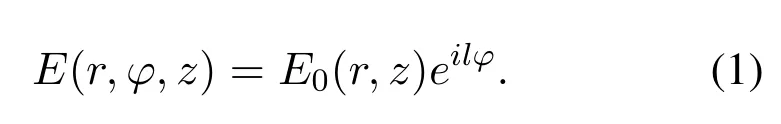

Figure 1.Prospective application scenario for THz-OAM communication system.
wherer,φandzare independent variables in cylindrical coordinates,respectively,andlis the OAM mode.Obviously the phase of the vortex beam changes with the azimuth angle,and the wavefront spirally rotates in the propagation direction,whose rotation degree and the direction are related to the magnitude and sign ofl.The characteristics of OAM carrying beams can be attributed to two points:the value oflis infinite in the real number space;the OAM modes with different integerslare mutually orthogonal[16].
Since the THz is between the radio and the optical frequency,the generation of THz-OAM can be inspired from those in both radio and optical region,yet it also has its own requirements.The uniform circular array is the most commonly used method for generating radio OAM beams owing to the simultaneous generation of multiple OAM beams and the flexibility of various antenna elements[42-44].However,limited by the accuracy of the commercial THz phase shifter,the structure is not optimal for the THz band temporarily.Using spatial light modulator(SLM)is also very often for generating optical OAM beams[45],however,the THz SLM is absent commercially.Currently the main generations of the THz OAM beams can be summarized as following.
2.2.1 Spiral phase plate-based method
The spiral phase plate(SPP)is the simplest and most direct structure to generate OAM beams.As shown in Figure 2,the SPP is composed of dielectric material,and its thickness is related to the azimuthφ.The relationship between the thickness andφcan be expressed as:
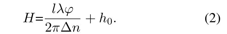
whereHis the thickness of SPP,h0is a constant,Δnis the difference between the refractive index of the dielectric material and environment.Owing to the difference in the optical path,using the SPP an incident plane wave can be transformed into an OAM carrying beam.In 1994,M.W.Beijersbergen et al.generated the OAM beam in the visible light[46],and later the OAM beam in the millimeter wave is also generated[47].However,limited by the development of THz technology,it was not until 2014 that Peter Schemmel et al.made SPPs in the THz region.The SPP is made of polypropylene and can generate THz-OAM beams with modes of±1 and±10 at 0.1 THz[48,49].In the same year,K.Miyamoto et al.used the nonlinear effect of DAST crystal to convert infrared light pulses into THz pulses with a frequency range of 2-10 THz.After the THz pulse passes through the SPP composed of Tsurupica olefin polymer,the THz-OAM beams with the modes of±1 at 2 THz and the modes of±2 at 4 THz are generated[50].In 2016,Yan Zhang et al.used 3D printing technology to produce a SPP made of polylactic acid materials that can work at 0.62 THz.In addition,they further studied the characteristics of THz-OAM beams under the different polarizations with the THz quarter-waveplate[51].
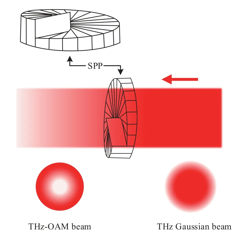
Figure 2.The process of generating THz-OAM beam by SPP-based method.
The SPP can not only generate OAM beams with a single mode,but also generate the OAM beams with several superimposed modes simultaneously.In 2015,Jian Wang et al.used 3D printing technology to produce a SPP made of Durus White RGD430 material that can work at 0.1 THz[52].And on this basis,they further proposed the pattern search assisted iterative algorithm to design the OAM broadcast plate[53].When the THz plane wave passes through the OAM broad plate,it can simultaneously generate THz-OAM beams with modes of 2 and 5.
Compared with that in the optical region,the THz SPP does not require high processing accuracy,and the existing 3D printing technology and mechanical processing can adequately meet the accuracy requirements.Thus,it is a simple method to generate THz-OAM beams.However,the varying thickness of the SPP would cause the problem of uneven amplitude of the THz-OAM beams due to the absorption and reflection coefficient of the material.Moreover,the SPP can only generate OAM beam at a specific wavelength,thus it is unable to work in broadband.
2.2.2 Metasurface-based method
The metamaterials which are composed of subwavelength periodic unit,emerged at the end of the last century[54,55].Through reasonably changing the shapes,physical sizes and arrangements of metamaterials,the metamaterials can obtain the supernormal physical properties that traditional materials do not have[56,57].With the development of the research on metamaterials,it is found that the three-dimensional devices composed of metamaterials are not only difficult to process,but also have a great insertion loss.Thus,a new structure,namely metasurface,was proposed[58].The metasurface is a two-dimensional structure composed of subwavelength periodic units with one or several layers.Due to its ultra-thin characteristic,it can reduce the volume and insertion loss,simultaneously[59].When electromagnetic waves pass through the metasurface,due to resonance,coupling and other factors,it would produce abrupt changes in some parameters such as phase or amplitude[60-62].Therefore,metasurface can be designed to manipulate polarization,phase,amplitude and other important parameters.
Fermat’s principle is usual used to theoretically analyze the manipulation of metasurfaces on the electromagnetic waves propagations.In general,the reflection law and the refraction law are established under the condition that the phase of electromagnetic wave changes continuously between two different media.Differently,the metasurface would introduce a phase mutation at the junction of the two mediums.As shown in Figure 3,the phase mutation introduced by the metasurface will create anomalously refracted and reflected beams[63-65].By changing the phase mutation reasonably,the propagation directions of anomalously refracted and reflected beams can be manipulated.
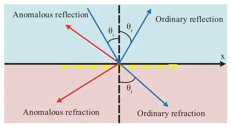
Figure 3.Schematic propagation of light beam in two different mediums.

Figure 4.The metasurface-pattern of V-shaped units and the experimental results.(a)the structure of V-shaped unit;(b)metasurface-pattern;(c)the interference pattern created by the interference of the OAM beam and a co-propagating Gaussian beam[63].
The THz-OAM beams could be generated by the anomalous refraction of metasurface.In 2011,Nanfang Yu et al.first combined the metasurface with OAM technology to generate OAM beams in the mid-infrared frequency range by using the V-shaped periodic units[63].As shown in Figure 4(a),the Vshaped periodic unit is composed of two gold arms.The incident electromagnetic wave will cause the resonance of the unit,thereby forming a surface current of the unit and radiating electromagnetic wave outward.By reasonably adjusting the angle of the symmetry axis and the angle between the two arms,the phase of the anomalously refracted beam could be manipulated within the range of 0 to 2π.Using this V-shaped periodic unit,a metasurface-pattern can be obtained according to the desired phase distribution,and Figure 4(b)shows the metasurface-pattern with the OAM mode of 1.From Figure 4(c),the OAM beam with a spiral phase is generated.
In 2013,Yan Zhang et al.proposed the V-shaped periodic units that can work in the THz region,and generated an OAM beam with thel=1 at 0.75 THz[66].Since then,many metasurface units working in the microwave or optical region,such as C-shaped unit,cross-shaped unit,and other periodic units have been proposed their corresponding units in the THz region[67-71].
THz-OAM beams can also be generated by anomalously reflected beams.In 2016,Jun-Fa Mao et al.proposed a scheme for generating THz-OAM beams based on the reflective metasurface,and it can transform the reflected beam into an OAM carrying beam,as shown in Figure 5(c).As shown in Figure 5(a),the graphene reflective unit consists of a graphene patch,an alumina layer,a polycrystalline silicon layer,a quartz layer and a platinum layer from top to bottom.A DC voltage is applied between the graphene patch and the polycrystalline silicon layer to change the chemical potential of the unit.The quartz layer is applied as the substrate of the unit,and it is grounded through the platinum layer[72-74].The phase of the anomalously reflected beam could be manipulated in the range of 0 to 2πby adjusting the size of the graphene patch and the bias DC voltage[74].As shown in Figure 5(b),after arranging the size of each unit,the metasurface can generate several OAM beams with different modes at 1.6 THz by changing the bias voltage.
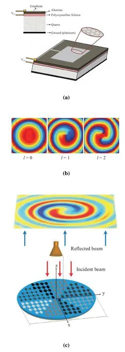
Figure 5.The reconfigurable reflective graphene metasurface and the simulation results.(a)graphene reflective unit;(b)simulated phase fronts of the OAM beams with the modes of 0,1 and 2;(c)reconfigurable reflective graphene metasurface where different colors correspond to different reflective phases[73,74].
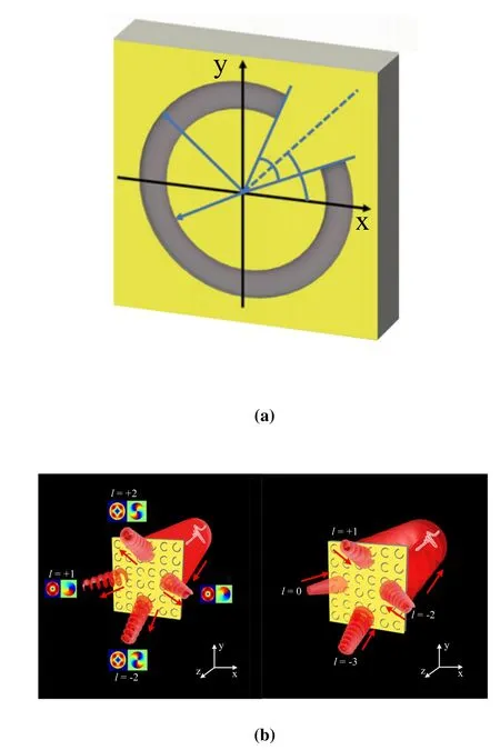
Figure 6.The schematics of C-shaped metasurface and the experimental results.(a)the structure of C-shaped unit;(b)schematics of OAM multiplexing and demultiplexing[69].
Since each unit could be manipulated,the metasurface has great scalability.In 2017,Yan Zhang et al.proposed a metasurface that works in the THz region and could simultaneously multiplex and demultiplex OAM beams[69].The periodic unit of the metasurface is shown in Figure 6(a).The unit is composed of a C-shaped slot on a gold sheet and a high resistivity silicon substrate,which works at 0.8 THz.Similar to the V-shaped unit,the C-shaped unit also manipulates the phase shift of the anomalously refracted beam by changing the angle of the symmetry axis and the opening angle of the split.The metasurface is composed of 100×100 units,and it has four different phase distributions.Each phase distribution is composed of a unique OAM phase and a unique tilt phase in four different directions(±x and±y directions).According to the Fourier optics,the tilted wavefront can shift the focus of metasurface.Therefore,the centers of the four different OAM beams would deviate from the coordinate origin and propagate in four different directions,as shown in Figure 6(b).Similarly,the metasurface can also demultiplex four individual OAM beams incident from four different directions into a beam for coaxial propagation.In 2020,Shi-Wei Qu et al.proposed an OAM mode-reconfigurable device,operating at 0.3 THz[75].The device is composed of two types of periodic units:height-variable unit[76-79]and transverse-variable unit[80,81],as shown in Figure 7(a).A phase shift can be achieved through changing heighthof the height-variable unit and widthwof the transverse-variable unit.Based on the two types of periodic units,they proposed the upper discrete dielectric lens and the lower discrete dielectric lens.Both lenses have a special phase distribution and are arranged in the propagation direction.By physically rotating the upper lens,the reconfiguration of five OAM modes from-2 to 2 could be achieved,as shown in Figure 7(b).
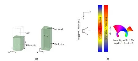
Figure 7.Architecture of the dielectric pixel element and schematic of the setup(a)height-variable unit and transversevariable unit;(b)schematic of the OAM reconfiguration[75].
Compared with the SPP method,the metasurface method can simultaneously generate the OAM beams with multiple modes at a wide frequency range.Besides,some special phase distributions(tilted phase,etc.)can control the propagation directions of the generated THz-OAM beams,which provides a basis for OAM multiplexing and demultiplexing.The current limitation of this method is lack of a general metasurface for various applications at various frequencies[82].Fortunately,selecting the optimal meta-units according to different situations would help improve the performance of the metasurface.The choice of metaunits needs to be considered comprehensively.Firstly,the meta-unit used in the OAM generation is to provide various phase shift,hence the meta-unit which can have the phase shift in the range of 0-360°at the desired frequency is the most important.Secondly,the size of the meta-unit should be considered.The smaller elements can not only improve the phase resolution of metasurface,but also improve the integration of entire system.Lastly,the insertion loss of the metaunits is an important parameter.In order to ensure the generated beams with a uniform amplitude and high gain,the insertion loss of the meta-units forming a metasurface should be small and close.
2.2.3 Holographic method
In 1948,Gabor discovered that if a light wave is diffracted or scattered by an object,the amplitude and the phase of the diffracted or scattered wave could be recorded by using a reference light wave coherent with the object light.Then,the image of the original object can be recovered through the interference fringes of the corresponding object and reference light[83].He named these interference fringes hologram,which means a picture that contains all information of the object.As shown in Figure 8,the holographic method includes two parts:wavefront recording and wavefront reconstruction.When object beamE(r,φ,z)and reference beamR(r,φ,z)interfere,the interference beam intensity can be expressed as:
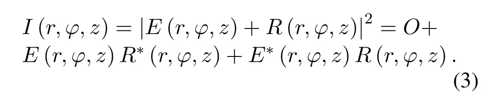
whereOis the sum of the intensity of the reference beam and object beam.It can be seen that the latter two terms are related to the phase and amplitude of the object beam and the reference beam.The hologram could be obtained by recording the interference beams with the medium,and it could be regarded as a complex grating that records the amplitude and phase of the object beam.For simplicity,the response of medium to interference beams could be regard as a linear function.
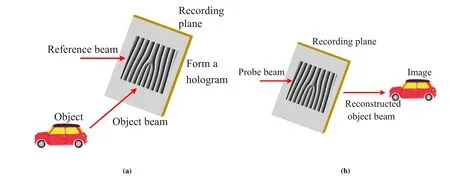
Figure 8.Holographic method.(a)wavefront recording;(b)wavefront reconstruction.
The wavefront reconstruction is achieved by illuminating the hologram with a coherent probe beam.When a coherent beam illuminates the hologram,the interference fringes in the hologram could be regarded as the wavefront modulation function.The field of the coherent probe beam passing through the hologram can be expressed as:
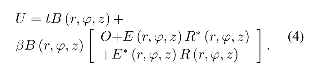
wheretis a constant,βis the response coefficient of recording medium,B(r,φ,z)is the complex amplitude of coherent probe beam.When the phase and amplitude of the probe light are consistent with the reference light,the third term of Eq.(4)is the reconstructed object beam.
However,the recording process of optical holography is complicated and requires an ideal experiment environment.In 1967,Lahmann et al.proposed the computational holograms[84-86],which do not require the existence of actual objects.According to the mathematical expression of interference beams,the computer can generate the computational hologram.With the development of computer technology and SLM,computational holograms could be loaded on the SLM for wavefront reconstruction.This technology greatly simplifies the process of generating holograms and makes the application of holographic technology more widely.
Optical OAM could be generated by loading computational holograms on the SLM[87,88].With the rise of THz technology,computational holography technology can also be used to generate THz-OAM beams.In 2013,Yan Zhang et al.proposed a spatial THz modulator based on the computational holography technology and generated several different OAM modes at the 1 THz[89].They illuminated the OAM interference light beam generated by computational hologram onto the silicon chip to form a photo-generated carrier distribution consistent with the holographic pattern.The THz-OAM beam is generated after the Gaussian THz beam passing through the medium silicon chip.In 2015,B.A.Knyazev et al.produced some diffractive Fresnel spiral phase plate by writing the computed holograms into the silicon chip.Then they generated non-diffracted THz beams with different modes through these plates at the wavelength of 141 μm[90].
The holographic method is a widely used method for generating OAM beams in the optical region.However,due to the lack of a corresponding mature spatial modulator in the THz region,the complex generation processes of the THz holograms greatly increase the complexity of the entire system.
2.2.4 Q-plate based method
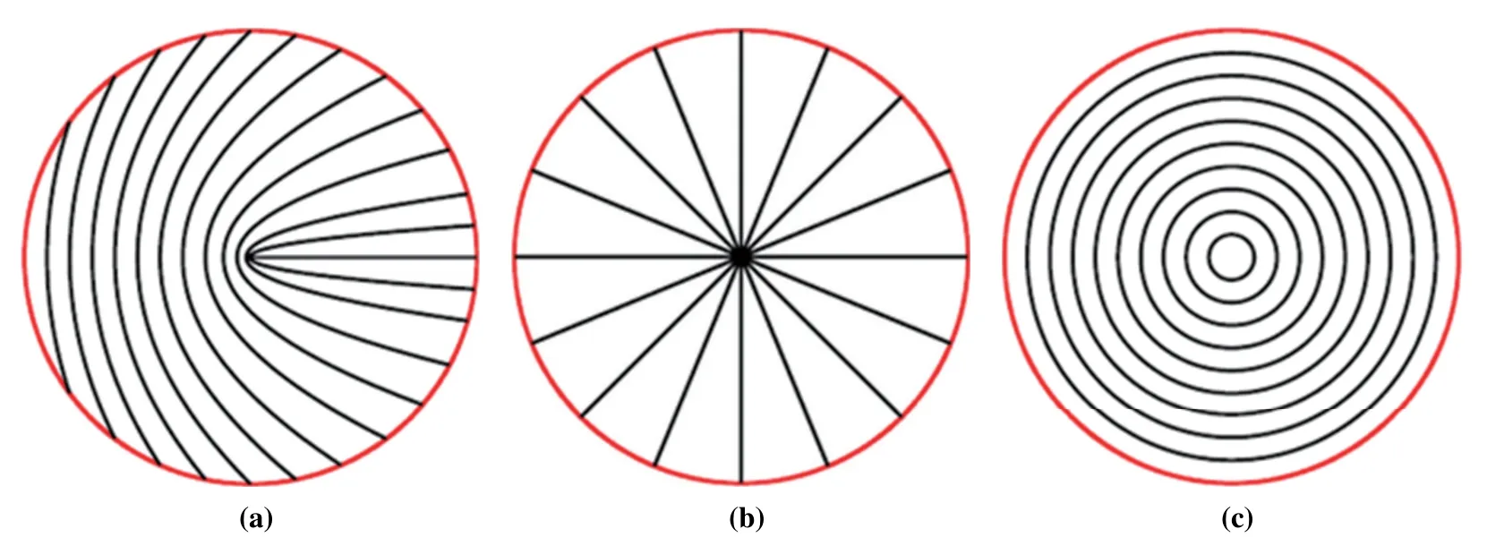
Figure 9.The optical axis distribution corresponding to different q and α0.(a)q=0.5,α0=0;(b)q=1,α0=0;(c)q=1,α0=π/2[91].
The q-plate is a geometric phase optical element,and its geometric phase is related to the geometric characteristics of optical axis distribution[92].It was proposed in 2006 and can realize the mutual conversion between the SAM and OAM of the optical beams[91].The q-plate is a kind of wave plate with non-uniform optical axis distribution at the transverse plane.The relationship between the orientation angleαof the optical axis and the azimuth angleφin the x-y plane can be expressed as[92]

whereqis the topological charge of q-plate,α0is the initial angle between the optical axis and the x-axis.As shown in Figure 9,when the topological charge and the initial angle take different values,the optical axis distribution of the q-plate would change accordingly.These q-plates would modulate the phase,polarization and amplitude of the incident light beams.The interaction between the SAM and OAM of the light beams in the q-plate could be calculated and analyzed by the Jones matrix,and it can be express as
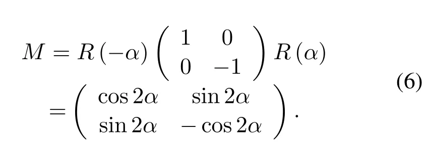
whereR(α)is the standard 2×2 rotation matrix by angleα.The left-circular polarized and right-circular polarized plane waves can generate the OAM beams with different modes after passing through the qplate.When left-circular polarized plane wave passes through the q-plate,the electric field of the outgoing wave can be expressed as
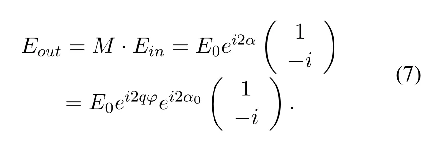
whereE0is the amplitude of incident beam.It can be seen that the polarization of the optical beam has changed from the initial left-circular polarization to the right-circular polarization,and it has also acquired a phase factorei2qφ.Whenqis an integer or a semiinteger,the outgoing wave is an OAM beam with a single mode.Obviously,when the incident wave is a right-circular polarized plane wave,the sign of the outgoing OAM waves mode is inverted.
As an emerging optical element,the q-plate has been used to generate optical OAM beams because of its characteristics of beam shaping and wavefront control[94-96].In recent years,the q-plates that can work in the range of THz have also been proposed and used for THz-OAM beams generation.In 2014,Kuwata-Gonokami et al.combined the THz q-plate with the quarter-wave plate to generate a broadband THz beam in the range of 0.75-2 THz[93,97].As shown in Figure 10,the q-plate is composed of eight GaP crystal sectors,each one with a different orientation of optical axis.When an infrared pulse radiates on the q-plate,it would generate a THz pulse due to the optical rectification effect of GaP crystal,and the polarization direction of the THz pulse is related to the GaP optical axis.Therefore,a horizontally polarized infrared pulse illuminates on the q-plate would generate a THz pulse beam with the radially distributed polarization.When the radially polarized beam passes through a quarterwave plate whose fast axis is parallel to the x axis,the electric field of the outgoing beam can be expressed as
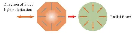
Figure 10.Generation process of radial beam[93].
whereLis the azimuthal order of the radially polarized beam,theE(r,z)is the electric field component independent of azimuthφ.After passing through a polarizer whose transmission axis is 45°from the x axis,the THz beam with OAM phase factoreiLφis generated.
As a material widely used in the visible light range,the liquid crystal has great application potential in the THz region.Moreover,the liquid crystal has been proved to be a material that can be adjusted by temperature,external electric field and other methods in the THz region[98-101].Thus,the q-plate consisting of liquid crystal can generate broadband THz-OAM beams with different modes according to the different application scenarios.In 2017,Yanqing Lu et al.proposed the q-plate consisted of liquid crystals,and generated OAM beams with modes of 1 and 4 at 1 THz[102].In addition,they also proved through experiments that the applied voltage could control the phase shift of the liquid crystal in the range of 0.5 to 2.5 THz,which creates a foundation for arbitrary and instant manipulation of THz-OAM mode.
As an emerging optical component,q-plate provides a new idea for generating THz-OAM beams.Due to the tunability of the liquid crystal,the q-plate method can manipulate the THz-OAM beam arbitrarily in real time.However,due to the strict requirements for input beam,the further expansion of the q-plate method is limited.
III.DETECTION OF THZ-OAM BEAMS
3.1 Detection of THz Waves
After accurately detecting the amplitude,phase and other parameters of THz beams,the various applications based on THz technology could be realized.Therefore,the detection of THz waves is as same important as the generation.The proposed methods for detecting THz beams can be divided into two categories:photodetection method,and electronic detection method[103].
The photodetection method detects the THz signals through optical beams,and it includes the photoconductive antenna scheme,the electro-optical crystal scheme and other schemes.The photoconductive antenna consists of two parallel electrodes plated on a semiconductor substrate[104-106].When the pulsed optical beam illuminates on the photoconductive antenna,a large number of free carries would be generated.The THz field could be approximately regarded as a constant electric field when the lifetimes of free carriers are much shorter than the pulse period of THz.Thus,the free carriers would directionally move to generate current,and the information of the THz waves could be obtained by detecting the current.
The electro-optic crystal scheme uses the Pockels effect.When a linearly polarized light passes through the electro-optic crystal under this THz field,the light would become elliptically polarized as the external THz field has different effects for the refractive indices of ordinary light and extraordinary light.Consequently,the information of THz pulse could be reflected when detecting the difference of ordinary light and extraordinary light[32].
Figure 11.Detection process of direct detection scheme.
The photoconductive antenna scheme and electrooptical crystal scheme have a similar principle for detecting THz signals,but they also have their own characteristics.For the low frequency THz signals,the photoconductive antenna scheme has a higher signalto-noise ratio;for the high frequency THz signals,the electro-optical crystal scheme has higher sensitivity.
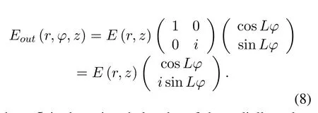
The direct detection scheme and heterodyne detection scheme belong to the electronic detection method.As shown in Figure 11,the direct detection scheme detects the amplitude of the THz beams.Both the THz signal beamWSand the background noiseWBare focused on the detector by the focusing lens to cause the change of the electrical signal,which passes through the amplifier to generate the current signalIS.The detectors used in the direct detection scheme mainly include:bolometer,Golay detector and Schottky diode,etc.[107-113].Among them,the low-temperature bolometers have the highest sensitivity with noise equivalent power(NEP)up to~(0.4-3)×10-19W/Hz1/2at operation temperature~100-300mK[103].
The heterodyne detection scheme down-converts THz signal into a signal with low frequency,so it can simultaneously detect the amplitude and phase of the THz signal.As shown in Figure 12,the THz signalWSand the local oscillation signalWOare injected into the mixer to extract the frequency difference.The information of the THz signal could be obtained after the generated intermediate frequency signalWIFfiltered.As the core element of the heterodyne detection scheme,the mixer usually uses electronic devices with strong second-order nonlinearity,such as Schottky Barrier Diode,Superconductor-Insulator-Superconductor tunnel junction,Superlattice mixer and other devices[114-116].
The direct detection scheme can detect THz signal with a wide frequency range with high sensitivity.However,the direct detection scheme has a smaller spectral resolution because it is easily affected by the background environment.Compared to direct detection scheme,the heterodyne detection scheme can detect frequency modulation and phase modulation,and the IF conversion process cam provide extra signal gain.Yet,limited by the existing mixer,the heterodyne detection scheme is not easy to integrate and cannot work at high frequencies[103].
3.2 Detection of THz-OAM Beams
The detection process of THz-OAM beams can be divided into two parts:the demodulation of THz-OAM beams and the detection of the demodulated THz-OAM beams.Currently,the key of the application of THz-OAM technology in practice is how to separate and detect OAM beams carrying different modes efficiently and accurately.
3.2.1 Reverse spiral phase plate and plane wave interference method
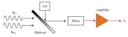
Figure 12.Detection process of heterodyne detection scheme.
Similar to the generation of the THz-OAM beams,the SPP is also the simplest component to detect and transform THz-OAM beam.It can be seen from Eq.(2)that for an OAM beam with the mode ofl,using a dielectric plate with the thickness ofcan eliminate its spiral phase factor and transform it into a Gaussian beam.Since the mode of the demodulated SPP is opposite to the mode of the OAM beam,it is called the reverse spiral phase plate.
In 2014,Kejia Wang et al.used a reverse SPP to demodulate the OAM beams at 0.1 THz[117].They used a THz beam splitter to split the THz plane wave into two beams,and the two beams are modulated by two SPPs with modes of 2 and 5,respectively.The other THz beam splitter combines the two modulated beams to generate an OAM beam with two modes.Then,they used the SPPs with modes of-1 to-6 to demodulate the superimposed beam,and the Schottky diode was used to detect the intensity of the demodulated beam.In the experimental results,the bright spot appears in the center of the demodulated beams when using the spiral phase plates with modes of-2 and-5.In 2015,Jian Wang et al.used the same method to detect the OAM beams with several modes generated by the broadcast plate[52].
However,the method of using SPP to detect OAM beams has obvious shortcomings.A specific SPP can only demodulate the OAM beam with a specific mode at a specific frequency.When detecting the OAM beams with multiple modes,different SPPs need to be replaced,hence the method lacks scalability and flexibility in the communication field.
Plane wave interference is a method that can detect the modes of the OAM beams intuitively.The interferogram,which is usually called fork pattern,could be obtained by interfering an inclined reference plane wave with an OAM beam.The mode of a OAM beam could be detected by analyzing the shape of the fork pattern[118-120].As shown in Figure 13,when the mode of the OAM beam isl,the center fringe of the fork pattern would becomel+1.Moreover,the forks directions are related to the signs of OAM beams modes.Therefore,the fork pattern can intuitively show the modes of OAM beams.
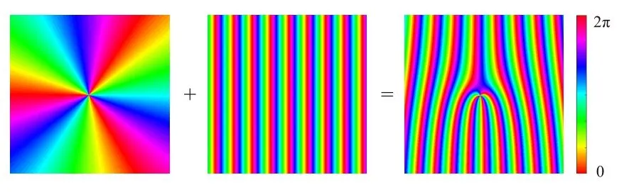
Figure 13.Interference of the OAM beam with l=3 and inclined plane wave.
In 2015,Jinsong Liu et al.detected the modes of several different OAM beams by plane wave interference method at 0.3 THz[121].They combined the SPP with the axicon and proposed the helical axicon.The helical axicon is produced by 3D printing technology,and it can transform a Gaussian beam into an OAM beam with nondiffraction property.In their experiment setup,the silicon wafer divides the THz Gaussian beam generated by Gunn diode into two parts.One part forms an OAM beam after passing through a helical axicon,and the other part forms an inclined reference beam after being reflected by a mirror.The fork pattern formed by the reference beam and the OAM beam is detected by a Schottky diode.It can be seen from the experimental results that the plane wave interference method successfully detected the mode of THz-OAM beam.In 2017,the same method was used by Kejia Wang et al.to detect the OAM beams generated by the diffractive phase plate at 0.3 THz[122].
The plane wave interference method can intuitively distinguish OAM beams with a single mode.However,it cannot distinguish the OAM beams with several different modes,nor can it transform the OAM beams into Gaussian beams.Thus,it is hard to be used in high-speed communication applications.
3.2.2 Coordinate transformation method
The coordinate transformation method is a method based on optics for separating and detecting the OAM beams with different modes.The core of the coordinate transformation method is to transform the OAM beam from a coordinate to another coordinate.The coordinate transformation method firstly uses a refraction device to transform an OAM beam with an angular phase gradient into a beam with a phase gradient along a straight line.Then,it would use a focusing lens to turn the beam with a straight phase gradient into a focused spot.
The process of coordinate transformation is shown in Figure 14.The device for realizing coordinate transformation consists of two elements:R1andR2.It can realize the mapping of the coordinate(x,y)in the input plane to the coordinates(u,v)in the output plane,whereu=andv=aarctan(y/x).The parametersaandbare used to adjust the coordinate transformation process.The phase profile of the first elementR1can be expressed as[123-125]
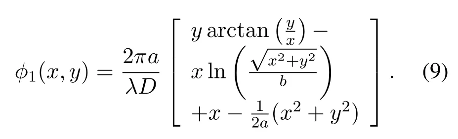
whereDis the distance between the two elements,the parametera=d/2πensures the transformed beam is fully mapped on width ofd.In order to avoid the diffraction effect at the edge of the elementR2,the value of widthdshould be smaller than the width of the elementR2.The selection of parameterbis independent ofa,and it determines the position of the transformed beam in theudirection.The phase profile of the second elementR2can be expressed as
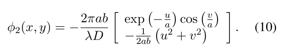
The elementR2compensates the phase aberration introduced by the coordinate transformation,and its phase distribution is calculated by stationary phase approximation[126,127].After the THz-OAM beam passing through elementR1and elementR2successively,it would be focused by a lens with focal lengthf.The relationship between the position of the focused spot and the mode of the OAM beam can be expressed as
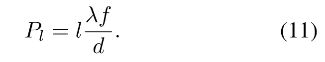
It can be seen that the OAM beams with different modes would be focused on the different positions,accordingly,the coordinate transformation method realizes the separation of the OAM beams with multiple different modes.
The coordinate transformation method is a method that has been proposed in recent years and can effectively separate and detect OAM beams.In 1974,Olof Bryngdahl firstly proposed the concept of coordinate transformation in an article about optical image processing[129].In 1987,W.J.Hossack et al.realized the transformation from Cartesian coordinate system to a logarithmic polar coordinate system based on computational hologram[127].In 2010,Gregorius C.G.Berkhout et al.applied the coordinate transformation method to detect the mode of the optical OAM beam,and they realized the efficient separation and detection of the OAM beams with different modes[126].In their experiment setup,the coordinate transformation of the optical beam is realized by SLM.However,due to the low diffraction efficiency of the SLM,the great spatial link loss limits the application range of this method.In 2012,Martin P.J.Lavery et al.proposed the refractive elements instead of SLM to achieve the coordinate transformation of optical beams[130].The refractive elements are made of poly methyl methacrylate by mechanical processing,and it can significantly shorten the spatial optical path and reduce the link loss.Thus,the coordinate transformation method can detect the OAM beams with lower power.In 2014,Yan Yan et al.applied the coordinate transformation to the microwave frequency range[131].The efficient separation and detection of multiple different modes in the microwave OAM beam are realized by refractive elements,and they have been successfully applied in actual microwave communication experiments.
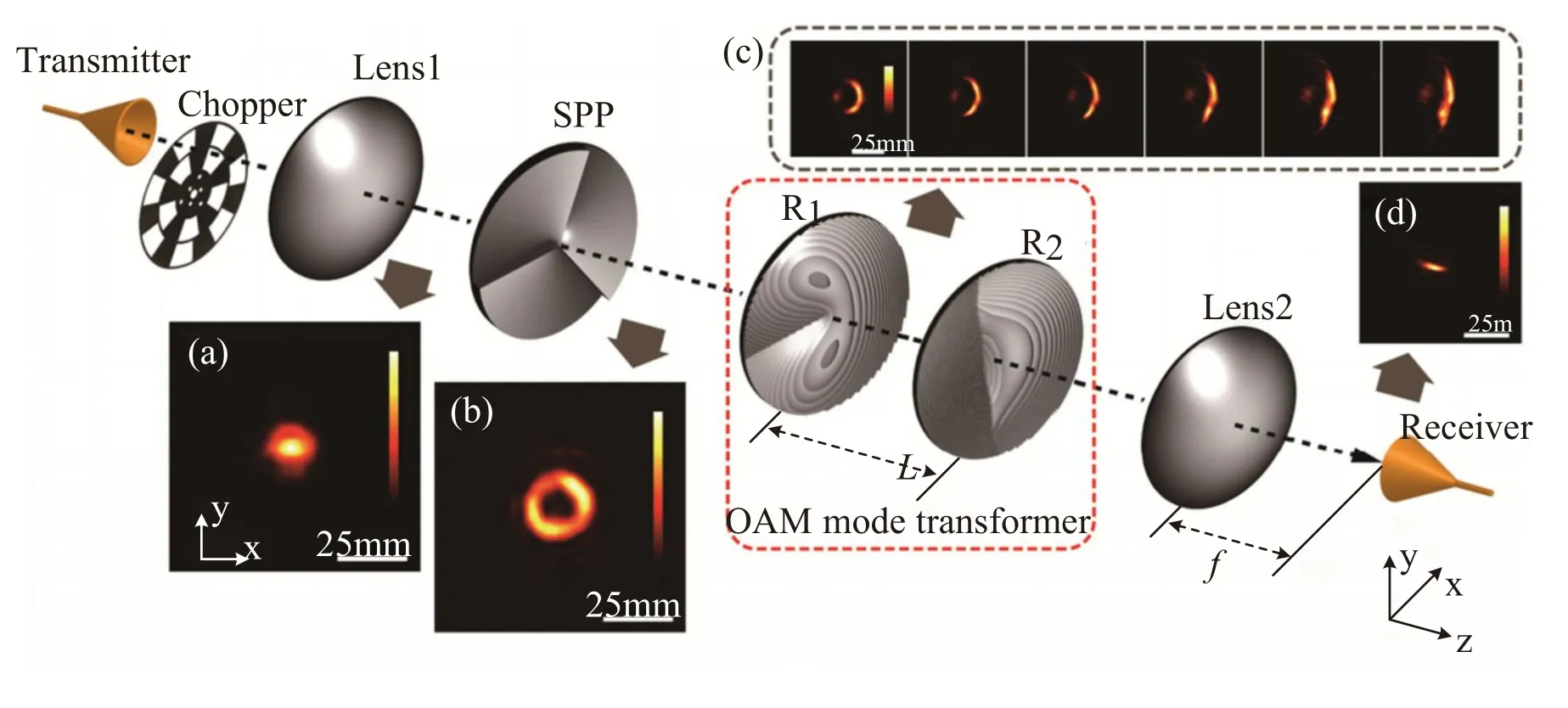
Figure 14.Detection process of coordinate transformation method.The normalized intensity of(a)the collimated THz Gaussian beams,(b)the generated THz-OAM beam,(c)the coordinate transformation process of THz-OAM beam,(d)the focal spot of transformed THz beam[128].
The refraction elements have been proven that they can not only work in the optical and microwave region,but also in the THz region.In 2016,Jinsong Liu et al.proposed the refraction elements that can work at 0.3 THz[128].The refraction elements are combined with the lens to successively focus seven OAM beams with different single modes on different positions of the detection plane.Then,the OAM beam with modes of-1 and+3 generated by the broadcast plate is focused by the lens after passing through the refraction elements.In their experimental results,the beam with the modes of-1 and+3 is focused on two different positions.Therefore,the coordinate transformation method has been proved to be able to separate and detect the OAM beam in the THz region.
Different from the reverse spiral phase plate and plane wave interference method,the coordinate transformation method can simultaneously realize the separation and detection of the OAM beams with multiple different modes.Hence,it is an excellent candidate that can be used for actual communication experiments.However,seen from Eq.(9)and(10),the phase distributions of the refraction elementsR1andR2in this method are related to the distanceDbetween them,which makes it require a large space link and not easy to be integrated.
3.2.3 Electro-optical crystal-based method
Electro-optical crystal method is a widely-used method for detecting THz pulses,and it can also be used to detect THz-OAM beams[132,133].As mentioned in section 3.1,electro-optical crystal method uses the Pockels effect to detect the THz pulses.Figure 15 shows the process of detecting THz pulses by electro-optic crystal method.The linearly polarized probe optical pulse and the THz pulse are illuminated on the electro-optical crystal.Under the effect of the THz electric field,the optical pulse after passing through the crystal could be expressed as[134,135]
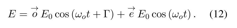
where theΓ=kΔnLis the phase difference between ordinary light and extraordinary light introduced by the birefringence effect of electro-optical crystal,Δnis the refractive index difference between ordinary light and extraordinary light,Lis the thickness of electro-optical crystal,andωois the angular frequency of optical pulse.After the optical pulse passing through the quarter wave plate and being separated by a suitably oriented Wollaston prism,the ordinary light and extraordinary light are sent to two photodetectors,respectively.When theΓapproaches 0,the difference between the output of the two photodetectors could be expressed as
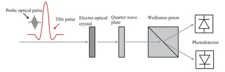
Figure 15.Detection process of electro-optical crystal method.

whereI0=ηE0E*0,ηis the responsibility of photodetector.Since the refractive index differenceΔnis proportional to the electric field of THz pulse,the information carried by the THz pulse could be determined by measuring the output difference between the two photodetectors.
In 2013,Yan Zhang et al.used the electro-optical crystal method to detect the OAM beam at 1 THz[89],and their experiment setup is shown in Figure 16.After passing through the computed hologram on the silicon chip,the THz pulse would be transformed into a THz-OAM beam and illuminated on a ZnTe crystal.Then,a probe beam would be reflected on the ZnTe crystal by a beam splitter,and the information of THz-OAM beam would be modulated on the probe beam through the ZnTe crystal.Finally,the modulated probe beam would be reflected by ZnTe crystal into the imaging module that consists of two lenses,a quarter wave plate,a Wollaston prism and a chargecoupled-device(CCD)camera.The quarter wave plate and Wollaston prism would split the probe beam into two beams with orthogonal polarization,and the information of the THz-OAM beam could be obtained by the CCD camera’s differential detection of two orthogonally polarized beams.In their experimental results,the THz-OAM beams with modes 1 to 3 are successfully detected.In 2017,Yanqing Lu et al.also used the electro-optical crystal method to successfully detect the THz beam generated by the liquid crystal qplate[102].
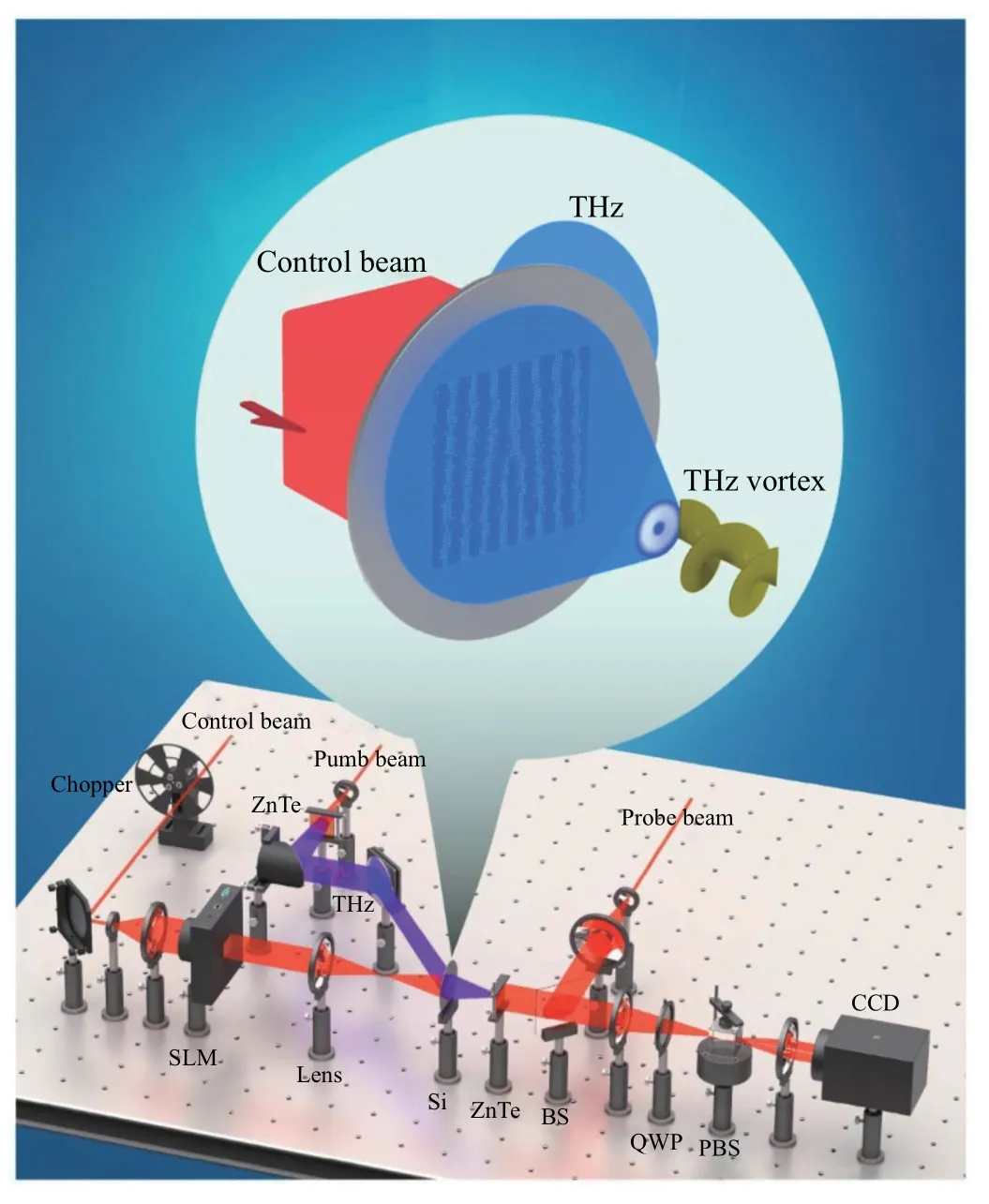
Figure 16.Experiment setup of electro-optical crystal method[89].
The electro-optical crystal method is a mature and widely-used method for detecting THz pulses.It can simultaneously detect the phase and amplitude distribution of THz-OAM beams at high speed.However,due to the low responsibility of electro-optical crystal to THz electric field,this method is usually used to detect THz pulses with large instantons power rather than continuous THz waves.Therefore,electrooptical crystal method is not suitable for THz commu-nication.
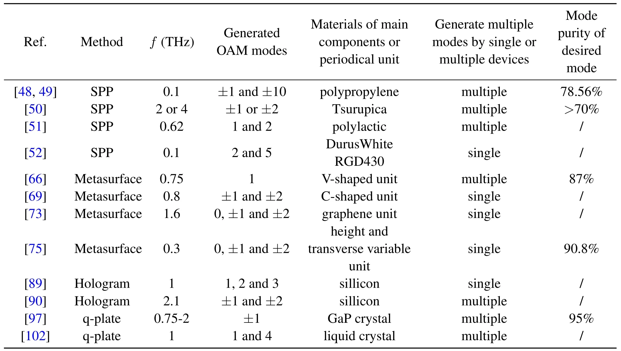
Table 1.Comparison of typical methods for generating THz-OAM beams.
IV.COMMUNICATION BASED ON THZOAM BEAMS
The OAM of electromagnetic wave is a new degree of freedom,which can increase communication capacity because of its infinite mutually orthogonal modes[119].As a new communication dimension,OAM technology can not only improve communication capacity,but its mode can be also used as a symbol of information for communication.Therefore,the applications of OAM technology in communications can be divided into two categories:OAM shift keying and OAM mode multiplexing.
Traditional communication coding realizes data transmission through high-speed modulation of amplitude,frequency,phase and polarization of electromagnetic wave.In the OAM shift keying communication systems,the mode of OAM is used as a new parameter for data transmission.When theNmodes of OAM are used for communication,the carrier beam is loaded withlog2Nbit information.Compared with traditional binary coding,the OAM shift keying can effectively improve the security of communication systems.In 2004,Gibson et al.used SLM to generate optical OAM beams and used eight modes of the OAM beams to encode information[136].This is the first free space optical communication based on OAM shift keying.In addition,they also verified that the OAM encoding has the advantages of anti-eavesdropping.In 2014,Jinsong Liu et al.completed OAM shift keying communication experiments in the THz region[137].They mounted four SPPs with different modes on a 2D rotation stage and generated OAM beams with different modes by controlling the angle of the rotation stage.In the case of switching 1000 states per second,the data transmission rate of this system can reach 2000 bit/s.Obviously,limited by the speed of the rotation stages motor,OAM shift keying cannot be used in high-speed communications temporarily.
The OAM mode multiplexing uses the orthogonal characteristic of different OAM modes to realize the simultaneous transmission of multiple channels of information.Thus,the communication system based on OAM mode multiplexing has been a research hotspot in the communication field.In 2012,Jian Wang et al.proposed an optical communication system based on OAM mode multiplexing[24].They combined polarization multiplexing with OAM mode multiplexing toachieve the transmission of 32 channels information simultaneously,and the data transmission rate reached 2.56 Tbit/s.In the field of millimeter wave communication,OAM mode multiplexing has also played an important role in increasing the communication rate.In 2014,Yan Yan et al.proposed a similar communication system in the microwave region,which achieved 32 Gbit/s of information transmission rate at 28 GHz[131].Unfortunately,limited by the current development status of THz technology,THz communication systems based on OAM mode multiplexing have not yet been proposed.Compared with microwave,THz can provide wider bandwidth,thus we can reasonably predict that the data transmission rate of the THz-OAM mode multiplexing would be greater.
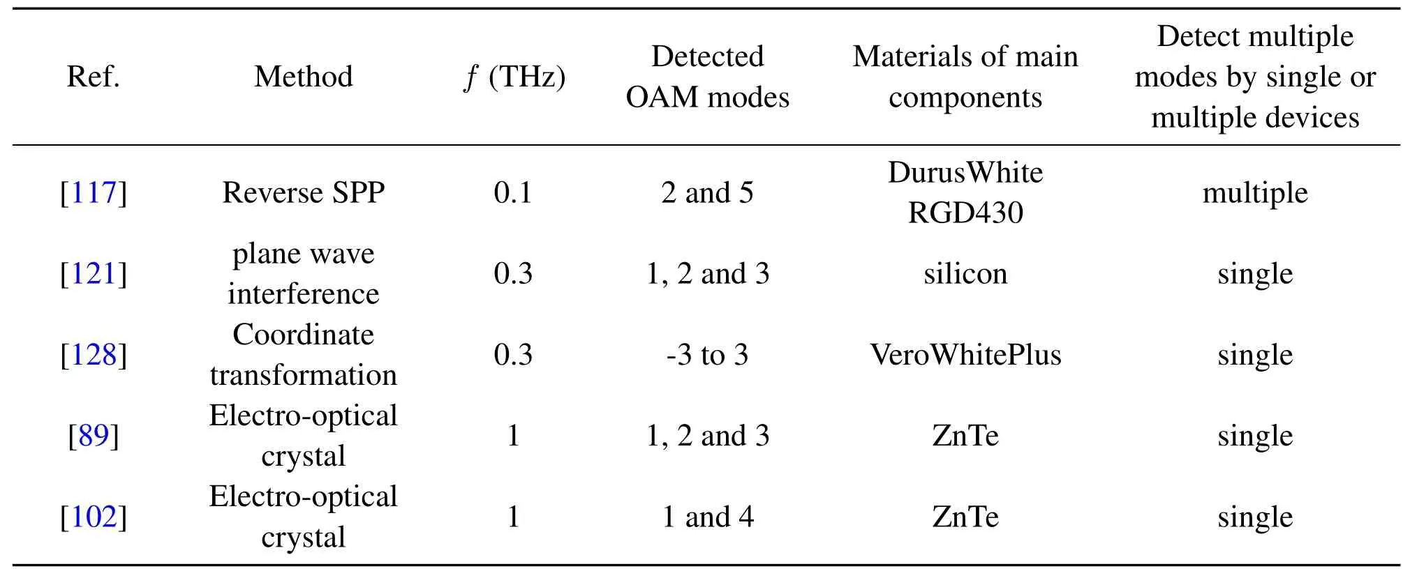
Table 2.Comparison of typical methods for detecting THz-OAM beams.
V.DISCUSSION AND OUTLOOK
Table 1 shows the comparison of typical methods for generating THz-OAM beams.From the practical use,a device that can generate OAM beams with multiple modes can greatly reduce the complexity of overall system.In addition,as an important parameter for evaluating the qualities of the generated OAM beams,the mode purity should also be considered.Due to the higher phase accuracy,the metasurfacebased method and q-plate based method perform better in the mode purity.Hence,the metasurface-based method has greater development potential because of its greater scalability and high performance.
Table 2 shows the comparison of typical methods for detecting THz-OAM beams.From Table 2,the detection methods of THz-OAM beam can be divided into two categories:one can efficiently discriminate the modes of THz-OAM beams,and the other can demodulate the information carried by THz-OAM beams.In terms of achieving the high-speed communication,the latter is more advantageous.As a representative of the latter,the coordinate transformation method is the most promising and practical method.
As a combination of infinite orthogonal modes and wide bandwidth,THz-OAM technology has greatly development potential in the field of wireless communication.Both OAM shift keying and OAM mode multiplexing can provide new development directions of THz communication.However,there are still a series of issues that need to be considered before the technology being applied in practice.For the THz-OAM beams,the mode purity and the working bandwidth would help increase the data transmission rate of THz-OAM communication system,as the former guarantees the orthogonality while the latter ensures the effective spectrum usage.For the communication system,the expensive THz devices and the bulky OAM generation and detection components greatly limit the development of THz-OAM technology.Developing novel THz components in generating,detecting and(de)multiplexing THz-OAM beams has become the key engine to drive this direction forward.Moreover,the integrated design instead of the discrete components is essential to reduce the cost and size in the future.Lastly,considering the characteristics of THz,the THz-OAM communication theory should be studied,for example the transmission performance of the THz-OAM in the practical situations(e.g.the reflection,refraction and multi-path),or even the harsher conditions(e.g.rain,fog,atmospheric turbulence).
ACKNOWLEDGEMENT
This work is supported by the National Key Research and Development Program of China(2020YFB18057002018YFB1801500&2018YFB2201700),the Natural National Science Foundation of China under Grant 61771424,the Natural Science Foundation of Zhejiang Province under Grant LZ18F010001 and Zhejiang Lab(no.2020LC0AD01).
- China Communications的其它文章
- AI Assisted PHY in Future Wireless Systems:Recent Developments and Challenges
- Secrecy-Enhancing Design for Two-Way Energy Harvesting Cooperative Networks with Full-Duplex Relay Jamming
- Adaptive Maxwell’s Equations Derived Optimization and Its Application in Antenna Array Synthesis
- A 16-QAM 45-Gbps 7-m Wireless Link Using InP HEMT LNA and GaAs SBD Mixers at 220-GHz-Band
- A Wideband E-Plane Crossover Coupler for Terahertz Applications
- Terahertz Direct Modulation Techniques for High-speed Communication Systems