Approach for ISAR imaging of near-field targets based on coordinate conversion and image interpolation
ZHOU Xingyu ,WANG Yong,* ,and LU Xiaofei
1.School of Electronics and Information Engineering,Harbin Institute of Technology,Harbin 150001,China;2.Jiuquan Satellite Launch Center,Jiuquan 732750,China
Abstract: Inverse synthetic aperture radar (ISAR) imaging of near-field targets is potentially useful in some specific applications,which makes it very important to efficiently produce highquality image of the near-field target.In this paper,the simplified target model with uniform linear motion is applied to the near-field target imaging,which overcomes the complexity of the traditional near-field imaging algorithm.According to this signal model,the method based on coordinate conversion and image interpolation combined with the range-Doppler (R-D) algorithm is proposed to correct the near-field distortion problem.Compared with the back-projection (BP) algorithm,the proposed method produces better focused ISAR images of the near-field target,and decreases the computation complexity significantly.Experimental results of the simulated data have demonstrated the effectiveness and robustness of the proposed method.
Keywords:inverse synthetic aperture radar (ISAR),near-field imaging,image interpolation,back-projection (BP) algorithm.
1.Introduction
Inverse synthetic aperture radar (ISAR) may generate high-resolution image of non-cooperative targets by utilizing the relative motion between the radar and the target,and it has been widely used for military and civilian purposes.The high range resolution is achieved by the pulse compression of the wideband signal,whereas the high azimuth resolution is realized by the coherent processing.In traditional ISAR imaging for small scenes,the far-field condition and short integration time are usually assumed,which is generally satisfied in typical ISAR scenarios when the required resolutions are not very high.Thus,the consequent effect is that the radar echo would contain target information relative to thex-andy-coordinates independently within the limits of the far-field condition.After the translational motion compensation including range alignment and phase adjustment,the target can be viewed as a turntable model,and the classical range-Doppler(R-D) algorithm can be applied to obtain the focused ISAR image [1].
However,in some specific applications,such as indoor concealed object detection [2−4],far-field radar cross section (RCS) determination by near-field ISAR imaging [5,6],and ISAR imaging for near-field targets in the missile-target encounter [7−9],where the target is not located far enough from the radar,the incident wavefront cannot be treated as a plane wave.Due to the short range between the radar and the target,and the comparably large size of the target,the target will be in the near-field region of the radar.The R-D imaging algorithm for nearfield targets leads to errors in parts of the scene far away from the central reference point.
In recent years,several ISAR imaging algorithms for the near-field target have been proposed.The near-field spherical wave ISAR imaging algorithm using fast cyclical convolution for the image computation was proposed in [10],and this imaging technique is extended to threedimension (3-D) imaging [11]and employed for far-field RCS extraction [5].The imaging algorithm for terahertz ISAR using the Green function decomposition was proposed in [12]to implement near-field imaging,which required the echo data to be recorded with polar grid.The back-projection (BP) algorithm was first proposed for synthetic aperture radar (SAR) image reconstruction [13]and ISAR imaging processing [14].Since the BP algorithm does not require the approximation of the instantaneous range,it can be used in the near-field region to reconstruct the image of the target [2,15].The BP algorithm is based on tracing back the matched-filtered signal signature of the imaging scene in the fast-time domain at each slow-time,and coherently adding the results at the available slow-time values.However,the BP algorithm has much higher computational loads than Fourier-based algorithms.
The above near-field ISAR imaging algorithms are all based on the turntable model,which makes the imaging formula very complicated.In this paper,according to the general characteristics of near-field targets imaging,the uniform linear motion model of near-field targets is established.In this model,the position of the scatterer is recorded in the radar echo in the form of polar coordinates.Thus,the imaging method for near-field targets based on coordinate conversion and image interpolation [16,17]is proposed.The simulation results validate that the proposed algorithm can produce a better focused image efficiently than the BP algorithm,and correct the near-field target distortion even at a relatively low signal-to-noise ratio (SNR).
The structure of this paper is organized as follows.In Section 2,the radar signal of the turntable model is reviewed,and the signal model of the near-field target with uniform linear motion is analyzed.The proposed method for the near-field target ISAR imaging based on coordinate conversion and image interpolation is described in Section 3.Simulation and experimental results are presented in Section 4 to demonstrate the effectiveness of the proposed method.Finally,Section 5 makes a conclusion of this paper.
2.Signal model of the near-field target
2.1 Turntable model
ISAR exploits the relative motion between the radar and the target to obtain azimuth image resolution.The relative motion can be divided into three parts:the rotation of the target around the radar,the translation of the target along the line of sight (LOS),and the rotation of the target around the target center,which is the desired component of ISAR imaging processing.The target can be treated as the turntable model after motion compensation,and the R-D imaging algorithm can be used to obtain a focused ISAR image of the target.
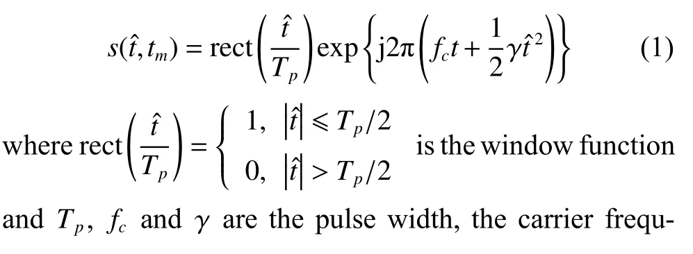
In practice,in order to increase transmit power of the radar and obtain high range resolution,the linear frequency modulation (LFM) signal is adopted and the range compression technique is employed.The expression of the transmitted signal (chirp signal) is

After dechirping,and removing the residual video phase (RVP) and the envelope migration phase,the radar echo can be expressed as

where σ,c and λ are the backscattering coefficient,the speed of light,and the wavelength,respectively.∆R(tm) is the instantaneous range from the scatterer to the reference point.
The imaging plane of the target is denoted asXOY,and the turntable model rotates uniformly around the target centerOat an angular velocity ω.The coordinate of the radar is (0,−r0).The instantaneous rangeR(tm) from the scattererPthat positions at (xP,yP)=(rPcosθP,rPsinθP)to the radar satisfies

For the ISAR imaging,the range from the radar to the target center is far larger than the expansion size of the target,i.e.,r0≫rP.Taking the target centerOas the reference point,the instantaneous range ∆R(tm) can be approximated to

whereRrefis the range from the radar to the reference point.The approximation in (4) is made under the plane wave model assumption and the small angle assumption ωtm≈0.
Combining (2) and (4),the ISAR image of the target can be reconstructed by directly applying two-dimensional(2-D) fast Fourier transform (FFT) to the radar echo.

where sinc(x)=andTallis the imaging time.
Based on the above far-field assumption,the instantaneous range ∆R(tm) is simplified.The 2-D coordinates of the target in the spatial domain are independently mapped to the R-D plane,so the target can be well presented in the reconstructed image.However,for the near-field target,the expansion size of the target has a large effect on the radar echo and the above assumption is not always feasible.
In particular,when the range difference of the azimuth scatterers on the target exceeds a range resolution bin,the target will be distorted on the R-D image [7,8].The geometry of the near-field imaging is shown in Fig.1.The range from the radar to the target center isR,and the expansion size of the target isD.If the range resolution is δR,the condition for image distortion is

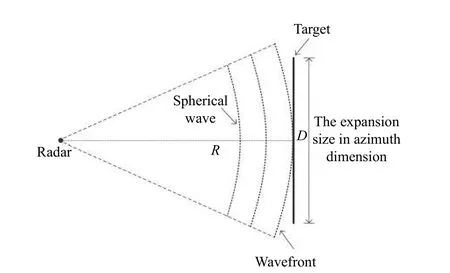
Fig.1 Near-field imaging geometry
The following simulation experiment is used to illustrate the image distortion problem.In the simulation of the turntable model,the point-scatterer model of the target is shown in Fig.2,and the expansion size of the targetDis 10 m,the range resolution δRis 0.15 m.In order to ensure that the image is not distorted,it is required that the range from the radar to the target centerR>80 m.The imaging results of the turntable model with different ranges directly using the R-D algorithm are shown in Fig.3.It can be seen from the experimental results that when the target is not far from the radar,the target will be distorted and the R-D image cannot reflect the shape of the target.
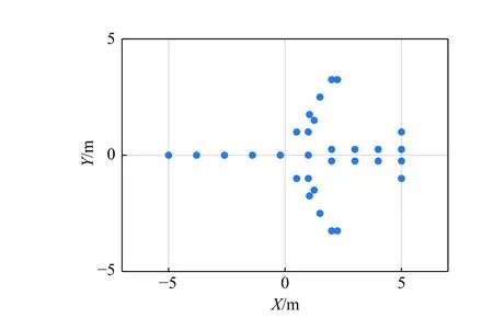
Fig.2 Point-scatterer model of the target
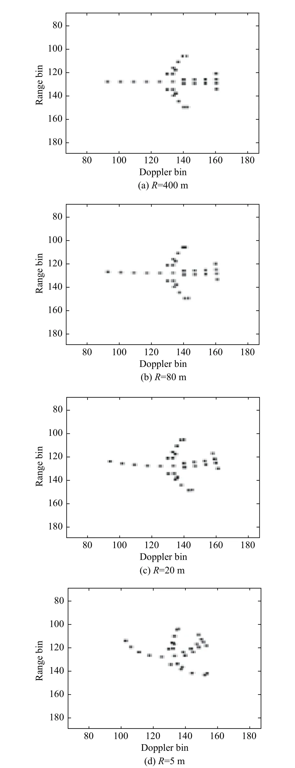
Fig.3 Imaging results of the far-field and near-field turntable model with the R-D algorithm
For the near-field target,the turntable model makes it more complicated to analyze the ISAR imaging problem.The following is the imaging model of the near-field target with uniform linear motion.
2.2 Imaging model of the near-field target with uniform linear motion
The point-scatterer model is usually used in radar imaging to model the radar echo of the target.Without loss of generality,the imaging model is considered on the 2-D plane that is unchanged during the imaging time.The imaging geometry of the radar and the target is shown in Fig.4.The radar is stationary and located at the originO′of the radar coordinate systemX′O′Y′.The target moves with a velocityvalong the direction of theX′-axis.XOYis the local coordinate system for the target,and the coordinates of the originOin the radar coordinate system are (x0,y0).
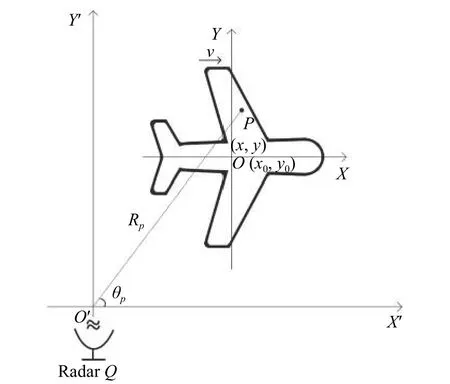
Fig.4 Imaging geometry of the near-field target
Assume that there is a scattererPon the target with the position (xP,yP).The initial range from the scattererPto the radar isRP(t0),and the initial angle of theO′Pin theX′O′Y′is θP(t0).The instantaneous rangeRP(tm) from the scattererPto the radar satisfies

Under near-field condition,the expansion size of the target is equivalent to the range from the radar to the target center,and a more suitable approximation method should be proposed.Since the range from the radar to the target is relatively short,the slight relative movement can accumulate the larger rotation angle to achieve azimuth resolution.Therefore,the relative movement of the target during the imaging time satisfiesApplying the Taylor series theorem and ignoring higher-order terms,the instantaneous rangeRP(tm) can be approximated to
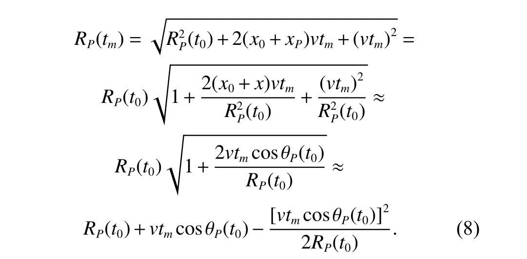
In this assumption,the instantaneous rangeRP(tm) can be simplified as

Assuming that the relative movement of the target during the imaging time does not exceed one range bin,the range migration termvtmcosθP(t0) in (9) can be ignored in the range domain,otherwise range alignment is required.Combining (2) and (9),and taking the radarO′as the reference point,the radar echo can be expressed as

The radar echo after directly applying 2-D FFT can be expressed as
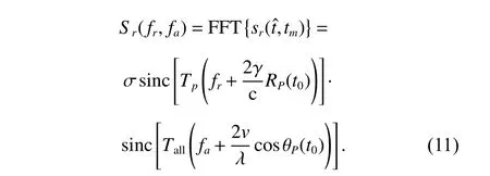
From the above derivation,it can be seen that using the R-D algorithm to image the near-field target,the range domain of the image reflects the initial rangeRP(t0) of the target,and the Doppler domain of the image reflects the cosine value of the initial angle cosθP(t0) of the target.The method based on the coordinate conversion and image interpolation can be applied to obtain the target image in the Cartesian coordinate system.
2.3 Imaging resolution of near-field targets
For the reconstructed image of the near-field target directly using the R-D algorithm,the range resolution depends on the bandwidth of the transmitted signal and can be calculated through

The angular resolution is related to the relative movement distancevTallin the spatial domain and can be achieved by the following equation:

Taking the millimeter-wave radar with the center frequency of 77 GHz and the bandwidth of 1 GHz as an example,its range resolution is 0.15 m.Assuming the angular resolution is δcosθP(t0)=0.02,which only requires the relative movement distancevTall=0.1 m during the imaging time.The spatial resolution of the above parameters is shown in Fig.5.In Fig.5,the radar is located at (0,0)in the radar coordinate systemX′O′Y′,the interval of the range distance is 0.15 m,and the interval of the cosine of the azimuth angle is 0.02.Due to the characteristics of the cosine function,the angular resolution of the radar is not uniform in the spatial domain,and when the azimuth angle is about 90◦,fine resolution results can be obtained.Therefore,better resolution can be achieved in the circle,which corresponds to the denser area in Fig.5,and the azimuth resolution in the circle is approximately better than 0.15 m.It can be concluded that the azimuth resolution can be achieved by relatively small motion under near-field condition,which further illustrates the rationality of the above-mentioned range approximation.
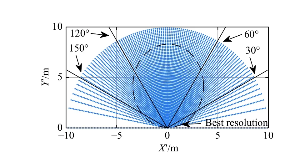
Fig.5 Spatial resolution of the near-field imaging
3.Near-field target imaging algorithm based on coordinate conversion and image interpolation
In Section 2,the imaging formula of the near-field target with uniform linear motion directly using the R-D algorithm is analyzed in detail.The R-D image of the target records the position information of the target scatterer in the form of polar coordinates:the polar radius of the target is recorded in the range domain,and the cosine of the polar angle is recorded in the Doppler domain.The image of the target in the Cartesian coordinate system can be obtained through coordinate conversion and image interpolation.The process of coordinate conversion and image interpolation for the near-field target R-D image can be illustrated by Fig.6.
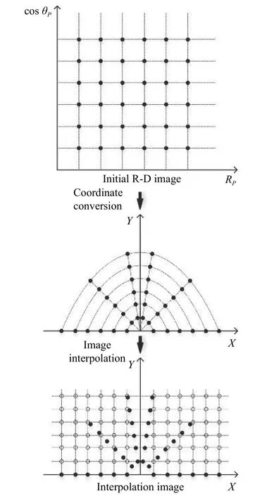
Fig.6 Coordinate conversion and image interpolation of the R-D image
Specifically,the R-D image of the near-field target can be obtained by applying 2-D FFT to the radar echo.The initial R-D image with the rectangular data distribution records the position of the target in polar format.Convert data from polar coordinates to Cartesian coordinates by

The target image in the Cartesian coordinates system can be obtained.However,the data distribution of the intermediate image changes to the polar sector.The sampling interval in the spatial domain is not equivalent.The image interpolation can transform non-uniform sampling in the spatial domain to uniform sampling.After interpolation,the data distribution changes from the polar sector area to the rectangular area,and the data interval becomes even.
3.1 Image interpolation
Image interpolation is the process of estimating the unknown pixels by employing the known neighbors,which is used extensively in digital image processing to magnify or reduce images and to correct spatial distortions.Traditional linear image interpolation algorithms involving nearest-neighbor,bi-linear and bi-cubic are the most widely used methods in practice.Compared to the non-linear methods,the linear case cannot locally adapt the interpolated values to the given data,but it has a less computational complexity.The nearest-neighbor algorithm uses the nearest sample as the interpolated value.The bi-linear algorithm explores four nearest neighboring points around the interpolation point in the source image,and assumes that the value function is linear in this neighborhood.However,the kernel functions used in the above methods can only exactly reconstruct any zero-degree or first-degree polynomial.Thus,these interpolation algorithms are prone to producing zigzagging artifacts along edges and blurring details in textures.In that regard,the bi-cubic kernel provides a very good trade-off in terms of performance and computational time for general applications.By using cubic convolution instead of bilinear interpolation or nearest-neighbor resampling,the complexity of functions that can be exactly reconstructed is increased to the second-degree.
Bi-cubic interpolation,also known as cubic convolution interpolation,estimates the interpolated value by weighted average of the 16 pixels closest to the interpolation point in the source image.Assume thatgrepresents the source image,andfrepresents the destination image.For the point (x,y) inf,the bi-cubic interpolation can be presented as

wherel=⌊x⌋,that is,lis the value ofxrounded down to the nearest integer,andk=⌊y⌋.The cubic convolution interpolation kernelu(s) is defined as

where |s| represents the distance between the interpolation pixel and the reference pixel.The constrainta=−0.5 is the only choice that will achieve the best precision[16].u(s) can be written as

The interpolation process of the point (x,y) in the imagefcan be depicted in Fig.7.
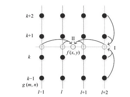
Fig.7 Bi-cubic image interpolation
Actually,2-D bi-cubic interpolation is accomplished by performing one-dimensional (1-D) interpolation in each dimension,which can be indicated by I and II in Fig.7.Additionally,the algorithm requires that the data samples are assumed to be equally spaced.However,in the 2-D case,the horizontal and vertical sampling increments do not have to be the same.Therefore,the interpolation process needs to be adjusted appropriately,which will be described in detail in the next section.Finally,the original intention of interpolation is image resolution improvement and image scaling.In this application,it is used to compensate for nonhomogeneous sampled data to complete coordinate conversion.Therefore,the interpolation interval should not be too small or too large.The interpolation interval that is too small will increase the amount of calculation,and the interpolation interval that is too large will cause the target image to be rough.The literature points out that the interval of interpolation should be one third of the radar resolution.
3.2 The proposed imaging algorithm for near-field targets
The flowchart of the proposed imaging method for nearfield targets is shown in Fig.8.
The steps in the flowchart will be specifically described below.
Step 1Perform dechirping processing,range compression,and the R-D imaging algorithm on the radar echo of the target with the uniform linear motion to obtain the R-D image of the targetg(RP,cosθP).If the relative movement of the target during the imaging time does not exceed one range bin,the range alignment can be ignored,otherwise range alignment is required.
Step 2Define imaging grid (x,y),including imaging range and grid spacing.
Step 3Convert grid coordinates in Cartesian form(x,y) to coordinates in polar form (R,cosθ).The grid spacing is no longer uniform in theR−cosθ plane.
Step 4In theR−cosθ plane,interpolate the R-D imageg(RP,cosθP) to grid coordinates (R,cosθ) to obtain the destination imagef(R,cosθ).The R-D imageg(RP,cosθP) has uniform intervals in theR−cosθ coordinate system,which meets the requirement of bi-cubic interpolation.
Step 5Convert grid coordinates in polar form(R,cosθ) to coordinates in Cartesian form (x,y).The target imagef(x,y) with uniform intervals in thex−yplane is obtained.
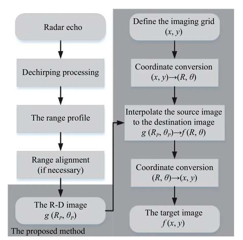
Fig.8 Flowchart of ISAR imaging algorithm for near-field targets
4.Experiment and performance analysis
In this section,the simulated data is used to demonstrate the effectiveness of the proposed method,and the BP algorithm in literature is used for comparison.
The simulation is performed in the point-scatterer model with uniform linear motion.The point-scatterer model of the target is shown in Fig.2.In the model,there are 30 scatterers with the same backscattering coefficient.The target moves in a straight line at the velocity of (−5,0) m/s in the imaging plane,that is,the target moves at a constant velocity of 5 m/s in the opposite direction ofX′-axis in the radar coordinate system.
The radar transmits LFM signals with the center frequency being 77 GHz,the bandwidth being 1 GHz and the time width of the pulse being 25.6 μs,and the pulse repetition frequency (PRF) is 10 kHz.A total of 256 range samples and 256 Doppler samples are selected for radar imaging processing.The target moves 0.128 m during the imaging time.In the simulation,the relative movement of the target does not exceed one range bin δR=0.15 m,and the range alignment can be ignored.
4.1 Experiments on the target with different spatial locations
In this section,the proposed method is applied to experiments in different near-field scenes.The position of the target center in the radar coordinate system can be expressed as (R0,θ0) in polar coordinates form.In different scenarios,the spatial coordinates of the target center are shown in Table 1.

Table 1 Spatial coordinates in different scenarios
For Scenario 1,the imaging geometry of the radar and the target is shown in Fig.9(a).The point-scatterer model and radar parameters are described as above.The radar echo is generated by the above signal model.Fig.9(b)shows the ISAR image of the simulated data by directly using the R-D algorithm.As shown in the figure,the R-D image of the target is distorted,and the shape of the target cannot be presented correctly.
The results of near-field imaging using the proposed method and the BP algorithm are shown in Fig.9(c) and Fig.9(d),respectively.Specifically,the imaging range is set to 30 m,and the grid spacing is set to 0.1 m in both algorithms.The accurate speed of the target needs to be obtained in advance to complete coordinate conversion in the proposed method,and coherent accumulation in the BP algorithm,respectively.Otherwise,the BP algorithm will become unproductive,and the proposed method will have the cross-range scaling problem.
The entropy is calculated to measure the focus of the image based on the conclusion that better focused image results in smaller entropy.The entropies of the ISAR images based on the proposed method and the BP algorithm are shown in Table 2.The computational cost analysis of the two methods for near-field target imaging are shown in Table 3.
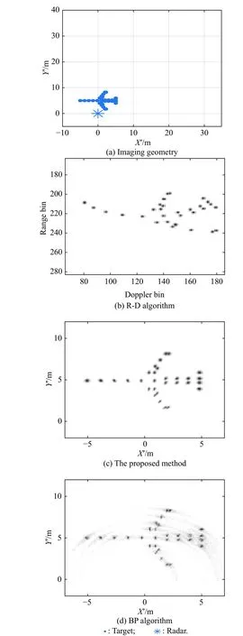
Fig.9 Imaging geometry in Scenario 1 and imaging results based on the R-D algorithm,the proposed method,and the BP algorithm
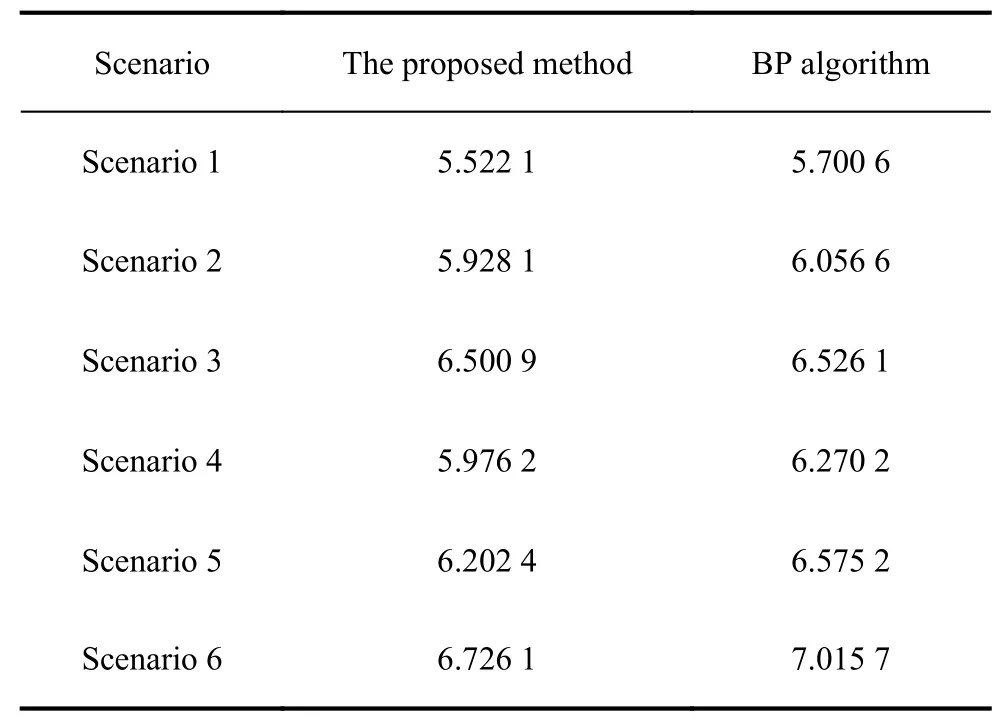
Table 2 Image entropies of different algorithms
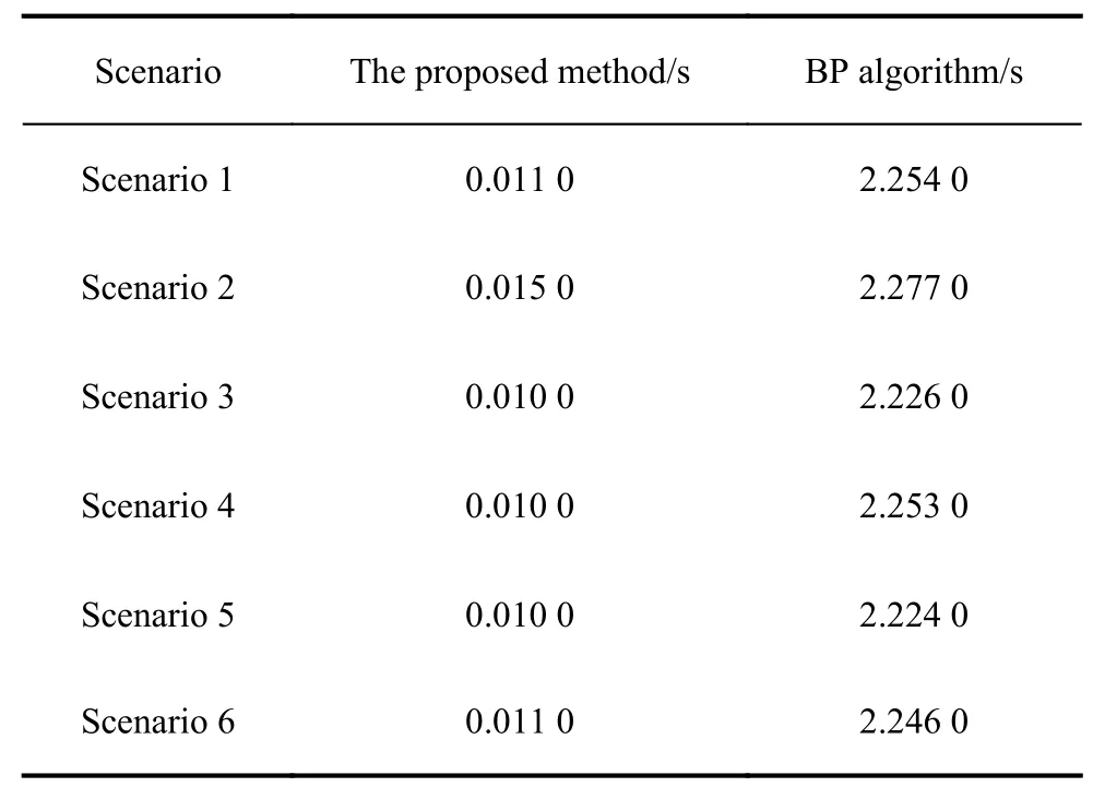
Table 3 Time consumed of different algorithms
For the BP algorithm,it performs coherent accumulation on 2-D grid points for each echo,and the time complexity isO(N3).The major steps of the proposed method mainly include polynomial calculation on 2-D grid.The time complexity of the proposed method isO(N2).
According to the imaging results,the near-field imaging algorithms can achieve the correction of the target distortion.Compared with the BP algorithm,it is obvious that the image quality of the proposed method is improved.In addition,the consuming time of the proposed method is much lower than the BP algorithm,which makes it possible for real-time applications.Overall,the experimental results show that the proposed method can get better focused image efficiently.
The same experimental analysis process is applied to Scenarios 2−6.The experimental results of Scenarios 2−6 are shown in Figs.10−14,the entropies of the images and the computational cost analysis are shown in Table 2 and Table 3,respectively.The same conclusion can be summarized through the experimental results.
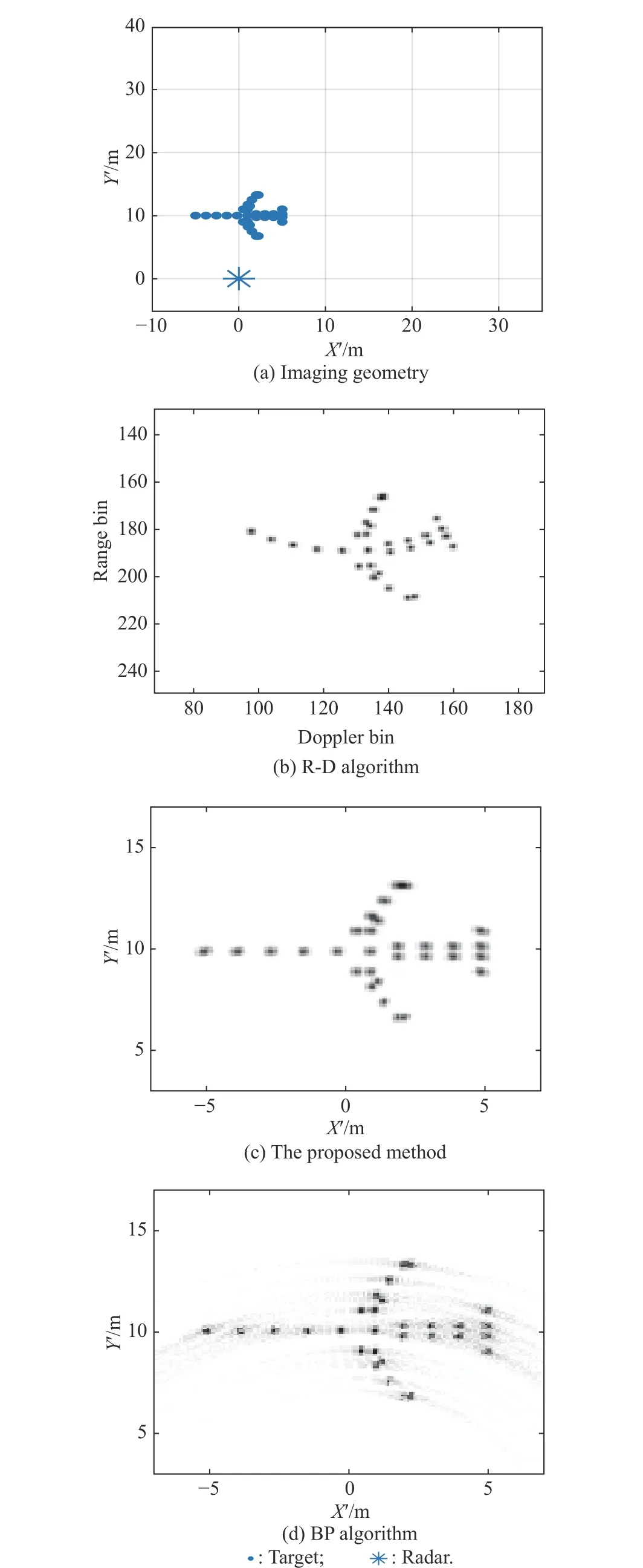
Fig.10 Imaging geometry in Scenario 2 and imaging results based on the R-D algorithm,the proposed method,and the BP algorithm
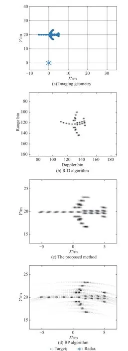
Fig.11 Imaging geometry in Scenario 3 and imaging results based on R-D algorithm,the proposed method,and the BP algorithm
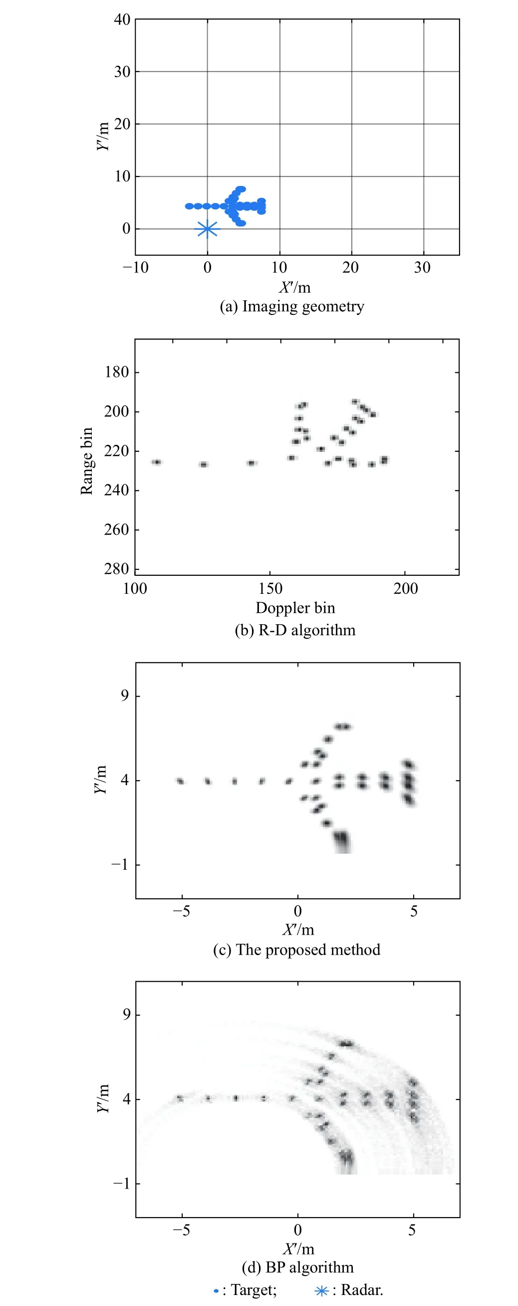
Fig.12 Imaging geometry in Scenario 4 and imaging results based on the R-D algorithm,the proposed method,and the BP algorithm
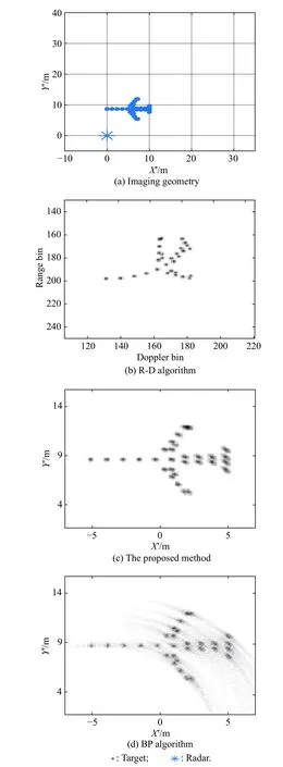
Fig.13 Imaging geometry in Scenario 5 and imaging results based on the R-D algorithm,the proposed method,and the BP algorithm
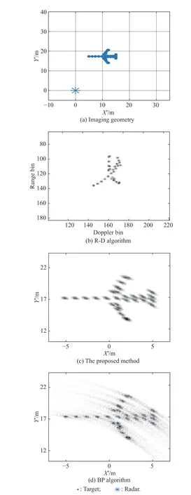
Fig.14 Imaging geometry in Scenario 6 and imaging results based on the R-D algorithm,the proposed method,and the BP algorithm
4.2 Experiments with different SNRs
In this section,the experiments with different SNRs are investigated to validate the robustness of the proposed method.The additive complex Gaussian noise is added to the radar echo in Scenario 2,and the yielding SNR varies from 0 dB to 20 dB with a step size of 5 dB.The proposed method and the BP algorithm are tested with 300 Monte Carlo trials for each value of SNR.The average image entropy under each SNR is shown in Fig.15.It can be seen that the proposed method outperforms the BP algorithm when the SNR varies from 0 dB to 20 dB.
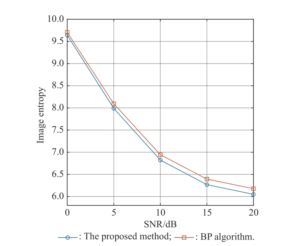
Fig.15 Average image entropy versus SNR
5.Conclusions
In this paper,we consider radar imaging of the near-field target with uniform linear motion,and the method is proposed for near-field ISAR imaging.For the near-field target,the far-field assumption in the traditional ISAR imaging processing chain does not hold.Due to the complication of the near-field turntable model for the analysis problem,the near-field model with uniform linear motion is analyzed.Through reasonable approximation,it is found that the target R-D image records the position information of the target scatterers in the form of polar coordinates.We then propose and apply a new method that,based on the coordinate conversion and image interpolation,obtains the ISAR image of near-field targets in the Cartesian coordinate system.Compared with the BP algorithm,the proposed method produces a better quality of the near-field target ISAR image.Simulation and experimental results have evidently demonstrated the efficiency and robustness of the proposed method.
 Journal of Systems Engineering and Electronics2021年2期
- Journal of Systems Engineering and Electronics的其它文章
- Data-driven evolutionary sampling optimization for expensive problems
- A dual population multi-operator genetic algorithm for flight deck operations scheduling problem
- Observation scheduling problem for AEOS with a comprehensive task clustering
- An improved estimation of distribution algorithm for multi-compartment electric vehicle routing problem
- VCR-LFM-BPSK signal design for countering advanced interception technologies
- RFC:a feature selection algorithm for software defect prediction
