VCR-LFM-BPSK signal design for countering advanced interception technologies
WANG Shanshan,LIU Zheng,XIE Rong,and WANG Jingjing
National Laboratory of Radar Signal Processing,Xidian University,Xi’an 710071,China
Abstract: The hybrid waveform of linear frequency modulation and binary phase shift keying (LFM-BPSK) can take advantages of the LFM and BPSK signals,and reduce the defects of them.However,with the development of interception technology for the LFM-BPSK signal,the application of the signal is limited.In this paper,to improve the anti-interception performance of the hybrid waveform,a new waveform of LFM-BPSK with the varying chirp rate (denoted as VCR-LFM-BPSK) is designed.In this design,based on the working principle of the interception frame for the LFM-BPSK signal,different chirp rates are introduced in different sub-pulses to prevent the signal from being intercepted by the frame.Then,to further improve the anti-interception performance of the VCR-LFM-BPSK signal,the chirp rates are optimized by minimizing the interception capability of the interceptor.Moreover,based on the VCR-LFM-BPSK signal with the optimized chirp rates,the binary phases are designed via a multiobjective Pareto optimization to improve the capabilities of autocorrelation and spectrum.Simulation results demonstrate that the designed VCR-LFM-BPSK signal outperforms the traditional LFM-BPSK signal in countering the advanced interception technologies.
Keywords:hybrid waveform,waveform design,anti-interception,optimization.
1.Introduction
Electronic intelligence (ELINT) interception is an important part of electronic countermeasures (ECM) which mainly consists of signal detection,signal recognition and signal parameter estimation [1,2].Based on the intercepted parameters,jamming signals are transmitted by countermeasure systems to weaken the performance of radar.To reduce the probability of interception,researchers propose several methods [3−9],of which the pulse compression signal is an effective one [8,9].Linear frequency modulation (LFM) and binary phase shift keying (BPSK)are two typical pulse compression signals.The LFM signal can realize large time-bandwidth product conveniently and has a low Doppler sensitivity,but it has a coupling effect of range and velocity.The BPSK signal has a low autocorrelation peak sidelobe level (PSL),but it is sensitive to Doppler frequency shift.In addition to the defects above,both LFM and BPSK signals are prone to be intercepted due to single modulation.Considering this,the hybrid waveform of LFM and BPSK (LFM-BPSK) is proposed to take advantages of the signals and reduce the defects of them [10,11].
However,ECM and electronic counter-countermeasures (ECCM) are developed mutually.To counter the LFM-BPSK signal,the parameter interception technologies for the LFM-BPSK waveform are proposed [12,13].The main idea is to separate the modulation of the signal,and further to estimate the parameters of LFM and BPSK.The classical parameter interception frame for the LFMBPSK signal includes three steps,i.e.,the square method,chirp rate and frequency estimation,and phase code reconstruction.Based on the interception frame,all parameters of the LFM-BPSK signal can be easily estimated,which adversely affects the signal application in ECM environment.
In this paper,to improve the anti-interception performance of the LFM-BPSK signal,a novel waveform,named as LFM-BPSK with varying chirp rate (VCR-LFM-BPSK),is designed to counter the advanced interception technologies.The contribution of our work is threefold.First,the VCR-LFM-BPSK introduces different chirp rates in different subpulses,which can prevent parameters from being estimated by the interception frame for the LFMBPSK signal.Second,the chirp rates of the VCR-LFMBPSK are optimized to avoid the commonly used interception technology called the dechirping method.Finally,the phase codes of the VCR-LFM-BPSK signal are designed by a multi-objective Pareto optimization,which can improve the autocorrelation and spectrum capabilities of the transmit signal.In numerical examples,the effectiveness of the designed chirp rates and phase codes is verified by comparing with the random sequences.Besides,the performance of the designed VCR-LFM-BPSK signal for countering advanced interception technologies is demonstrated by comparing with traditional radar signals.
The rest of the paper is organized as follows.The VCRLFM-BPSK signal is developed in Section 2.In Section 3,the parameters of the VCR-LFM-BPSK signal are optimized.Numerical examples are given in Section 4 to demonstrate the effectiveness of the work.Finally,the conclusions are presented in Section 5.
2.LFM-BPSK with VCR
In this section,the VCR-LFM-BPSK signal is developed to prevent transmit parameters from being estimated by the interception frame for the hybrid signal.
As we know,the expression of the LFM-BPSK signal is

whereIis the number of subpulses,rect(t/Tc) is a rectangular wave with widthTc,f0is the carrier frequency,ϕi=π×{0,1}denotes the binary phase of the (i+1)th subpulse,andKis the chirp rate of the signal.
Some interception technologies have been proposed to estimate the parameters of the LFM-BPSK signal [12,13].The main idea of the multi-parameter estimation for the LFM-BPSK is to separate the modulation of the signal and further to estimate the parameters of the LFM signal and the BPSK signal.Generally,the parameter interception frame for the LFM-BPSK signal consists of three steps in Fig.1.

Fig.1 Parameter interception frame for the LFM-BPSK signal
Performing the square method on the LFM-BPSK signal results in
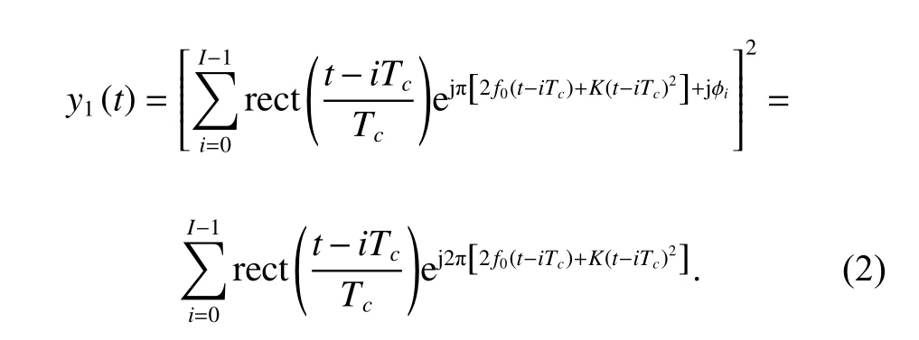
It can be seen in(2) that the phase code symbol ±1 of the LFM-BPSK signal is changed to 1 by the square method.Consequently,the parameters ofy1(t) can be estimated by the interception method in [14].Based on the estimated chirp rateK′and frequencyf0
′,the reconstructed result of the LFM in (1) is

Then,the baseband BPSK signal can be obtained by multiplying the intercepted LFM-BPSK signal and the conjugate of the LFM signal in (3),which is given as follows:

Based on (4),the phase codes can be reconstructed easily.
From the analysis above,since the chirp rates of the LFM-BPSK signal are the same in different sub-pulses,the signal is prone to be intercepted after performing the square method.Accordingly,we introduce different chirp rates in different sub-pulses to form a new waveform named as VCR-LFM-BPSK to improve the anti-interception performance.The expression of the VCR-LFMBPSK signal can be written as

wherekidenotes the chirp rate of the (i+1)th sub-pulse and satisfies
Similarly,performing the square method on the VCRLFM-BPSK,the output signal is
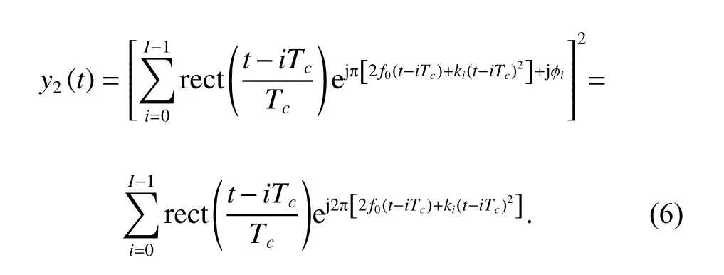
As shown in (6),the output signal for the VCR-LFMBPSK is composed of multiple LFM signals with different chirp rates,which makes it harder to be estimated by using the method in [14].
From the analysis above,the VCR-LFM-BPSK signal outperforms the traditional LFM-BPSK signal in countering the interception frame in Fig.1.However,the value ofkicannot vary without any limits.
On one hand,the maximum value ofkiinfluences the time resolution.Based on (5),the frequency ranges of the subpulses are shown in Fig.2.
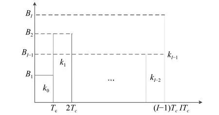
Fig.2 Frequency ranges of the sub-pulses for the VCR-LFMBPSK signal
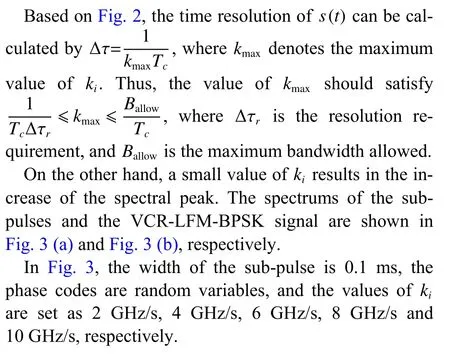
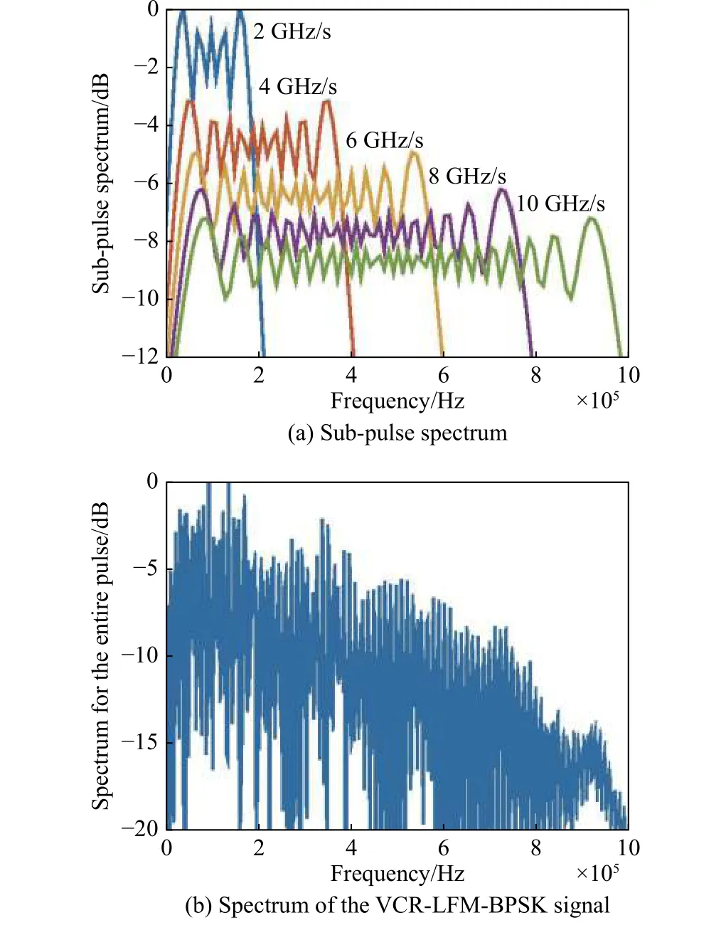
Fig.3 Spectrum of VCR-LFM-BPSK signal with five sub-pulses
Based on the analysis above,the values ofkminandkmaxcan be preset by balancing radar performance.With the presetting range [kmin,kmax],the specific value ofkiwill be designed in the following part.
3.Optimization of the parameters
3.1 Optimization of the chirp rates
The dechirping method can effectively decrease the low probability of interception (LPI) performance of the LFM signal by converting the wideband signal into the narrowband signal,so it has been widely used in interceptors.Furthermore,the dechirping method can act on other signals that possess LFM features,like LFM-BPSK and VCR-LFM-BPSK signals.Considering the dechirping signalg=ejπνt2,the output signal after dechirping in the frequency domain is

The output peak µ obtained by dechirping is

where |·| denotes the absolute value,max {·} denotes the maximum value.
Accordingly,the optimization of chirp rates for countering the dechirping method can be formulated by
When the girl was alone the little man appeared for the third time, and said: What ll you give me if I spin the straw for you once again? I ve nothing more to give, answered the girl

wherekminandkmaxhave been preset based on the analysis in Section 2.In practice,the values thatkican take are limited and discrete,so the problem formulated in (9) can be solved by the genetic algorithm (GA).
3.2 Optimization of the phase codes
In this subsection,based on the VCR-LFM-BPSK with chirp rates obtained by (9),the phase codes are designed by a Pareto-optimization.
Following the analysis in Section 2,to improve the spectrum ability of the VCR-LFM-BPSK,the phase codes can be optimized as follows:

where Ω2represents the finite alphabet codes.Precisely,Ω2={c|ci∈ψ2,i=1,···,I}wherecdenotes the possible phase code vector and ψ2={0,π}.
Besides,for pulse compression operated at the radar receiver,low autocorrelation PSL is needed to avoid the omission of weak targets.The autocorrelation function of the signal is defined as
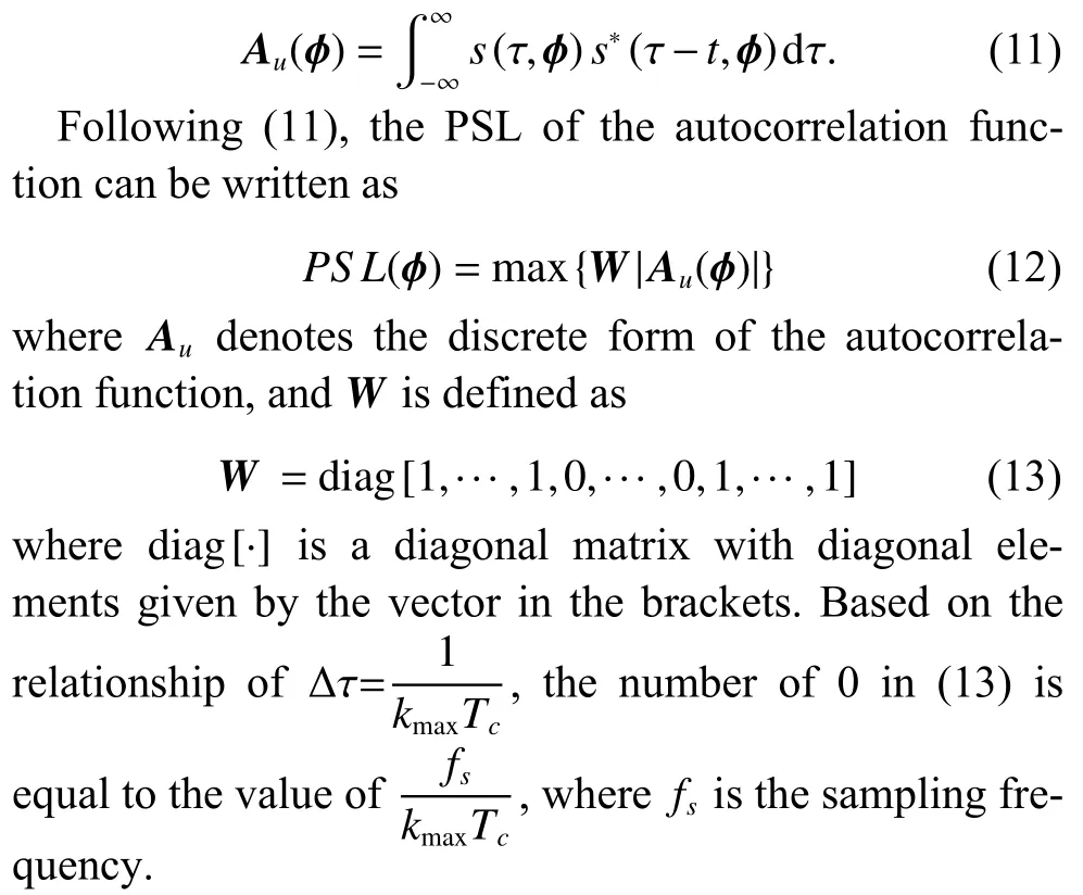
Then,by simultaneously considering the autocorrelation and spectrum as performance guideline,the phase code optimization problem can be formulated as follows:

Model (14) is a multi-objective optimization problem(MOP) which usually cannot generate a feasible solution that satisfies all the objectives [15−17],so it is a typical Pareto-optimization.The feasible method to obtain the Pareto-optimal solution is the weighted sum,i.e.,

Finally,by substituting the optimizedk′and ϕ′into (5),the VCR-LFM-BPSK signal is obtained.
4.Numerical examples
In this section,some numerical examples are presented to demonstrate the effectiveness of our work.For the VCRLFM-BPSK signals in the following examples,the number of sub-pulsesI=15,and the sub-pulse widthTc=10μs.Balancing radar performance,the chirp rate range[kmin,kmax]=[80 GHz/s,100 GHz/s]unless otherwise stated.Correspondingly,the time-bandwidth product of the signal is approximately equal to 150.Simulations are divided into three parts.In the first part,the effectiveness of the modeled optimization for designing signal parameters is verified.In the second part,simulations are presented to analyze the ambiguity function of the designed signal.In the third part,we demonstrate the anti-interception superiority of the designed signal.
4.1 Analysis of the optimized signal parameters
In this subsection,the effectiveness of the modeled optimizations is verified by comparing the optimized parameters with the random sequences.
At first,after performing the dechirping method,the output signals for the optimized and random chirp rates are given in Fig.4.As shown,the peak value for the optimized chirp rates is 5.18 dB less than that for the random chirp rates,which demonstrates the effectiveness of the optimization in (9).
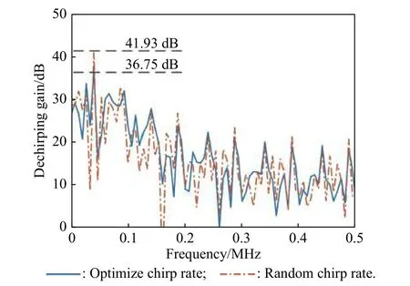
Fig.4 Output signals after dechirping
Based on the VCR-LFM-BPSK with optimized chirp rates,the phase codes can be obtained by the optimization in (15).The formulation in (15) is a performance tradeoff problem,i.e.,the higher the value ofw,the higher the autocorrelation PSL and the lower the spectral peak.Specially,withw=1,only the spectrum ability is optimized.In this case,the spectrums obtained by optimized and random codes are presented in Fig.5.As shown,the spectral peak value for the optimized phase codes is 5.22 dB less than that for the random codes,which verifies the effectiveness of the optimization in suppressing the spectral peak.
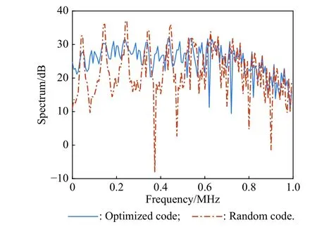
Fig.5 Spectrums of the optimized and random phase codes
Similarly,withw=0,only the autocorrelation ability is optimized.The autocorrelation functions determined by the optimized and random codes are presented in Fig.6.The PSL of the autocorrelation for the optimized and random phase codes are equal to −18.61 dB and −8.435 dB,respectively.These outcomes certify the feasibility of the optimization in suppressing autocorrelation sidelobes.
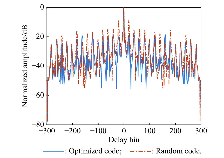
Fig.6 Autocorrelation functions of the optimized and random phase codes
The Pareto curve is given in Fig.7.Withwvarying from 0 to 1,the spectral peak is from 33 dB to 31.9 dB,and autocorrelation PSL is from −18.61 dB to −13.75 dB.As expected,wtrades off the performance of the autocorrelation and spectrum,which is the classical feature of the bi-objective Pareto curve,i.e.,any solution can be a Pareto-optimized point.
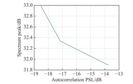
Fig.7 Pareto-optimized curve
4.2 Analysis of the VCR-LFM-BPSK signal from a radar point of view
Since the ambiguity function is an effective tool for analyzing waveform performance,the ambiguity function of the VCR-LFM-PC signal is analyzed in this subsection.
The definition of the baseband LFM-BPSK signal can be rewritten ass(t)=v(t)∗u(t),wherev(t)=rect(t/Tc)ejπKt2,and ∗ denotes the convolution.Therefore,the ambiguity function of the LFM-BPSK waveform can be obtained by χ(τ,fd)=χ1(τ,fd)∗χ2(τ,fd)where χ1(τ,fd) and χ2(τ,fd) are the ambiguity functions ofv(t) andu(t),respectively.Accordingly,the ambiguity function of the LFM-BPSK combines the ambiguity characteristics of the LFM signal and the BPSK signal.The VCR-LFM-BPSK signal is a combination of subpulses from different LFM-BPSK signals with different chirp rates.The smaller the chirp rate,the less LFM feature in the subpulse.Especially,when the chirp rate is 0 GHz/s,the subpulse belongs to BPSK.Therefore,under the same bandwidth,the ambiguity function of the VCR-LFMBPSK is more thumbtack-typed than that of the LFMBPSK.Moreover,the smaller the value of the chirp rate,the more thumbtack-typed the ambiguity function of the VCR-LFM-BPSK signal.
Consider the baseline LFM,BPSK and LFM-BPSK waveforms with the same bandwidthBas the VCR-LFMBPSK.For the LFM signal,the pulse widthTp=15Tc=150μs.For the BPSK signal,the sub-pulse widthTc=1/B,the number of the sub-pulses is 150,and the phase codes are generated randomly.For the LFM-BPSK signal,the bandwidth of the sub-pulse isB,and the rest of parameters are consistent with the VCR-LFM-BPSK.The ambiguity figures are given in Fig.8.As expected,the ambiguity functions are oblique blades and thumbtack typed for LFM and BPSK,respectively.For LFM-BPSK and VCR-LFM-BPSK signals,the ambiguity functions are approximately thumbtack-typed with (2I−1) oblique blades.Moreover,it can be seen in Fig.8(c)−Fig.8(e) that the ambiguity function of the VCR-LFM-BPSK signal becomes closer to thumbtack-typed as the lower bound of chirp rates decreases.
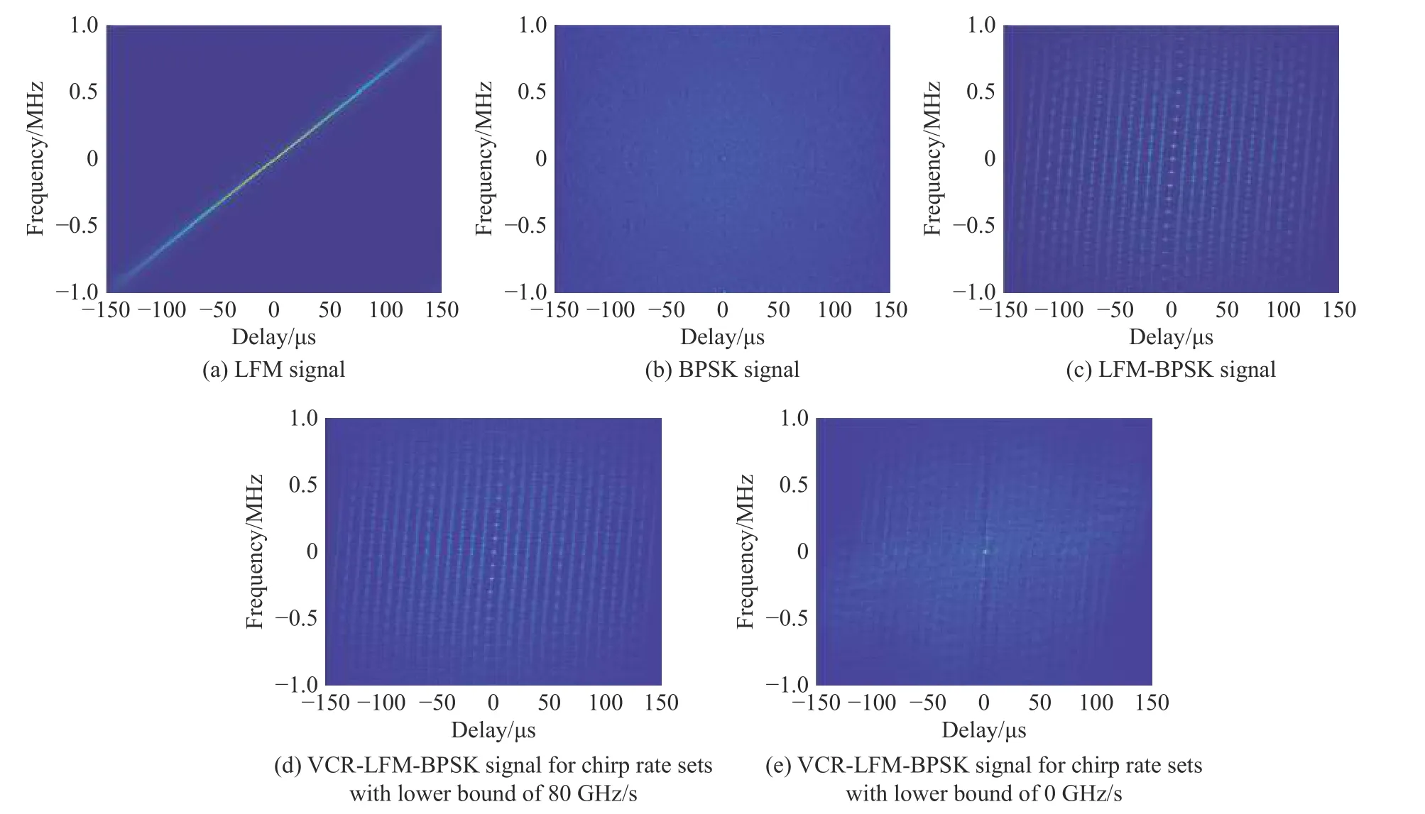
Fig.8 Ambiguity figures
The pulse compressing results under different Doppler shifts are given in Fig.9.As shown,the LFM signal has a low Doppler sensitivity but suffers from the coupling effect of range and velocity.The BPSK signal is sensitive to Doppler frequency shift but solves the problem of range-Doppler coupling.In contrast,both LFM-BPSK and VCR-LFM-BPSK signals reduce the effect of rangevelocity coupling on the LFM and the effect of Doppler sensitivity on the BPSK.As shown in Fig.9,the VCRLFM-BPSK signal has a better sidelobe ability than the LFM-BPSK signal in the case of bothfd=0 MHz andfd=0.1 MHz.Specifically,whenfd=0 MHz,the output peak ratio of mainlobe to sidelobe (RMS) are 17.94 dB and 9.54 dB for VCR-LFM-BPSK and LFM-BPSK,respectively.Whenfd=0.1 MHz,the output RMSs are 13.66 dB and 9.53 dB for VCR-LFM-BPSK and LFMBPSK,respectively.Although the sidelobes of the VCRLFM-BPSK are lower than that of the LFM-BPSK whenfd=0 MHzandfd=0.1 MHz,the loss of the VCR-LFMBPSK caused by the Doppler frequency is higher.To better illustrate the loss,the normalized pulse compressing results of the VCR-LFM-BPSK,including the mainlobe width (MW) (−3 dB),the RMS and the main lobe gain(MG),are given in Table 1.As shown,compared with the case offd=0 MHz,the loss of the MW,RMS and MG for the VCR-LFM-BPSK underfd=0.1 MHz are 0.96×10⁻⁷s,4.28 dB and 1.51 dB,respectively.
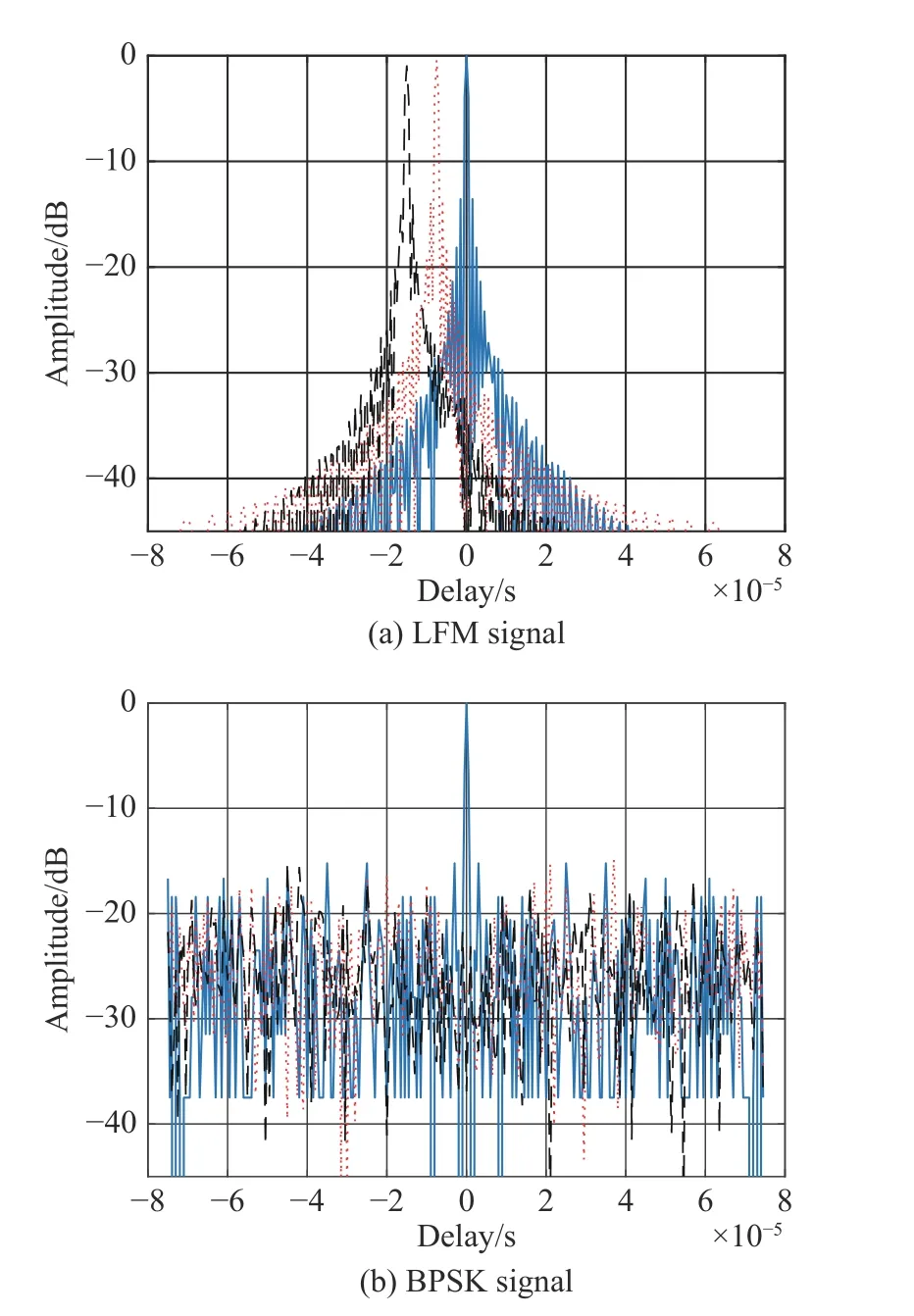
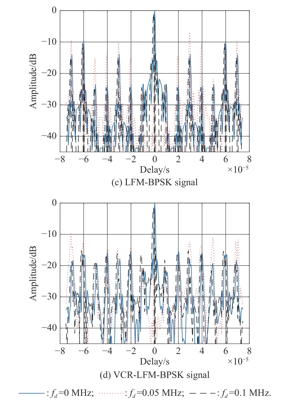
Fig.9 Pulse compressing results

Table 1 Pulse compressing performance under different Doppler shifts
4.3 Analysis of anti-interception performance
In this subsection,we demonstrate the performance of the designed VCR-LFM-BPSK signal in countering advanced interception technologies.
Case 1In this case,based on the assumption that the interception frame in Fig.1 is taken by the interceptor,the anti-interception performance of the VCR-LFMBPSK signal is assessed by comparing with other radar signals.
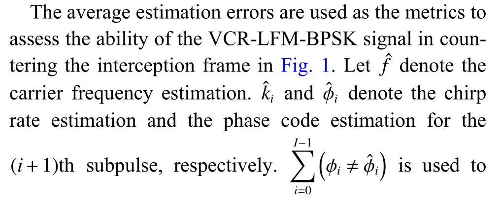
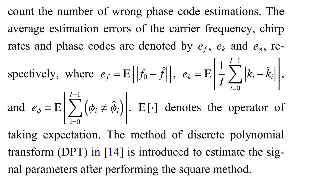
With 500 Monte Carlo experiments,Fig.10 shows the average estimation errors for LFM-BPSK and VCR-LFMBPSK signals with SNR varying from 1 dB to 10 dB.As observed,the estimation error decreases with the increase of SNR,and under the same SNR,the estimation errors for the LFM-BPSK signal are lower than that for the VCR-LFM-BPSK signal.Precisely,when SNR is 4 dB,the estimation errors of the frequency and the chirp rate for the VCR-LFM-BPSK signal are 74 Hz and 37 kHz/s,respectively.In contrast,for the LFM-BPSK signal,the estimation errors of the frequency and the chirp rate are 11 Hz and 4 kHz/s,respectively.Besides,the chirp rate estimation results for the VCR-LFM-BPSK signal are far from the real values even when the curve converges to the stable state.Substituting the chirp rate and frequency estimation results in (3),the phase codes can be reconstructed by multiplying the intercepted signal and the conjugate of the signal in (3).The phase code reconstruction errors with different SNRs are shown in Fig.10 (c).As shown,when SNR is 4 dB,the average estimation error for the LFM-BPSK signal is close to 0 while the average error for the VCR-LFM-BPSK signal is greater than 2.
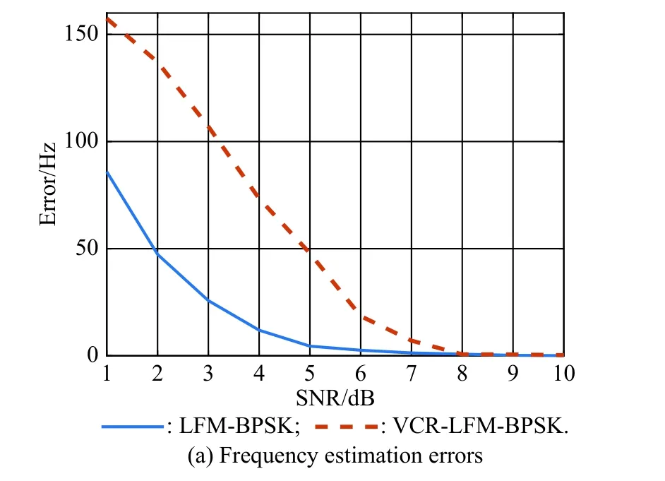
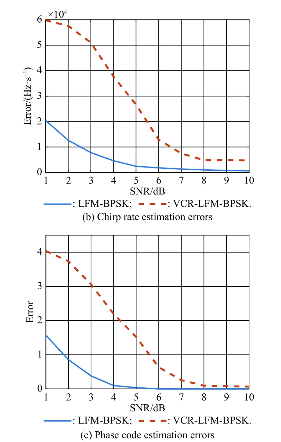
Fig.10 Parameter estimation results for the LFM-BPSK and VCRLFM-BPSK signals with different SNRs
Assuming that the sensed signal can be recognized before being estimated,only the last two steps in the interception frame are used to estimate the parameters of the LFM and BPSK signals.The estimation errors are given in Fig.11 and Fig.12.Obviously,compared with the LFM-BPSK and VCR-LFM-BPSK,the ani-interception performance of the LFM and BPSK signals is poor.
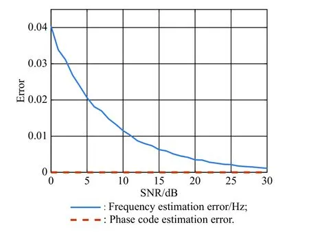
Fig.11 Estimation errors for the BPSK signal
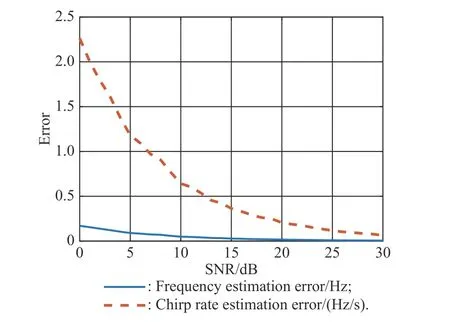
Fig.12 Estimation errors for the LFM signal
All the outcomes above highlight that the VCR-LFMBPSK signal outperforms the traditional radar signals when countering the interception frame in Fig.1.
Case 2Traditional interceptors cannot intercept signals which are submerged in the noise.Since the dechirping method can effectively improve the spectral peak of the signal,it has been widely used in interceptors.In this case,we analyze the ability of the VCR-LFM-BPSK signal in countering the dechirping method.
Assuming that the value ofvfor the dechirping signal ejπνt2sweeps from 0 GHz/s to 100 GHz/s,the dechirping results are given in Fig.13.We can see that the BPSK signal has the best ability of anti-dechirping due to the fewer LFM features.Nevertheless,considering that the BPSK signal can be easily intercepted based on the phase code reconstruction methods,it cannot adapt well to modern ECM environment.Besides,the dechirping gains for the VCR-LFM-BPSK,LFM-BPSK,and LFM signals are 36.75 dB,41.74 dB,and 49.54 dB,respectively.Obviously,the performance of the VCR-LFM-BPSK signal in countering the dechirping method is superior.
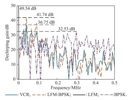
Fig.13 Results of dechirping
5.Conclusions
In this paper,to improve the anti-interception performance of the hybrid waveform,the VCR-LFM-BPSK signal is designed,including the design of signal modulation and that of optimizing signal parameters.Simulation results demonstrate that the designed VCR-LFM-BPSK signal outperforms the traditional radar signals in countering advanced interception technologies.The important contribution of this paper is that a new idea of anti-interception waveform design is proposed,i.e.,designing the waveform by countering specific interception technologies and minimizing the performance of hostile interceptors.Compared with the traditional LPI waveform design based on the definition of the intercept factor,the proposed idea is more adaptable to the modern interception environment where advanced interception technologies are continuously developed.
 Journal of Systems Engineering and Electronics2021年2期
- Journal of Systems Engineering and Electronics的其它文章
- Data-driven evolutionary sampling optimization for expensive problems
- A dual population multi-operator genetic algorithm for flight deck operations scheduling problem
- Observation scheduling problem for AEOS with a comprehensive task clustering
- An improved estimation of distribution algorithm for multi-compartment electric vehicle routing problem
- RFC:a feature selection algorithm for software defect prediction
- A pilot allocation method for multi-cell multi-user massive MIMO system
