Sparse three-dimensional imaging for forward-looking array SAR using spatial continuity
LIU Xiangyang,ZHANG Bingpeng,CAO Wei,and XIE Wenjia
School of Information and Communication,National University of Defense Technology,Shaanxi 710106,China
Abstract: For forward-looking array synthetic aperture radar(FASAR),the scattering intensity of ground scatterers fluctuates greatly since there are kinds of vegetations and topography on the surface of the ground,and thus the signal-to-noise ratio(SNR) of its echo signals corresponding to different vegetations and topography also varies obviously.Owing to the reason known to all,the performance of the sparse reconstruction of compressed sensing (CS) becomes worse in the case of lower SNR,and the quality of the sparse three-dimensional imaging for FASAR would be affected significantly in the practical application.In this paper,the spatial continuity of the ground scatterers is introduced to the sparse recovery algorithm of CS in the threedimensional imaging for FASAR,in which the weighted least square method of the cubic interpolation is used to filter out the bad and isolated scatterer.The simulation results show that the proposed method can realize the sparse three-dimensional imaging of FASAR more effectively in the case of low SNR.
Keywords:forward-looking array synthetic aperture radar(FASAR),sparse three-dimensional imaging,compressed sensing(CS),spatial continuity.
1.Introduction
Forward-looking synthetic aperture radar (FSAR) is very useful in the application of matching guidance with ground features,autonomous navigation and landing of lowaltitude aircraft,and so on.To overcome the difficult problem of lower resolution and left-and-right ambiguity in FSAR,the array antenna technique was introduced to the system firstly by DLR of Germany in 1990s [1]and forward-looking array SAR (FASAR) appeared.Since 2000s,FASAR has received more and more attention all over the world with the rapid development of array technology [2].In early studies,the traditional two-dimensional imaging of the FASAR system was researched firstly,which mainly focused on the imaging algorithm,array antenna design,image enhancement,etc.With the development of studies,multiple continuous two-dimensional image along the flying direction of the airplane not only can be used together to increase the quality of the two-dimensional SAR image,but also to acquire the altitude information of every scatterer in the FSAR image,which is usually called three-dimensional imaging of FASAR.The three-dimensional imaging enlarges the application areas of FASAR greatly,such as geomorphology mapping,geological disasters investigation,natural resources survey,and so on.
The theory and method of matched filtering is firstly applied to FASAR to obtain the three-dimensional image,in which the beamforming of the receiving antenna array is used to accomplish the high resolution of the crosstrack direction,and pulse compression of the transmitting broadband signal is used to obtain the high resolution of the altitude direction,and the high resolution of the along-track direction is obtained by the virtual synthesis of multiple consecutive pulses.Giorgio et al.presented the method of back projection (BP) to realize three-dimensional imaging of FASAR,which has the same shortcoming of a huge amount of computation with the traditional BP algorithm [3].To reduce the amount of computation,the common SAR imaging algorithm,such as range Doppler (RD),chirp scaling,nonlinear chirp scaling (NCS),is applied to the three-dimensional imaging of FASAR [4,5],which achieves the approximate three-dimensional image with acceptable computational complexity.Furtherly,a fast BP algorithm of three-dimensional imaging based on surface prediction is proposed,which makes full use of the characteristics of spatial continuity of the imaging scene and thus improves the imaging efficiency effectively [6].
The imaging algorithms above are all based on the Nyquist sampling in the three-dimensional domain of data collection,which leads to a huge amount of collected signals especially when the resolution in all the three directions is high,such as in the decimeter level.In fact,all the common three-dimensional imaging SAR systems,such as interferometric SAR (InSAR),tomographic SAR(TSAR),curvilinear SAR (CLSAR) and circular SAR(CSAR),collect echo data and achieve the three-dimensional imaging only in a sparse sampling mode to avoid the rapid increase of the data volume of the system.For example,InSAR and TSAR are the sparse sampling systems in the height direction,CLSAR and CSAR are twodimensional sparse sampling systems both in the azimuth direction and the height direction.In addition to some array sparse distribution methods,a two-dimensional sparse sampling scheme both in the across-track direction and the along-track direction for FASAR was proposed,and the corresponding sparse three-dimensional imaging method was studied in [7,8].
Our new researches show that the sparsity of the scattering source of the ground surface appears in the direction of radar line of sight,which can be expressed by the combination of the along-track direction and the altitude direction.Based on the above knowledge,the two-dimensional sparse sampling and the corresponding sparse reconstruction method in the domain of the slant-range frequency and the along-track time for the three-dimensional imaging system of FASAR is presented,which can reduce the amount of data approximately to an order of magnitude compared with the traditional Nyquist sampling methods [9−11].To improve the imaging quality of FASAR in this sparse sampling mode,a new sparse three-dimensional imaging algorithm using the spatial continuity of the ground scatterers is presented,in which the candidate set is selected based on not only the amplitude but also the continuity of space position of the selected scatterers with each other.Meanwhile,the algorithm can also reduce the computational complexity because the search space of sparse reconstruction processing is reduced by using the spatial continuity and the search steps increase.
The remainder of this paper is organized as follows.Section 2 presents the observation model,the echo model of FASAR and the spatial relationship of the ground scatterers.Section 3 gives the sparse recovery model and the sparse recovery algorithm by using the spatial continuity.In Section 4,the performance of the presented method is investigated by simulation experiments.Finally,a brief conclusion is discussed in Section 5.
2.Echo model and signal characteristics
2.1 Sparse observation model of FASAR
The observation configuration of the FASAR system is shown in Fig.1,wherex-axis,y-axis andz-axis denote the along-track,cross-track and altitude direction,respectively.The airplane carrying the FASAR system moves horizontally and uniformly over the observation strip,and the height and the speed of the airplane are expressed asHandv,respectively.The receiving antenna is a uniform and sparse array antenna,and the array surface is perpendicular to the flight direction of the airplane and the altitude direction.The interval,the number of elements,and the array length are marked asd,KandL,respectively.The transmitting antenna is a little and dense array antenna and located below the center of the receiving array antenna with an altitude interval δh.The transmitting beam points to the front and the bottom of the airplane,and the front angle of viewing isθ.In order to keep the number of elements,including receiving elements and transmitting elements,within an acceptable range,the observation strip is divided into multiple sub-strips along the cross-track direction,and the transmitting antenna scans each sub-strip in a time-sharing and on-demand way,where a diagram of the scanning mode with three sub-strips is shown in Fig.1.
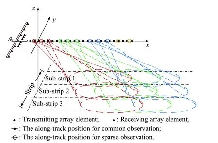
Fig.1 Observation configuration of the forward-looking array SAR system
In the movement of the airplane,the antennas transmit and receive pulse signals at a nonuniform position interval,which corresponds to the sparse sampling in the along-track direction.Here,we assume that the sampling interval Δxbetween the adjacent along-track sampling positions of the airplane is random,which follows the uniform distribution and can be expressed as Δx~U[xmin,xmax],wherexminis the minimum sampling interval which is smaller than the maximum non-ambiguity sampling interval,andxmaxis the maximum sampling interval which determines the sparse sampling rate of the system.Except for the sparse sampling in the along-track direction,the sparse sampling in the slant-range direction is the critical step,since the sparsity of scatterers is closely related to the poor penetration of the millimeter wave to the ground surface in line of sight.However,if the echo signal is sampled directly in the slant-range direction which corresponds to the fast time,the imaging processing of the echo signal would be more complicated.Considering the corresponding relationship between time domain signals and frequency domain signals,the sparse sampling in the frequency domain can also achieve the same results as sparse sampling in the time domain,and thus the stepped frequency signal (SFS) is introduced to the FASAR system to realize the sparse sampling in the slant-range direction.Here,the subpulse signal in SFS with the bandwidth ΔBis applied,where the bandwidth and the chirp rate of every pulse is the same,but the central frequency is different.The central frequency of every pulse is random and follows the uniform distribution,which is represented asfn~U[fc−B/2−ΔB/2,fc+B/2−ΔB/2],wherefcis the central frequency of the system,andBis the total bandwidth of the system.
2.2 Echo model of FASAR
According to the surface scattering model of the ground,it is assumed that the scattering ground is composed of many point scattering sources,and the total echo signal can be expressed as the sum of the scattering signal of these scattering sources,which can be represented as

wherexnandykare the along-track position and the crosstrack position of the receiving elements,xp,ypandzpare the along-track position,cross-track position and altitude position of the point scattering sourcePwhich is a tiny scattering source denoted as dP,σpis the scattering coefficient of the point scattering sourceP,tmis the fast time of themth pulse sampling,wa(·) andwr(·) are the window function of the antenna pattern and the transmitted pulse respectively,cis the speed of the electromagnetic wave,λnis the wave length of thenth transmitting pulse since the central frequency of every pulse is different,γ is the chirp rate,Rtr(xn,yk) is the round-trip distance between the transmitting antenna,the receiving element a nd the scattering source whose position is marked as(xp,yp,zp.As a result,Rtr(xn,yk) can be expressed as

For the echo signal above,pulse compression and beamforming can be applied to process the signal of every pulse firstly,and then the range walk correction method in the time domain is used to pull different range cells of the same scattering source back to the same range cell [7].After the processing above,the echo signal can be represented as

where the function sinc(·) is the sinc function,fkis the normalized wavenumber which is a dimensionless quantity,Rcis the center range of the system,and other parameters are expressed as

After the processing above,the along-track focusing becomes the last and critical step of the three-dimensional imaging of FASAR.Because of the locality property of the sinc function,the signal sequencefor the three-dimensional signal at the positionwhich is in the along-track direction,can be represented as the energy sum of multiple scattering sources as follows:

whereQis the number of scattering sources which is a finite number and will be discussed in the next section.Moreover,the sampling position in the along-track direction is nonuniform and sparse,and how to focus the signalSbecomes the key problem to the sparse three-dimensional imaging,which will be discussed in the next section.
2.3 Spatial characteristics of ground scatterers
Through the analysis of (3) and (5),the position (xp,yp,zp)of the scatterer σpin (5) satisfies the following condition because of the locality property of the sinc function in (3).

Because the cross-track direction is orthogonal to the along-track direction,the following along-track focusing will not improve the resolution of the cross-track direction,so the sub-equation at the bottom of (6) would not affect the distribution of the ground scattering sources.Instead,the number of ground scatterers is closely related to the sub-equation at the top of (5),which is also related to the topography of the ground.Take an along-track signal sequence for example,the blue region represents the possible scattering region calculated by (6),and the green solid line represents the actual ground with scattering sources in the region shown,and other locations in the region will not produce radar echo signals.
Since the resolution of the system is infinite,there are only a few number of scatterers in the ground,which is much less than the sampling number,and the signal model of (5) can be considered as the compressed sensing model.
3.Sparse signal recovery for threedimensional imaging
3.1 Sparse signal model for along-track focusing
Because the position of the scattering source is unknown before the along-track focusing,the ground scatterers cannot be evaluated directly by using (5).One feasible solution scheme for this problem is to search the true position and the scattering intensity of every scattering source during the feasible position space defined by (6),and the search algorithm can correspond to the process of finding the nonzero solution of the following signal model.Equation (5) can be furtherly represented as
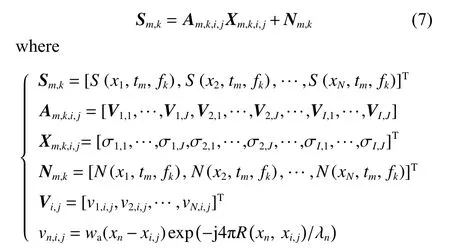
where the subscriptsmandkrepresent the position of the along-track signal on the range cell and the cross-track cell,and the superscript T represents the conjugate transpose.Srepresents the echo signal vector in the alongtrack direction,andNis the noise vector of the receiving signal in the along-track direction.Xrepresents the scattering coefficient of the feasible position space defined by(6),which is the key quantity to be solved for the alongtrack focusing.Here,the feasible position space is divided into a two-dimensional mesh grid on thel-axis ands-axis shown in Fig.2,and the size of each mesh grid is almost the same as the resolution on thel-axis ands-axis.Therefore,Xis composed of the scattering coefficients of these meshes arranged in the order of firsts-axis and thenl-axis.According to the analysis in the previous section,Xshould be sparse because there are no scatterers in most position of the feasible position space.Ais anN×L(L=I×J) dimensional matrix defined by (7).It is shown that the correlation coefficient of any two column vectors inAis relatively small when the size of these meshes in Fig.2 is appropriately selected [8].
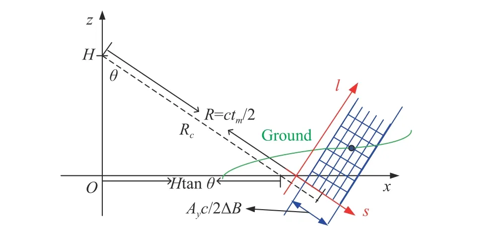
Fig.2 Diagram of space position of ground scatterers
According to the analysis above,it can be concluded that the model and the condition of (7) is very similar to the compressed sensing model.To solve (7) conveniently,it is transformed into a compressed sensing model below.

where the positive parameter ζ is an estimate of the noise level of the echo signal.Here the subscript is omitted for simplicity.
3.2 Sparse recovery algorithm using spatial continuity
The signal model in (8) is a standard compressed sensing model,and many algorithms can be used to solve this equation,such as orthogonal matching pursuit (OMP),subspace pursuit (SP),basis pursuit de-noising (BPDN),and so on.It should be noted that there areM×Ktimes compressed sensing processing for the three-dimensional imaging of FASAR with theM×N×K-dimensional echo signals,so the compression sensing algorithm with low computational complexity should be preferred firstly,especially the greedy compressed sensing algorithm.Moreover,the signal-to-noise ratio (SNR) of theseM×Kcompressed sensing signals varies greatly because the scattering intensity of the ground scatterers fluctuates greatly with the change of vegetation and topography.However,the greedy compressed sensing algorithm has a poor performance in low SNR cases,which may significantly affect the quality of the three-dimensional image.Considering the above factors,the greedy compressed sensing algorithm is improved by using the following two phenomena.Firstly,the scattering source with higher energy can be recovered more accurately with higher probability and priority in the greedy sparse recovery,which has been validated by the way of only recovering the strong scattering source and discarding the weak scattering source in[8].Secondly,the sparse solution for any sparse signal corresponds to a small piece of the ground in Fig.2,and the position of the sparse solution on the ground is continuous and can be approximately described by a spline curve,which can be introduced into the sparse signal reconstruction algorithm to improve the reconstruction performance in the case of low SNR.As a result,the improved sparse reconstruction algorithm using the spatial continuity can be stated as follows.
Step 1Initialize the residualr0=S,the set of selected variablesthe measurement matrixthe detection thresholdTf,the iteration stepLstep,the maximum number of iterationsImax,and the iteration counteri=1.
Step 2Calculate the inner productgiof the residualri−1and the column vector of the measurement matrixwhere
Step 3Ingi,find the largestLstepelement which is larger than the thresholdTfand its indices Ωi.There may not be enough elements to satisfy this condition,and if Ωiis empty,go to Step 8.
Step 4Update the index set Γi=Γi−1∪Ωi.Map the element of the set Γiinto the two-dimensional space of the range direction and the slant-range direction,so the relative range position setWand the relative slant-range position setVof the set Γiare derived.
Step 5If the number of unique elements of the setVis greater than 4,fit the position relation of the slantrange position setVand the range position setWwith a cubic spline functionW=f(V).Then,select the set Ψiwhich is composed of the outliers that the position of the elements does not fall near the cubic spline functionW=f(V),and update the index set Γi=Γi−Ψi.
Step 6The approximate solution of (7) can be calculated by a least squares method,whereAlso,update the new residualri=S−Γi Xiand increase the iteration counteri=i+1.
Step 7return to Step 2,otherwise to the next step.
Step 8Output the sparse solutionXiand the residualri.
The main difference between this algorithm and the common greedy compressed sensing algorithm,such as OMP,SP,compressive sampling matching pursuit(CoSaMP),is that the positional relationship of the candidate elements is furtherly used by cubic interpolation to filter out the bad and isolated elements in Step 5.Moreover,the weighted least square method can be used in the cubic interpolation fitting,in which the greater the amplitude of the candidate elements,the greater the weight.Compared with the method in [8],the detection threshold of this method can be lower,and more effective elements will be recovered.
4.Simulation experiments
In this section,the feasibility of this method for the threedimensional imaging of FASAR are verified by simulation experiments.The main parameters used for the simulation are listed in Table 1.For the simulation of echoes,the flight length of the airplane is about 80 m,the adjacent pulse interval obeys the uniform distribution [0.02,0.18],which corresponds to the sparse sampling ratio of 1/10 related to the Nyquist sampling in the along-track direction.The SNR of the echo is 3 dB.The detection threshold is 16 dB,which is 6 dB lower than the previous method,and the value of iteration stepLstepis 2.
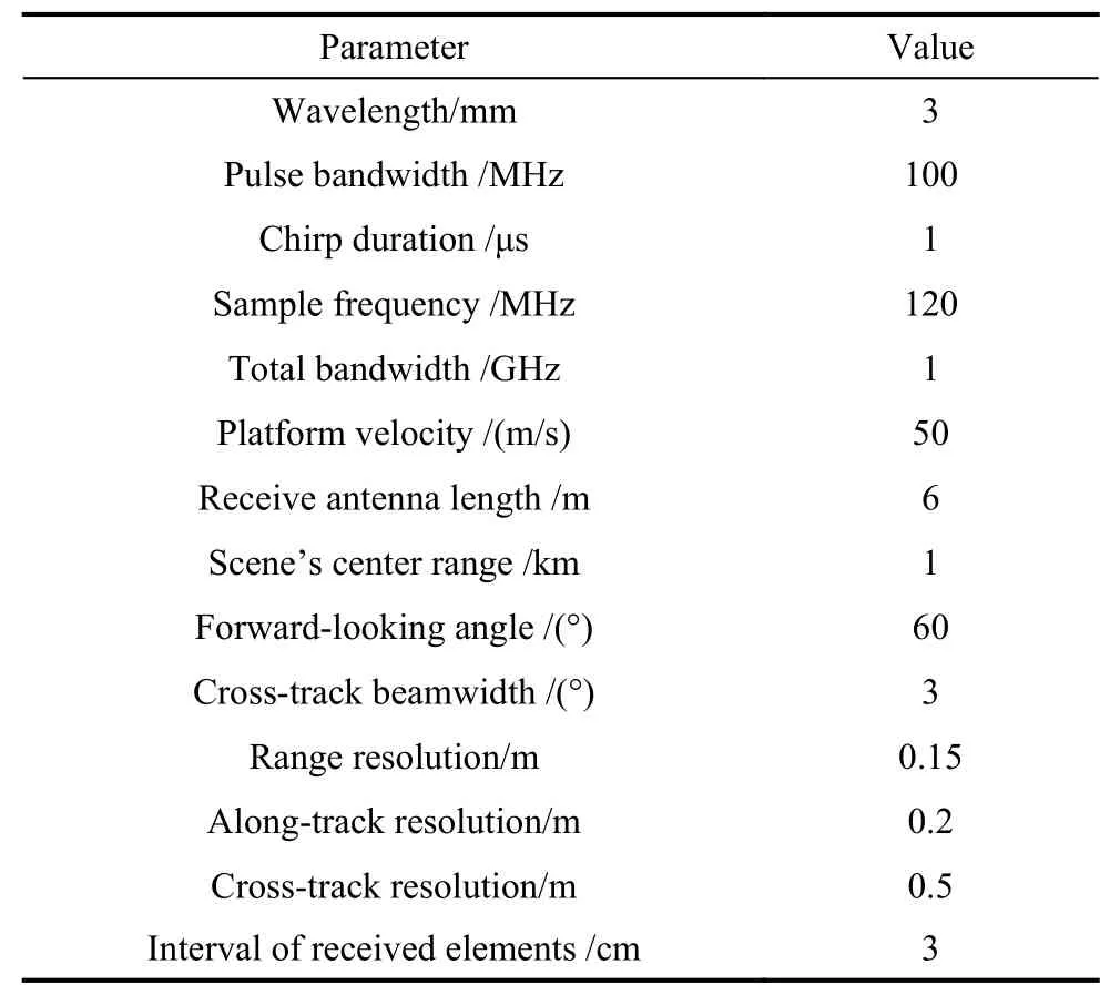
Table 1 Simulation parameters for FASAR system
4.1 Performance comparison and analysis
The recovery performance of our method is compared with the methods of OMP and CoSaMP,where the sparsity of the sparse signal is 10 and other parameters are the same as the parameters of the FASAR system above.Since the coefficient of the sparse signal is random and the number of coefficients is quite small,the correct estimation of the position of all the coefficients is quite difficult,and partial error estimation of the weak coefficient only leads to a lower loss of SNR of the recovery signal.Therefore,partial recovery of the sparse signal is introduced to assess the recovery performance.For example,60% successful recovery is defined as follows:if the position of the nonzero elements in the recovery coefficient vector,whose sparsity is just 60% of the sparsity of the true signal,completely falls in the position of the nonzero elements of the true signal,the signal recovery of the compressed sensing method is considered as effective and successful.According to the evaluation criteria above,the probability of 60% successful recovery of multiple compressed sensing methods is compared with each other,and the probability of our method presented in this paper is higher than the probability of the OMP and CoSaMP methods especially when the SNR is lower than 0 dB,which is shown in Fig.3.
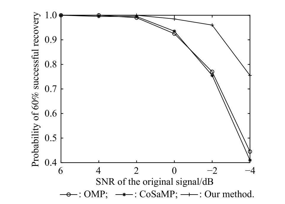
Fig.3 Probability of successful recovery of multiple methods
Moreover,the relationship of the SNR of the recovery signal,the SNR of the original signal and the sparsity of the recovery signal is simulated,which is shown in Fig.4.The SNR of the recovery signal is calculated by the ratio of the original signal without noise and the recovery error which is the difference of the recovery signal and the original signal without noise.Since the probability of successful recovery is related to the SNR of the original signal and the given sparsity,the SNR of the recovery signal is also related to the two factors.There are three results that can be concluded by Fig.4.First,the SNR of the recovery signal decreases with the decrease of the SNR of the original signal.Second,when the SNR of the original signal is relatively high,which is higher than 0 dB in Fig.4,the SNR of the recovery signal increases with the increase of the sparsity,which is because the recovery algorithm has a high recovery probability in the case of the given sparsity.Third,as the SNR of the original signal continues to decline,the recovery probability of the method with a higher sparsity declines more fast,and the SNR of the recovery signal with a higher sparsity is even lower than that with a lower sparsity.
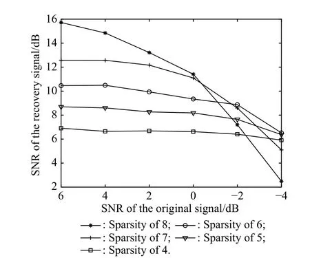
Fig.4 SNR of the recovery signal of our method
Simulation experiments also show that the computation complexity of the presented method will not significantly increase because the complexity of the cubic interpolation which is introduced to our method is much lower than that of the approximate solution of signal recovery in the intermediate steps.Also,the iteration step can be no longer one,and the computation complexity will decrease correspondingly.However,the probability of successful recovery may decrease with the increase of the iteration step,and a moderate result is that the iteration step is less than 1/5 of the sparsity.
4.2 Three-dimensional imaging of FASAR
The three-dimensional imaging results of the horizontal ground is shown in Fig.5,where the color of the scatterers in Fig.5 represents the relative scattering intensity of these scatterers.Also,the mean value of the height error is 0.003 m,the variance of the height error is 0.083 m,which do not exceed the quantized interval of the height direction corresponding to 0.2 m.The above results show that the method in this paper can accurately achieve the three-dimensional imaging of the horizontal ground.
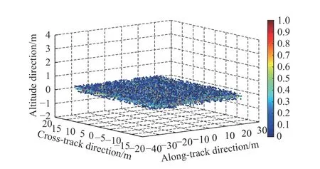
Fig.5 Three-dimensional image of horizontal ground
This method is furtherly validated by the three-dimensional imaging results in the case of undulating terrain,where a symmetrical mountain with a height of 10 m and no layover is selected.The three-dimensional imaging results of the simulated mountain is shown in Fig.6,where the mean value of the height error is 0.004 m,and the variance of the height error is 0.102 m which is larger than the error of the horizontal ground but not exceeds the quantized interval of the height direction.Compared with the method in [8],more than 20% scatterers will be detected with the lower threshold of this method when the terrain is estimated correctly.

Fig.6 Three-dimensional image of simulated mountain
5.Conclusions
For the three-dimensional imaging of FASAR,the Nyquist sampling in the whole data domain will result in a huge amount of data especially when the resolution in all the three directions is high,and thus the sparse sampling is of great value to the system implementation.However,the sparse sampling leads to the performance degradation of signal recovery,especially in the case of low SNR,which is very common for the scattering intensity change of the observation scene.In this paper,the prior information that the sparse signal in a higher dimensional space is continuous is introduced to the sparse signal recovery of the along-track focusing.The use of this feature can effectively improve the quality of the signal recovery of the compressed sensing.Using this method,the quality of sparse three-dimensional imaging of FASAR is improved in low SNR cases.The experimental results show that the proposed method can effectively realize the sparse threedimensional imaging of FASAR even if the SNR is only 0 dB.
 Journal of Systems Engineering and Electronics2021年2期
- Journal of Systems Engineering and Electronics的其它文章
- Data-driven evolutionary sampling optimization for expensive problems
- A dual population multi-operator genetic algorithm for flight deck operations scheduling problem
- Observation scheduling problem for AEOS with a comprehensive task clustering
- An improved estimation of distribution algorithm for multi-compartment electric vehicle routing problem
- VCR-LFM-BPSK signal design for countering advanced interception technologies
- RFC:a feature selection algorithm for software defect prediction
