Generalized Parallel Coprime Array for Two-Dimensional DOA Estimation:A Perspective from Maximizing Degree of Freedom
Luo Chen,Xinping Lin,Beizuo Zhu,*,Xiaofei Zhang
1 College of Electronic Information Engineering,Nanjing University of Aeronautics and Astronautics,Nanjing 211106,China
2 Key Laboratory of Dynamic Cognitive System of Electromagnetic Spectrum Space(Nanjing University of Aeronautics and Astronautics),Ministry of Industry and Information Technology,Nanjing 211106,China
3 The 28th Research Institute of China Electronics Technology Group Corporation,Nanjing 210007,China
Abstract:Parallel arrays with coprime subarrays have shown its potential advantages for two dimensional direction of arrival (DOA) estimation.In this paper,by introducing two flexible coprime factors to enlarge the inter-element spacing of parallel uniform subarrays,we propose a generalized parallel coprime array (GPCA) geometry.The proposed geometry enjoys flexible array layouts by the coprime factors and enables to extend the array aperture to achieve great improvement of estimation performance.Meanwhile,we verify that GPCA always can obtain M2 degrees of freedom (DOFs) in co-array domain via 2M sensors after optimization,which outperforms sparse parallel array geometries,such as parallel coprime array(PCA)and parallel augmented coprime array(PACA),and is the same as parallel nested array(PNA)with extended aperture.The superiority of GPCA geometry has been proved by numerical simulations with sparse representation methods.
Keywords:direction of arrival estimation;generalized parallel coprime array;degrees of freedom;array aperture;coprime factors
I.INTRODUCTION
Two-dimensional (2D) direction of arrival (DOA) estimation has attracted amounts of attention due to the applications in various engineering fields,such as wireless communications,radar,navigation and sonar[1–5].Conventional 2D DOA estimation methods,such as multiple signal classification (MUSIC) algorithm [6]and estimating signal parameters via rotational invariance techniques (ESPRIT) algorithm [7],mainly focus on uniform array geometries like parallel uniform linear array (PULA) [8],uniform planar array(UPA)[9]and L-shaped uniform linear array[10].Specially,among these arrays,the PULA shows its advantage in pairing match of DOAs.However,the adjacent sensors of ULA geometries are required to spaced less than or equal to half wavelength to avoid spatial aliasing,which leads to the limited degrees of freedom(DOFs)and affects the DOA estimation performance.Nowadays,non-uniform arrays,such as minimum redundancy array (MRA) [11],minimum holes array(MHA) [12],coprime array (CA) [13]and nested array(NA)[14],have aroused great attention due to the ability to achieve large DOFs and array aperture in coarray domain.Among these arrays,MRA and MHA have the drawback of lacking the closed-form expression for sensor positions,which limit its engineering applications.Between NA and CA,the NA has enhanced DOFs,whereas,the CA enjoys extended array aperture.
In [15],a parallel nested array (PNA) geometry is proposed for 2D DOA estimation.By vectorizing the cross covariance matrix(CCM)of received signals between the two parallel nested subarrays,the paired 2D DOA estimates of PNA are achieved through 1D DOA estimation methods,such as 1D sparse representation(SR) [16,17].Unfortunately,the PNA has a dense subarray,which degrade the estimation accuracy because of the small aperture.To extend the array aperture greatly,in [18]and [19],parallel coprime array(PCA)and parallel augment coprime array(PACA)are designed,where coprime subarrays are parallel placed.Consequently,the PCA and PACA enjoy the improved DOA estimation performance compared to PNA due to the extended aperture.However,from the perspective of obtaining largest DOFs for parallel arrays geometries,if the number of sensors are even,only the PNA can always achieve optimalM2DOFs in co-array domain via 2Mantennas.
Inspired by the aforementioned arrays,in this paper,we propose a generalized parallel coprime array(GPCA)geometry,where two flexible coprime factors are introduced to enlarge the inter-element spacing of the parallel uniform subarrays.Different from the PCA and PACA,the subarrays of GPCA have the same number of sensors and just the inter-element spacing are coprime.For any given factor,we can verify that GPCA always has optimal DOFs and extended array aperture compared to PNA,PCA and PACA after optimization.Furthermore,we have derived the range of consecutive DOFs of GPCA in co-array domain.As a result,by utilizing the 1D SR based methods,the paired 2D DOA estimates can be obtained with unambiguous and low complexity.
To be more explicit,the main contributions of this paper can be concluded as follows:
1) We propose the GPCA geometry.Among aforementioned parallel arrays,the GPCA enables to achieve the optimal DOFs as PNA because of the same number of sensors for subarrays.Meanwhile,inspired by PCA and PACA,the coprime inter-element spacing of parallel subarrays for GPCA are designed,which contributes to the extended aperture.Overall,GPCA combines the advantages of PNA,PCA and PACA.Consequently,the GPCA has the better estimation performance.
2) We derive the range of consecutive DOFs of GPCA in co-array domain.Therefore,the paired 2D DOA estimates can be achieved by 1D SR based methods with unambiguous and low complexity.
3) GPCA allows flexible array layouts by the coprime factors and both of the PULA [8],PNA [15]and PACA [19]geometries can be interpreted as special cases of the GPCA.
Notations:We use lower-case (upper-case) bold characters to denote vectors (matrix).(·)Tand (·)Hdenote the transpose and the conjugate transpose,respectively.E(·) is the statistical expectation operator.⊗denotes the Kronecker product.☉denotes the Khatri-Rao product.vec(·) denotes the operation of vectorization.diag(·)stands for a diagonal matrix that employs the elements of the vector as its diagonal elements.
II.PRELIMINARIES
In this section,we firstly provide the signal model of parallel arrays,and then we give the expression of virtual array which is produced by physical array in coarray domain.
2.1 Signal Model
Figure1 shows the prototype of the parallel arrays geometries,which consists of two parallel uniform linear arrays (ULAs) with parallel distance beingd,whered=λ/2 andλis the half-wavelength of electromagnetic wave.The ULA arranged along the Y-axis is referred as subarray 1 and another is referred as subarray 2.The number of sensors of subarray 1 and subarray 2 areMandN,respectively.
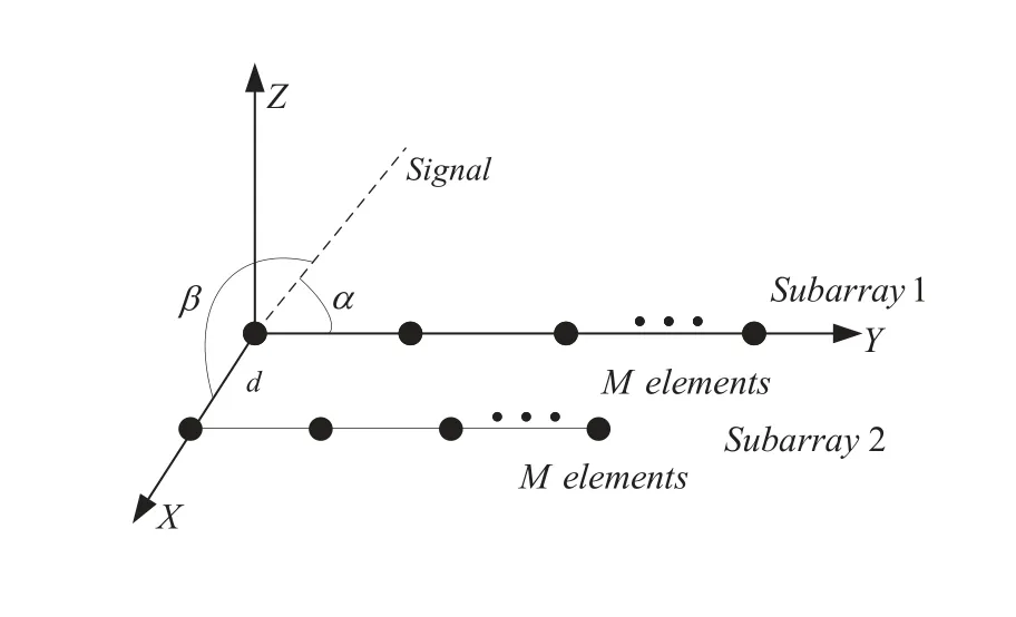
Figure1.The parallel arrays geometries.
Given locations set SM={dm,1,dm,2,···,dm,M}and SN={dn,1,dn,2,···,dn,N}.Consequently,the sensor positions of subarray 1 and subarray 2 in the Cartesian coordinate system can be expressed as

Assume that there areKfar-field narrow-band uncorrelated signals impinging on the parallel arrays with real DOAs(αk,βk),k=1,2,···,K,whereαkis the angle between the wave line and Y-axis,βkis the angle between the wave line and X-axis.
Therefore,the outputs of the two subarrays can be expressed as[20]

where s(t)=[s1(t),s2(t),···,sK(t)]Tis the signal vector.n1(t) and n2(t) are the additive Gaussian white noise vectors with varianceσ2nand mean zero.t=1,2,···,J,whereJis the total number of snapshots.A1=[a1(α1),a1(α2),···,a1(αK)]is the direction matrix of subarray 1,whosek-th column is

A2Φ denotes the direction matrix of subarray 2,where Φ=diag(e−jπcosβ1,···,e−jπcosβK)is a diagonal matrix and A2=[a2(α1),a2(α2),···,a2(αK)]whosek-th column is

According to Eq.(3)and Eq.(4),the CCM between the received signals is[21]

where Rs=diag(σ21,σ22,···,σ2K) andσ2kis the average power of thek-th stationary signal.In practice,CCM of the signals with finite number of snapshots is obtained by[22]

2.2 Vectorization of the CCM

whereη=ΦRs=[e−jπcosβ1σ21,···,e−jπcosβKσ2K]Tand A=A∗1☉A2=[a∗1(α1)⊗a2(α1),a∗1(α2)⊗a2(α2)···,a∗1(αK)⊗a2(αK)].
Definition 1.(Cross Difference co-array):Given specific linear arrays with N and M elements,whose sensor locations set areSN={dn,1,dn,2,···,dn,N}andSM={dm,1,dm,2,···,dm,M},respectively.The cross difference co-array can be defined as[26]

From Eq.(9),note that the elements ofk-th column of A,i.e.a∗1(αk)⊗a2(αk),which enjoys the forme−j(dn,i−dm,q)2πcosαk/λ,wheredn,i ∈SN,dm,q ∈SM,i=1,2,···,Nandq=1,2,···,M.Base on Definition 1,A can be regarded as the direction matrix of a cross difference co-array along the Y-axis,whose sensor locations set is presented as

The direction matrix A only depends on onedimensional angle,i.e.α,which can greatly reduce the complexity for DOA estimation through SR based method shown in section IV.
Definition 2.(degrees of freedom):For a physical sparse array,the DOFs is defined as the cardinality of the cross difference co-arrayS[27].
Remark 1.Usually,conventional DOA estimation methods focus on PULA configuration,which means that M=N andSM={0,d,···,(M −1)d},SN={0,d,···,(N−1)d}for the Figure3.However,the adjacent sensors of PULA geometry are required to spaced less than or equal to half wavelength,which leads to the small DOFs and affects the DOA estimation performance.
III.GENERALIZED PARALLEL COPRIME ARRAY
To extend the array aperture and achieve large DOFs in co-array domain,some sparse parallel array configurations are proposed in [15],[18]and [19].In this section,we firstly review these configurations.Subsequently,we present the proposed GPCA configuration and derive the properties of its cross difference co-array.Finally,we compare GPCA with the existing sparse parallel arrays.
3.1 Review
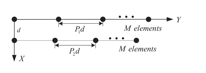
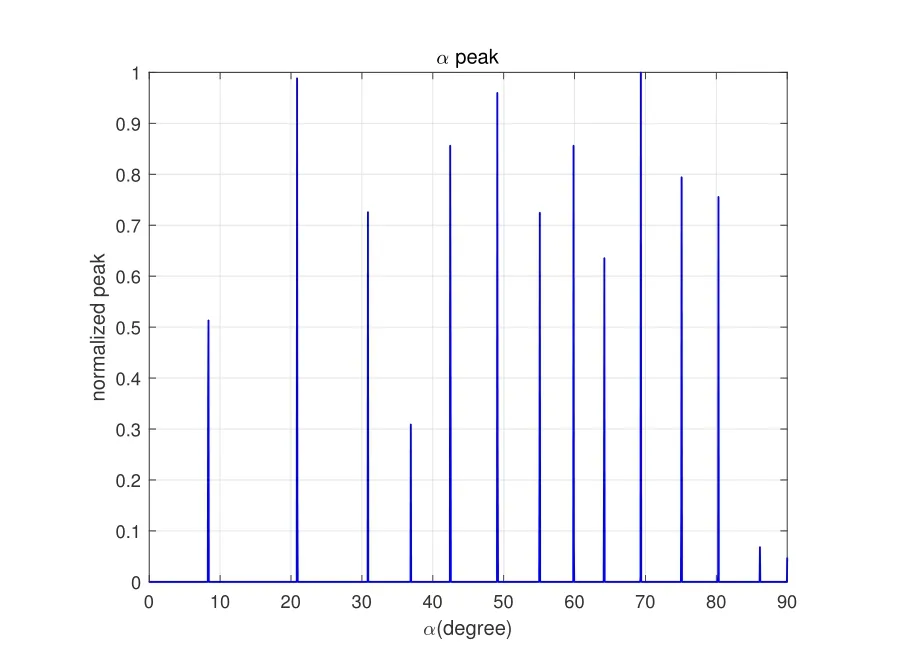
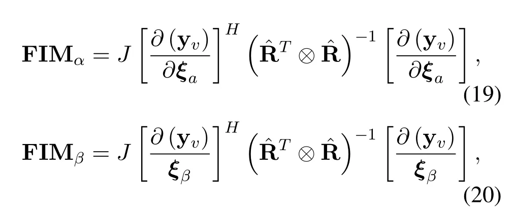
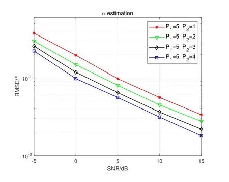
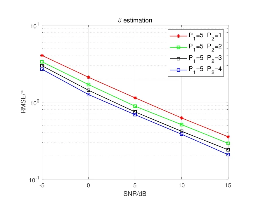
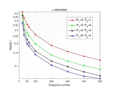
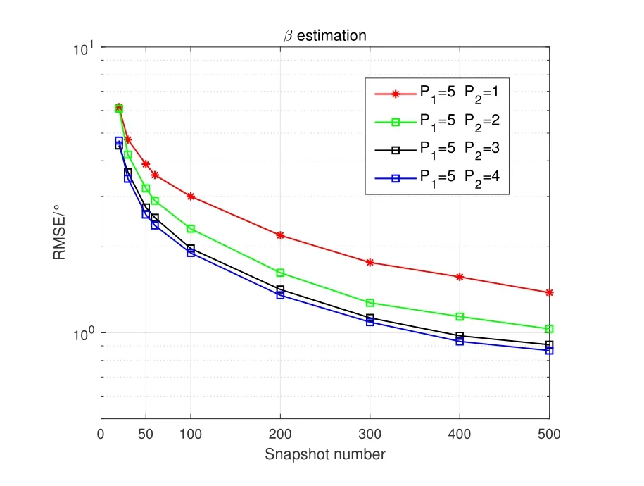
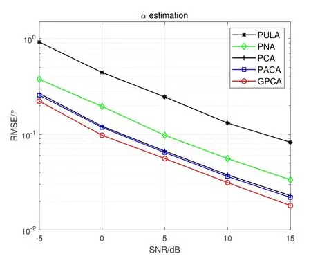
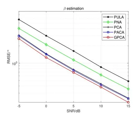
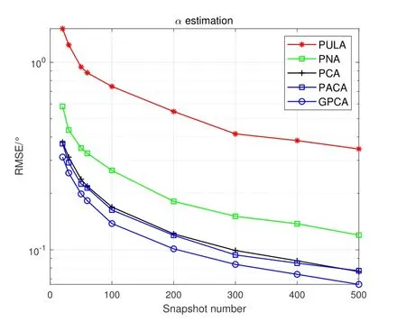
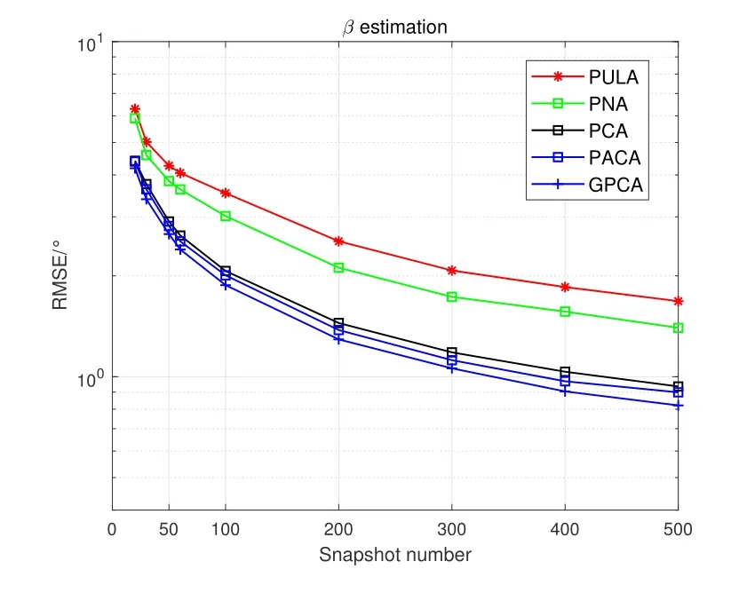
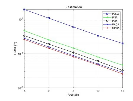
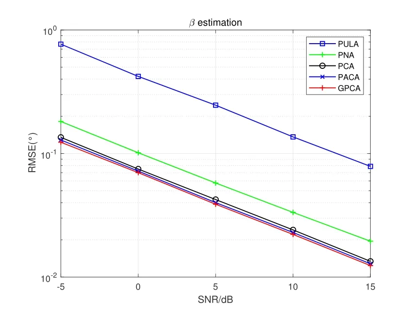
Figure2 shows the prototype of sparse parallel arrays in the platform,including PNA [15],PCA [18]and PACA[19].The subarrays of PNA both haveMelements with spacingMdandd,respectively.For PCA and PACA,they consist of two coprime subarrays,which are extracted from coprime array[13]and augmented coprime array[28].Specifically,subarray 1 of PCA hasMsensors with element spacing withNd,subarray 2 hasNsensors with element spacing withMd,whereMandNare coprime.For PACA,subarray 1 has 2M −1 sensors with element spacing withNd,subarray 2 hasNsensors with element spacing withMd,whereMandNare coprime and satisfyM Base on Eq.(10) and Eq.(11),we can obtain the expressions of cross difference co-array produced by these arrays,denotes as DPNA,SPNA,DPCA,SPCA,DPACAand SPACA.According to [15],SPNAcontainsM2unique lags,which means that the PNA enables to achieveM2DOFs via 2Msensors.However,the PNA has a dense subarray,which degrade the estimation accuracy due to the small aperture.The PCA and PACA have large aperture because of coprime element spacing.Similarly,the PCA configuration shown in Figure2(b) and the PACA configuration shown in Figure2(c)can achieveMNand(2M −1)NDOFs viaM+Nand 2M −1+Nsensors,respectively.Whereas,it is obvious that when the number of total sensors of parallel arrays are even,the DOFs achieved by PCA and PACA are less than or equal to PNA due to the coprimality betweenMandN. Figure2.The sparse parallel arrays geometries (a) PNA(b)PCA(c)PACA. Remark 2.In addition to the above sparse parallel arrays,some sparse parallel arrays have been proposed.In [29,30],The configuration of two parallel nested arrays was applied to improve aperture and achievable DOFs,However,the two nested parallel array proposed in the above literature directly places the nested linear array [14]in parallel,Similar to PNA,the configuration optimization problem of the array has not been considered.And as introduced in introduction,compared nested array with nested array,under the same total array elements,there are disadvantages in array aperture and mutual coupling.In[31],the author proposes a symmetric co-prime parallel array,and obtains a large number of DOFs in perspective of sum and difference co-array.However,The symmetric co-prime parallel array does not maximize the DOF of the double parallel array difference array with a fixed number of elements. Overall,the aforementioned sparse parallel arrays exist advantages and drawbacks.Inspired by these arrays,from the perspective of obtaining optimal DOFs and getting extended aperture,we propose the GPCA configuration. In this section,by introducing two flexible coprime factors(i.e.P1andP2)to enlarge the element spacing of PULA,we propose the GPCA configuration.Figure3 shows the prototype of GPCA in the platform,where subarray 1 of GPCA hasMelements with spacingP1dand subarray 2 hasMelements with spacingP2d.Base on the signal model described in section II, Figure3.GPCA geometry in the platform. we can obtain the sensor locations set of cross difference co-array which is generated by GPCA from Eq.(11),denoted as where SP1={0d,P1d,···,(M −1)P1d}and SP2={0d,P2d,···,(M −1)P2d}. Remark 3.From Figure3,we can see that,in case of P1=1,P2=1or P1=M,P2=1,GPCA can be regarded as the PULA[8]and PNA[15]configuration,respectively.In addition,when M is odd,let coprime factors P1=M and P2=(M+1)/2,the PACA[19]configuration is constructed.Therefore,both of the PULA,PNA and PACA can be interpreted as special cases of the GPCA.Meanwhile,the GPCA also enjoys more practical array layouts with coprime factors. According to Definition 2,the DOFs of GPCA in co-array domain are determined by calculating the cardinality of SGPCA.To maximize DOFs,we have the following theorem Theorem 1:In case ofP1=M,1≤P2 Proof.Using contradiction to prove this theorem.According to Eq.(12),given two arbitrary lags in SGPCAsatisfyingm2−m1=y2P2d−y1P1dand−=−wherem2,¯m2∈SP2,m1,∈SP1andy1,y2,∈[0,M −1].If the condition thatm2−m1=hold,we have Sincey2− Remark 4.Assume that all the parallel arrays geometries,such as PULA,PNA,PCA,PACA and GPCA,have2M total antennas.As the basic discussion above,only the GPCA and PNA always can reach M2DOFs in co-array domain while the DOFs achieved by PULA,PCA and PACA are less than or equal to M2.Furthermore,compared to PNA,the GPCA avoid the dense subarray configuration,which contributes to the extended array aperture and improved DOA estimation performance. From Eq.(9),we can achieve 2D DOA estimation of GPCA through one dimensional SR based methods[18].However,SR methods require at least a pair of antennas in arrays spaced small than or equal tod,to ensure the unambiguous DOA estimation.Thus,we have the following theorem for SGPCA. Theorem 2:Case 1:ifP1=M,1≤P2 Proof.For case 1,we should prove that whenP1=M,1≤P2 Sincey1∈[0,M −1],we have Eq.(15)can be rewritten as Because 1≤P2 Similarly,we also can prove that the case 2 is established. Overall,the optimal configuration for GPCA with maximum DOFs can be conclude as Table1. Remark 5.From Table1,we know that the flexible coprime factors allow GPCA to achieve maximum DOFs with different array layouts.Furthermore,for SR based DOA estimation methods,with the increase of P1or P2,the extended array aperture will improve the DOA estimation performance (simulation results in section V verify this conclusion). In this section,1D SR based algorithm[18]is utilized to achieve the paired 2D DOA estimates. According to Eq.(9),we construct the discretized sample gridα1,α2···,αD(D >>K)which contains all the interested values of ˆαk.Expand the direction matrix A to a fat dictionary Θ=[a∗1(α1)⊗a2(α1),a∗1(α2)⊗a2(α2)···,a∗1(αD)⊗a2(αD)].Correspondingly,expandηto a taller sparse vectorρ ∈CD×1,whose elements corresponding to the true estimation ofkeep the same with those inη,and the others are all-zero.In this paper,we assume the true DOAs are all on the discretized sampling grid.For the case of the off-grid problem[32,33]that such assumption does not holds,the adaptive matching pursuit method [34]can be applied to update the grid adaptively and reduce errors caused by grid mismatching. Therefore,the desired result ofρcan be expressed as the solution to the following constraint minimization problem[18] where‖·‖1and‖·‖2areℓ1-norm andℓ2-norm,respectively.ξdenotes the regularization parameter.By utilizing the sparse recover tools (e.g.SPGL1 [35]or CVX[36]),then thecan be recovered from(17).By locating the position of the non-zero rows of ˆρ,estimates of(k=1,2,···,K) can be obtained from sample gridα1,α2···,αD.Furthermore,the nonzero rows of ˆρgive the estimation ofη,hence,estimates ofcan be presented as The steps of the SR based algorithm can be concluded as follows: Step 1:obtain the received signals of parallel subarrays x1(t)and x2(t),t=1,2,···,J,whereJis the total number of snapshots. Step 2:construct the virtual received signal r of cross difference co-array as Eq.(9). Step 3:construct the discretized sample gridα1,α2···,αD(D >>K).Subsequently,expand the direction matrix A in (9) to a fat dictionary Θ and meanwhile expandηto a taller sparse vectorρ. Step 4:solve the solution to the constraint minimization problem as Eq.(17) to obtain ˆαk(k=1,2,···,K).According to Eq.(18),obtain the paired(k=1,2,···,K). In this section,discussion of array structures,mutual coupling and Cramer-Rao Bound (CRB) comparison for different arrays are employed to outstand the advantages of GPCA. As the basic discussion above,we know that the GPCA and PNA have the biggest DOFs among the aforementioned parallel arrays in co-array domain.Furthermore,the PNA can be interpreted as a special case of GPCA whenP1=MandP2=1.IfP2>1,the GPCA enjoys the extended array aperture compared to PNA.In array signal processing,both of the DOFs and array aperture will affect the DOA estimation performance. Table1.Optimal configuration for GPCA. According to the Definition 1,when the sensors in subarray 1 and subarray 2 are bothMandP1=M,the total DOFs in GPCA isM2regardless ofP2.However,1≤P2 For comparison,in Table2,we list the performance parameters achieved by parallel arrays with 10 total number of antennas as an example,where GPCA,PULA,PNA,PCA and PACA are included.For GPCA,we consider the case ofP1=M,1≤P2 Table2 shows that GPCA5(5),5(4)enjoys the highest DOFs and biggest array aperture.Moreover,PACA5(5),5(3)and GPCA5(5),5(3)have the same parallel configuration,which verify that we can reconstruct the PACA through GPCA. In order to demonstrate the extended DOFs of the proposed GPCA,DOA estimates for underdetermined case are taken for simulation where 12 uncorrected signals are received by GPCA.Meanwhile,there are only 10 physical sensors which is GPCA5(5),5(4).Figure4 depicts the spectral peaks of SR based algorithm forαestimates where the DOAs of the 12 signals are (α1,β1)=(10°,15°),(α2,β2)=(20°,25°),(α3,β3)=(30°,35°),(α4,β4)=(35°,40°),(α5,βz)=(42°,50°),(α6,β6)=(50°,55°),(α7,β7)=(55°,60°),(α8,β8)=(60°,65°),(α9,β9)=(65°,70°) (α0,β10)=(70°,75°),(α11,β11)=(75°,80°),(α12,β12)=(80°,85°) whereSNR=15dBand snapshotJ=200.According to Figure4,all the 12 peaks correspond to the realαestimates,which proves the superior performance of GPCA in line with the theory.βestimates can thus be obtained by Eq.(18) with no extra pairing operation.However,it is inevitable that as the number of signals increase,the estimation accuracy degrades for underdetermined case. Figure4.α peak estimates for underdetermined case. In practice,the received signal model is affected by mutual coupling,which can be evaluated by coupling leakage (CL) [37].The smaller CL is,the array suffers from lower mutual coupling,which means better array performance.The PULA and PNA incorporate the dense subarray with inter-element spacing of half wavelength,causing severe mutual coupling effects.PCA and PACA solve the problem of the dense subarray.However,compared with the proposed GPCA in this paper,PCA and PACA have the drawbacks of asymmetric sensors or array aperture for the two subarrays. Table3 lists the coupling leakage comparision among different array structures where the total physical sensors are all 8 for different arrays.It is obvously seen that the proposed GPCA enjoys the smallest coupling leakage due to the loose array structure. Cramer-Rao Bound(CRB)is considered as a standard to evaluate the lower bound for a specific array structure.Under the environment that sources are morethan sensors,traditional closed-form CRB expression may not be suitable because the Fisher information matrix can be nonsingular.According to [38],Fisher information matrix is introduced as Table2.Performance parameters comparison of different arrays. Table3.Coupling leakage comparison. In this section,numerical simulations are employed to evaluate the DOA estimation performance for the proposed GPCA configuration.The root mean square error (RMSE) is employed as the performance metric,which can be expressed as whereQis the times of Monte Carlo simulations,andpresent theq-th trial for thek-th theoretical angleαkandβk,respectively.In this paper,Q=500 and we set the total number of physical sensors for parallel arrays as 10.Assume that there areK=2 uncorrected signal with DOAs (α1,β1)=(45°,40°)and(α2,β2)=(55°,50°). As described in Table1,GPCA achieves the maximum DOFs in co-array domain when coprime factors satisfyP1=M,1≤P2 Figure5 and Figure6 depict that with increase of SNR,the RMSE performance of GPCA improve.Furthermore,note that the bigger ofP2is chosen for GPCA (i.e.bigger aperture),the better angle estimation accuracy can be achieved. Figure7 and Figure8 show the angle estimation performance comparison versus snapshot under different values ofP2,whereSNR=0dB.With the increase of the snapshot,the GPCA can achieve the better DOA estimation performance.Moreover,the increase ofP2(i.e.extended aperture) contributes to the improvement of RMSE performance for GPCA. Figure5.RMSE comparison versus SNR under different P2 (α angle). Figure6.RMSE comparison versus SNR under different P2 (β angle). Figure7.RMSE comparison versus snapshot under different P2 (α angle). Figure8.RMSE comparison versus snapshot under different P2 (β angle). In this subsection,the RMSE performance comparison between different arrays is implemented,where GPCA,PULA,PNA,PCA and PACA are included.According to conclusion from Figure5 to Figure8,we know that for a specific array,the extended aperture contributes to the improvement of RMSE performance under the same DOFs.Therefore,combining with Table2,we consider the cases PACA5(3),5(5)and GPCA5(5),5(4)for simulation.Figure9 and Figure10 give the angle estimation performance comparison of different array versusSNR,whereJ=200. Figure9 and Figure10 depict that with the increase ofSNR,the RMSE performance of different array improve.Furthermore,the proposed GPCA enables to achieve the best RMSE performance among these arrays due to the optimal DOFs and extended array aperture.According to Table2,although the PCA configuration has the same aperture as PACA configuration,the smaller DOFs degrade the estimation accuracy.Figure11 and Figure12 show the angle estimation performance comparison versus snapshot under different arrays,whereSNR=0dB.With the increase of the snapshot,the RMSE performance of different array improve.Moreover,the GPCA configuration can achieve the best DOA estimation performance due to the optimal DOFs and biggest aperture. Figure9.RMSE comparison of different arrays versus SNR(α angle). Figure10.RMSE comparison of different arrays versus SNR(β angle). Figure11.RMSE comparison of different arrays versus snapshot(α angle). Figure12.RMSE comparison of different arrays versus snapshot(β angle). Figure13 and Figure14 demonstrate the CRB performance of different array structures,where PULA,PNA,PCA,PACA and GPCA are taken for comparison.Simulation environment is the same as in subsection 6.2. AsSNRincreases,the CRB performance of the array structures all gets improved.Meanwhile,PULA suffers from largest CRB due to the dense subarray and small array aperture.The other sparse arrays significantly improve the CRB performance where PNA has larger CRB than PCA,PACA and GPCA because one subarray in PNA is dense array where sensor spacing is half wavelength.The proposed GPCA achieves the best CRB performance contributed by the optimal DOFs and extended array aperture. Figure13.CRB comparison with different array structures(α angle). Figure14.CRB comparison with different array structures(β angle). In this paper,we propose a GPCA geometry for DOA estimation.By introducing two coprime factors to enlarge the inter-element spacing of parallel uniform subarrays,the GPCA enjoys flexible array layouts and extended array aperture.After optimization,we verity that the GPCA always can achieveM2DOFs via 2Msensors.Furthermore,we derive the range of consecutive DOFs of GPCA in co-array domain.Therefore,the paired 2D DOA estimates can be achieved by 1D sparse representation based method with unambiguous and low complexity.Simulation results testify that the GPCA outperforms the existing sparse parallel array geometries,such as PCA,PNA and PACA.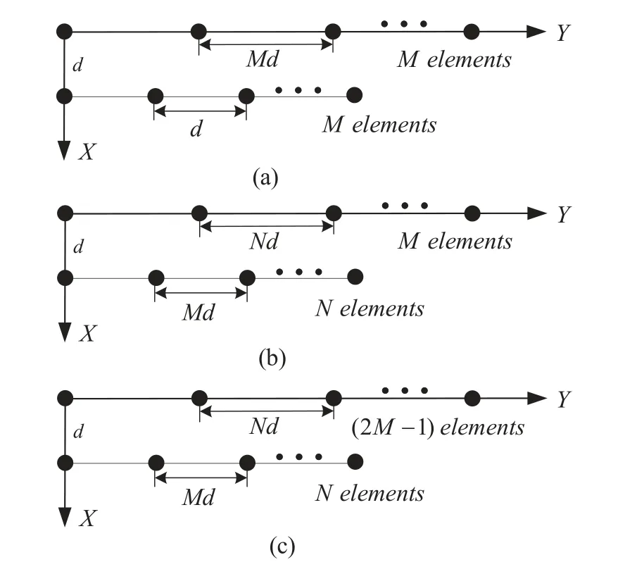
3.2 Generalized Parallel Coprime Array


IV.DOA ESTIMATION


V.PERFORMANCE ANALYSIS
5.1 Discussion of Array Structures

5.2 Mutual Coupling Analysis
5.3 Cramer-Rao Bound Analysis



VI.SIMULATION RESULTS


6.1 RMSE Comparison of GPCA with Different Array Layouts
6.2 RMSE Comparison of Different Parallel Arrays
6.3 CRB Comparison with Different Array Structures
VII.CONCLUSION

