A Robust UWB Array Localization Scheme through Passive Anchor Assistance
Haipeng Lu,Tianyu Wang,Feng Ge,Yuan Shen,*
1 Electronic Engineering Department,Tsinghua University,Beijing 100084,China
2 Beijing National Research Center for Information Science and Technology,Beijing 100084,China
Abstract:Ultra-Wide Bandwidth (UWB) localization based on time of arrival (TOA) and angle of arrival(AOA)has attracted increasing interest owing to its high accuracy and low cost.However,existing localization methods often fail to achieve satisfactory accuracy in realistic environments due to multipath effects and non-line-of-sight (NLOS) propagation.In this paper,we propose a passive anchor assisted localization (PAAL) scheme,where the active anchor obtains TOA/AOA measurements to the agent while the passive anchors capture the signals from the active anchor and agent.The proposed method fully exploits the time-difference-of-arrival(TDOA)information from the measurements at the passive anchors to complement single-anchor joint TOA/AOA localization.The performance limits of the PAAL system are derived as a benchmark via the information inequality.Moreover,we implement the PAAL system on a low-cost UWB platform,which can achieve 20 cm localization accuracy in NLOS environments.
Keywords:ultra-wideband localization;NLOS environments;passive listening;adaptive unscented Kalman filter(UKF)
I.INTRODUCTION
Location-based services are infiltrating all aspects of our lives,such as autonomous vehicles and intelligent manufacture [1–5].Localization technologies based on radio frequency signals such as Bluetooth,Wi-Fi and radio-frequency identification (RFID),has attracted growing attentions from both the academic and industry communities in the recent years[6–8].However,it is difficult for these technologies to achieve sub-meter level localization accuracy in complex and indoor environments.In the past decades,the UWB technology has been introduced to indoor positioning with sub-meter localization[9–11].In comparison with the conventional wireless localization technologies,UWB has many appealing advantages including high time resolutions,low-transmit power,and strong anti-interference ability [11–13].Recent years have also seen studies on the effective allocation of power and spectrum resources for high-accuracy localization[14–17].
Leveraging high time resolution,mostactiveUWB localization methods rely on time-related measurements,such as TOA an TDOA [18,19].TDOAbased localization methods have been widely used in commercial UWB positioning due to high system efficiency,but they require accurate clock synchronization between the anchors[19].In contrast,TOA-based UWB localization uses two-way ranging(TWR)technologies to estimate the distance,which no longer requires clock synchronization between the anchors[20].The key of TWR is to minimize the ranging error caused by the clock offset between different devices.To reduce the ranging error and improve the efficiency in TOA-based localization systems,several improved TWR methods have been proposed,such as doubleside TWR[21],double TWR[22],alternative double-side TWR[23].
On the other hand,passiveranging technologies are also introduced in TOA-based localization systems,which can acquire extra ranging measurements through passive listening [24–26].The authors in[24]proposed an asymmetrical timestamping and passive listening protocol for joint clock synchronization and ranging.In [25]the passive extended alternative double-side alternative TWR is proposed to further mitigate the effects of clock skew.In [26],a unified factor graph-based framework is developed for TOAbased passive localization.In summary,all of these ranging methods focus on mitigating the ranging error caused by clock offsets or improving the efficiency of ranging protocols.
In addition to time-related measurements,wideband arrays can further obtain AOA measurements from UWB signals[27–29].Hence,single-anchor localization (SAL) can be realized by UWB arrays by joint TOA and AOA estimation,which can achieve a positioning accuracy of 20 cm in line-of-sight(LOS)scenarios experimentally[29].Note that the TOA/AOAbased SAL method does not require synchronization between anchors and agents,which significantly reduces the system complexity[29].
Although the SAL method for UWB systems represents a promising high localization accuracy,it cannot perform robustly in realistic environments,where multipath effects and NLOS propagation introduce biases to position-related measurements [29–31].For conventional range-based UWB localization,NLOS identification and mitigation methods are proposed enhance the robustness of localization systems[32–34].However,these learning-based methods require excessive measurement campaigns.Another kind of robust localization method is achieved by appropriately weighing LOS and NLOS measurements [35,36].Moreover,cooperative localization methods are also developed to eliminate the negative effects caused by the NLOS biases[37–39].
In this paper,we propose a robust localization scheme for TOA/AOA-based UWB localization systems.In the proposed scheme,two kinds of anchors are introduced to jointly localize agents,where an active anchor implements SAL and the passive anchors assist localization by TDOA measurements.The main contributions of this paper are summarized as follows.
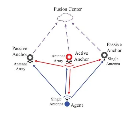
Figure1.System model of the passive anchor assisted localization.
• We propose a passive anchor-assisted localization scheme where the TDOA and clock skews of passive anchors are jointly estimated to complement the TOA/AOA measurement by the active anchor.
• We derive the performance limits of localization accuracy for the proposed localization scheme,in terms of the squared position error bound(SPEB).
• We develop a real-time localization algorithm for PAAL systems,and verify the performance of our method on a low-cost UWB platform.
The rest of this paper is organized as follows.Section II presents the proposed system model.In Section III,the maximum likelihood estimator(MLE)of TDOA is derived and the localization algorithm for PAAL is presented.Section IV derives the performance limits of the proposed method.Experiments and analyses are shown in Section V.The conclusions are drawn in Section VI.
Notations:[·]Tdenotes the transpose of its argument;tr{·}represents the trace of a square matrix;[x]iis the i-th element of the vector x;N(µ,Σ) is the Gaussian distribution with mean vectorµand covariance matrix Σ.
II.SYSTEM MODEL
Consider a system consisting of an agent,an active anchor andNpassive anchors.Among these passive anchors,N1of them are equipped with antenna arrays while others are only equipped with single antennas.The positions of the active anchor and passive anchors are known and denoted by pa∈R2and pc∈RN×2,respectively.The position of the agent is unknown at thek-th measurement and denoted by pk=[xk,yk]T.As shown in Figure1,the agent and the active anchor communicate with each other in the positioning process and all of these signals can be captured by the passive anchors.That is,all passive anchors can obtain the receive timestamps,or the phase difference of arrival if equipped with an antenna array.All measurements from the active anchor and passive anchors are sent to the fusion center for agent localization.
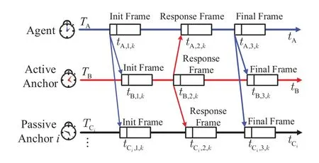
Figure2.Illustration of the round-trip communication at the k-th measurement.
The communication protocol of the proposed system is shown in Figure2,which is based on the roundtrip protocol in [23].In the process ofk-th measurement,the agent first sends an Init Frame to the active anchor.The active anchor then reply a Response Frame after receiving the Init Frame and the agent reply a Final Frame to the active anchor at the end of the round-trip communication.As shown in Figure2,all timestamps when devices receive and transmit signals can be measured.The subscript A denotes the agent,B denotes the active anchor and Cidenotes thei-th passive anchor.Besides,we use the subscriptj ∈{1,2,3}to represent the Init Frame,Response Frame and Final Frame,respectively.For example,tA,1,krepresents the transmit timestamp at thek-th measurement of the Init Frame from the agent.
To facilitate the description,we define the agent as a reference clock in a period,of which the clock skew and initial timeTA=0.DefinekB,kC1,···,kCNas the unknown clock skews compared with the reference clock andTB,TC1,···,TCNas the initial time of anchor and passive anchors,respectively.Since the devices are asynchronous,the measurement error of timestamps is related to both the clock drift error and observation noises.In particular,the relationship between the timestamp observationand its true valuetX,j,kcan be written as

where the subscriptX ∈{A,B,C1,···,CN},TXdenotes the initial timestamp of the deviceX,kXis the clock skew andnX,j,kdenotes the additive white noise in the time observation.Then,the time period of the deviceXis given by

wherej ∈{1,2}.We defineσ2rXas the variance of the timestamp noise in receiving process andσ2tXas that in transmitting process.Note thatσ2rXis usually greater thanσ2tXduring the time measurement process.When the anchor equipped with an antenna array ofMelements can also measure arrival phases from the channel impulse response (CIR) [29],the raw phase observation from the antennamat thek-th measurement is given by

where the subscriptXa∈{B,C1,···CN1},ϕXa,r,kdenotes the reference phase at the center of the array,fcis the carrier frequency of the signal,cis the speed of light,dXa,mis the constant distance from the antenna to the center of the array,θXa,kis the AOA,αXa,mis the reference angle of the antennamandnXa,m,k ~N(0,σ2p)denotes the additive white Gaussian noise in the phase measurements.
In summary,we denote all measurements at thek-th measurement as zk=[zτ,k,zϕ,k]T,where
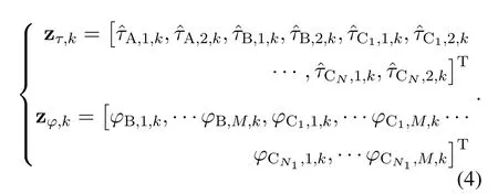
After thek-th measurement,the fusion center can obtain zkfrom all anchors to localize the agent.Let xk=[xk,yk,vx,k,vy,k]Tbe the agent state vector at thek-th measurement.The agent’s mobility is assumed as constant velocity motion and the prior information of velocity is given by v0~N(0,P0),in which P0denotes the covariance matrix of the initial velocity.Therefore,the prediction equation is given by

where Φkis the state transition matrix of constant velocity motion and wkis the process noise with variance Qk.
III.LOCALIZATION ALGORITHM
In this section,we derive a closed-form MLE for the TDOA between the agent and the active anchor to the passive anchor.Then we design a real-time localization algorithm for PAAL to fuse the ranging and AOA measurements from the active anchor and passive anchors.
3.1 Passive Ranging Algorithm
We first propose a MLE to obtain the TDOA from passive anchors.Since TDOA estimations from different passive anchors are similar,we take the case ofN=1 as an example.Define the unknown parameters as Θτ,k=[τA,1,k,τA,2,k,kB,kCi,Tf,k,∆TCi,k]TwhereτA,1,kandτA,2,kare actual time periods of the agent,kBandkCiare the clock skews of the active anchor and the passive anchor,Tf,kis TOA from the agent to the active anchor,and ∆TCi,kis TDOA between the agent and the active anchor to the passive anchor.
According to the observation model in Section II,the condition distribution of zτ,kgiven Θτ,kfollowsN(µ(Θτ,k),Cτ,k)whereµ(Θτ,k)is the mean vector of zτ,kand Cτ,krepresents the covariance matrix of the measurement noises.Then the MLE can be expressed as

wherep(zτ,k|Θτ,k)denotes the likelihood function.In maximizing the likelihood,we can first derive the estimations ofkBandkCias

Furthermore,the MLE ofTf,kand ∆TCi,kcan be derived as
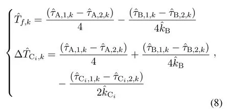
where the detailed derivation can be found in Appendix I.
Since|τA,1,k −τA,2,k| <1µs,Tf,k ≪ τA,1,k,∆TCi,k ≪τA,1,kand clock skew errors are usually no more than 20 ppm,the mean-square error (MSE)of the TDOA estimate can be approximated as
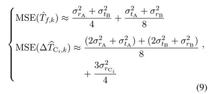
whereσ2tAandσ2tBrepresent the variance of the timestamp noise in the transmitting process of the agent and the active anchor,and similarlyσ2rAandσ2rBrepresent those in receiving process.From(9),we can conclude that the MSE of the TDOA estimates is larger than that of the TOA.Additionally,the TDOA estimate is not only affected by the noise from the TWR process,but also affected by the noise from the passive listening process.Moreover,when the TOA estimation is affected by the positive bias of the NLOS propagation,the TDOA estimation will not be significantly affected which is still approximately unbiased.The proof of this conclusion is given in Appendix II.
In the case of multiple passive anchors,the TDOA measurements from these passive anchors can be also estimated by (8).Note that the TDOA from multiple passive anchors and the TOA from the active anchor are correlated with each other.Under the same conditions as the approximate equation (9),the covariance between the TOA and TDOA estimates and the covariance between different TDOA estimates are given by

where the derivation of (9) and (10) is given in Appendix I.Therefore,the covariance between the TDOA estimates from different passive anchors is close to the MSE of the TOA estimates and is much larger than the covariance between the TDOA and TOA estimates.
Through the above analysis,the MLEs of the TDOA from passive anchors are given in the closed form.Meanwhile,the proposed method can estimate the unknown clock drift relative to the reference clock,which can minimize the error caused by the unknown clock skews.
3.2 Localization Algorithm for PAAL
The AOA of signals from the agent can be estimated from the phase observations based on the method prosurements of the system can be expressed asThe maximum likelihood optimization problem is given by

where Σkis the noise covariance matrix ofTo obtain the optimal localization estimations,the covariance matrix of the measurement noise should be known exactly.However,in real environments,the noise variance and the bias of measurement in the observation process cannot be known exactly.Therefore,we employ the adaptive UKF to ensure accurate and stable tracking of the agent,which can adaptively set different weights for LOS and NLOS measurements.
First,we briefly introduce the principle of UKF.Before calculating the state vector at thek-th measurement,the sigma pointsχk−1are calculated by sampling the state vector xk−1according to the state covariance matrix Pk−1and corresponding weights are W.In the predict step,the sigma pointsχk−1are processed by the state prediction functionf(·) and becomeχf.The mean and the variance ofχfare xk|k−1and Pk|k−1,respectively.In the update step,the sigma pointsχfare processed by the measurement functionh(·) and becomeχz.The mean and the variance ofχzare xz,kand Pz,k,respectively.Define zΛ,kas the measurement vector at thek-th measurement,and the corresponding residual vector is given by

Then the UKF gain K can be calculated according toεk.Finally,the state vector xkand covariance Pkcan be obtained by using xk|k−1,K andεk.
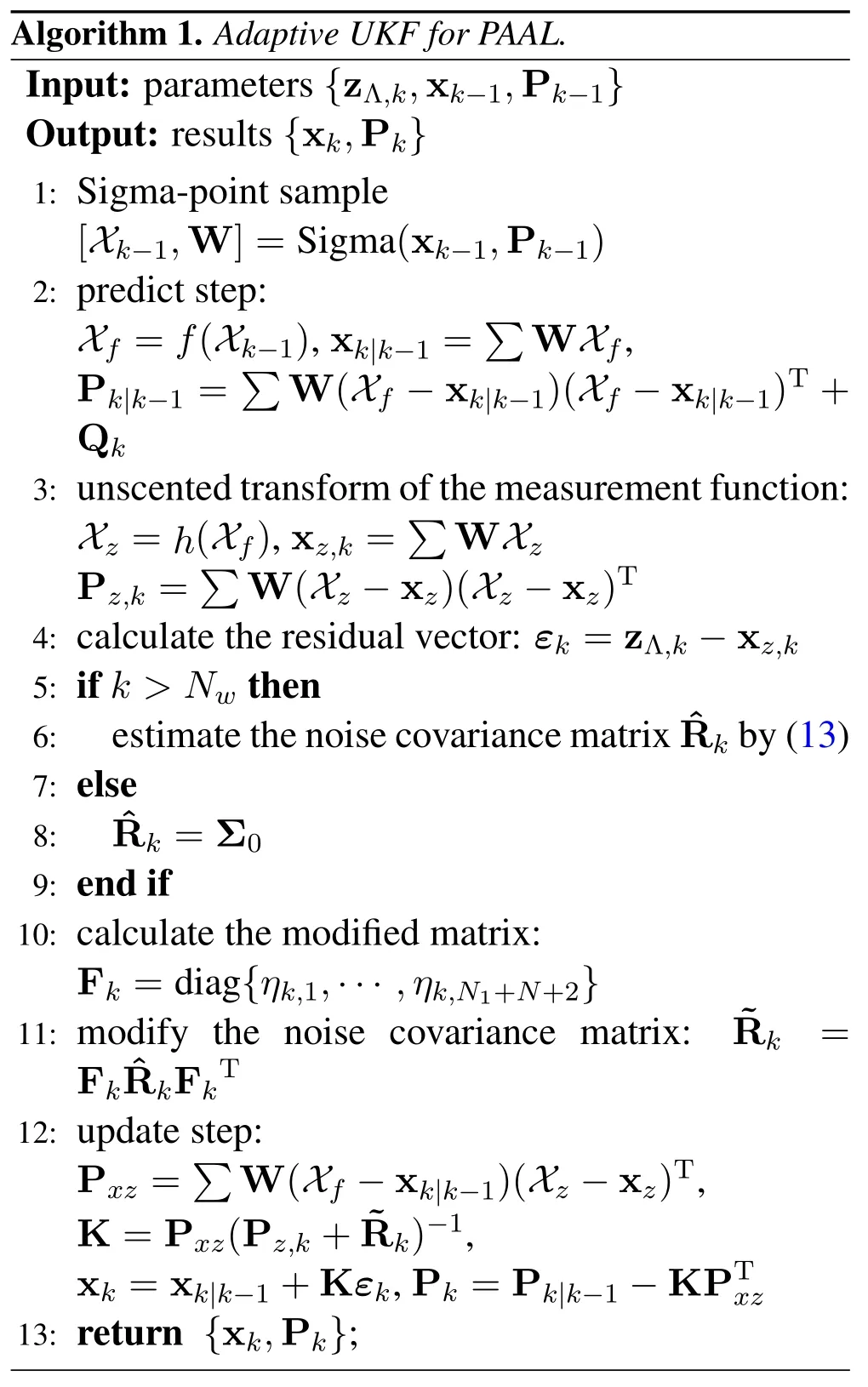
Compared with conventional UKF,the proposed adaptive UKF can use past data to estimate the noise covariance matrix.The past data can be collected by setting a sliding window with the lengthNw.The estimation of the noise covariance matrix ˆRkat thek-th measurement is given by


whereσk,iis thei-th element on the diagonal of the noise covariance matrixThen we can correct theby
?

where Fk=diag{ηk,1,···,ηk,N1+N+2}.
Note that the proposed adaptive UKF for PAAL is initialized atk=1 by the maximum likelihood localization algorithm mentioned above.The detail of our algorithm is given in Algorithm 1.
IV.PERFORMANCE LIMITS
Note that the posterior Cramer-Rao lower bound(PCRLB)can evaluate the lower bound of the estimator variance in a dynamic system,and hence in this section we derive the PCRLB to characterize the fundamental limits of the PAAL system.
Consider the unknown parameters at thek-th measurement,which can be expressed as

where ΘA,kdenotes the unknown parameters in the SAL system and ΘP,kdenotes the unknown parameters associated with the passive anchors.Specifically,ΘA,kconsists of TOA,AOA,the clock skew of the active anchor and time periods of the agent,while ΘP,kconsists of TDOA,AOA and clock skew of passive anchors.
Note that the conditional distribution of the measurement vector zkgiven ΘkfollowsN(µ(Θk),Ck).Then the FIM of the parameter Θkcan be derived as

whereµ(Θk)is the mean of zk,Ckis the covariance matrix of the measurement noise.JΘA,krepresents the FIM of ΘA,k,JΘP,krepresents the FIM of ΘP,kand JAPdenotes the joint information of ΘA,kand ΘP,k.Define the vector uk=[pTk,kB,kTC,τA,2,k,τA,1,k]Tand then the FIM of ukcan be derived as

where TA=∂ΘA,k/∂ukdenotes the transform matrix of ΘA,kand TP=∂ΘP,k/∂ukdenotes the transform matrix of ΘP,k.In(18),the first term is related to the observations of the active anchor,the second term is related to the measurements of passive anchors,and the third term is related to the joint information of ΘA,kand ΘP,k.We can conclude from (18) that adding passive anchors will increase the information about the position of the agent.
To further analyze the localization information,we use the concept of the equivalent FIM (EFIM) [13].First,we decompose the FIM Jukas

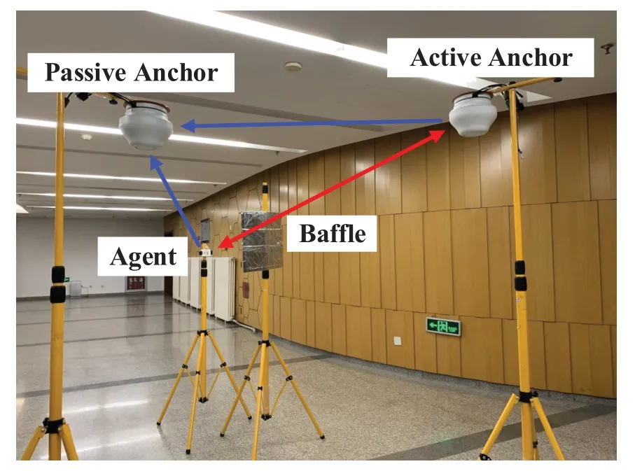
Figure3.Experimental environment:an active anchor,a passive anchor and an agent in an indoor environment.
where A∈R2×2,B∈R2×(N+3),C∈R(N+3)×(N+3),and hence the EFIM for the agent position pkcan be given by

The EFIM Fkkthat incorporates past measurements can be calculated by recursion as[40]


where‖·‖denotes the Euclidean norm.The lower bound is closely related to the number of passive anchors in the system and the relative position of the agent to the active anchor and passive anchor.
V.EXPERIMENT AND ANALYSIS
In this section,we implement the proposed localization scheme on a low-cost UWB platform and evaluate the localization accuracy in indoor environments.In addition,two kinds of passive anchors are compared in the experiments,one of which is equipped with a single antenna and the other is equipped with an antenna array.
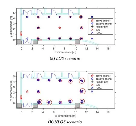
Figure4.Localization results in E1 under LOS and NLOS scenarios (a) The mean localization results and the 90%localization errors in the LOS scenario(b)The mean localization results and the 90%localization errors in the NLOS scenario.
5.1 Measurement Setup
In the proposed system,the active anchor and passive anchors are equipped with square antenna arrays and multiple DW1000 chips,and the agent is a single-chip wireless transceiver which can transmit and receive UWB signals.In particular,only the active anchor can transmit and receive UWB signals,the passive anchors only receive signals from the active anchor and the agent.
In practice,due to the error of spacing between antenna elements and the presence of coupling effects,the AOA estimates is biased.Therefore,we calibrate the spacing between antenna elements [41]and use the polynomial regression method to reduce the bias of AOA estimates.Additionally,we also calibrate the ranging estimation by calibrating the antenna delay of anchors.Then we can obtain near-unbiased ranging and AOA estimates from our devices.
We conduct two kinds of experiments:E1 is performed in an indoor corridor,and E2 is performed in an office environment,which are shown in Figure4 and Figure8,respectively.The corridor is a rectangu-
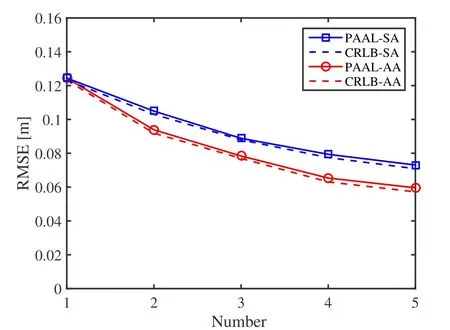
Figure5.RMSE versus the number of anchors.
lar area of 12 m×4 m,and the office is a rectangular area of 8 m×6 m.As shown in Figure3,the red arrow line represents the communication between the agent and the active anchor,and blue arrow lines represent the passive listening process.All anchors are placed at a height of 2.5 m and the agent is placed at the height of 1.5 m.Additionally,we place a baffle made of tin foil between the active anchor and the agent to artificially create NLOS propagation.In particular,the‘NLOS’ in the following experiments is only for the link between the active anchor and the agent.In the figures,‘PAAL-SA’and‘PAAL-AA’denote the PAAL where passive anchors are equipped with single antennas and antenna arrays,respectively.
5.2 Static Localization
We first evaluate the performance of the PAAL via locating the agent at fixed-points.Firstly,we evaluate the performance in the LOS scenario.As illustrated in Figure4a,the active anchor is placed at (7.00,2.20)and four passive anchors are placed at (13.00,4.20),(1.00,4.20),(1.00,0.20),(13.00,0.20),respectively.Then we select test points (black pluses) and collect measurements at each point.Then we apply PAAL to locate the agent.The localization results and errors of the SAL and the PAAL are shown in Figure4a,where the radii of circles represents the 90%localization errors.The results illustrate that PAAL performs better than the SAL in the LOS scenario.
To evaluate the performance of PAAL in the LOS scenario,we sequentially increase the number of anchors used in the algorithm.Take the test point (0,2.00) as an example.Figure5 illustrates the RMSE of the localization results and CRLB at the example point as a function of the number of anchors.For both PAAL-SA and PAAL-AA,the localization RMSEs are close to their lower bounds.The results in Figure5 also indicate that localization accuracy improves as the number of anchors in the system increases.Compared with the SAL,the RMSE can be reduced by 24.6%and 15.7%when the additional passive anchor is equipped with an antenna array or a single antenna,respectively.However,adding more anchors will not significantly improve the localization accuracy if there are sufficient anchors in the system.

Table1.Absolute error comparison between the TOA and TDOA estimates.
Next,we evaluate the performance in the NLOS scenario.As shown in Figure4b,we place an active anchor at (1.00,2.20) and a passive anchor at (13.00,2.20),while test points remain unchanged.At each point,LOS measurements and NLOS measurements are collected.In this experiment,we apply the proposed localization algorithm for PAAL to calculate the positions of these points.The localization performance of the PAAL and the SAL in the NLOS scenario are shown in Figure4b.Due to NLOS propagation,unknown biases in the TOA and AOA estimates degrade the performance of the SAL.In contrast,the proposed PAAL can use additional measurements from passive anchors to improve the positioning accuracy.
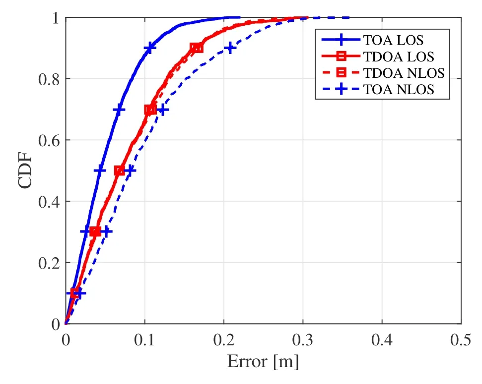
Figure6.The CDF comparison of TOA and TDOA estimation.
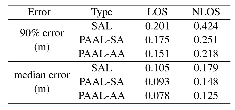
Table2.Localization error comparison between SAL,PAAL-SA,PAAL-AA.
To evaluate the performance of the proposed TDOA estimator in the NLOS scenario,we analyze the statistical characteristics of the TDOA ranging error based on the cumulative distribution function (CDF).Figure6 illustrates the ranging performance comparison between the TOA from the active anchor and the TDOA from the passive anchor,where time estimation errors have been converted into the ranging error.The ranging error comparison between TOA and TDOA is shown in Table1.In the LOS scenario,the TOA estimates can reach a 90%CDF error of 0.107m and the TDOA estimates can reach a 90% CDF error of 0.167m which is larger than that of TOA in the LOS scenario.In the NLOS scenario,the TOA estimate reaches a 90% CDF error of 0.208m which is affected by the NLOS propagation.However,the median error of the TDOA estimates in the NLOS scenario is 0.169m which is only slightly worse than that in the LOS scenario.It shows that the TDOA estimate is not significantly affected by the NLOS propagation between the active anchor and the agent.Therefore,passive anchors can provide reliable ranging information to improve the positioning accuracy when the active anchor is in the NLOS condition.
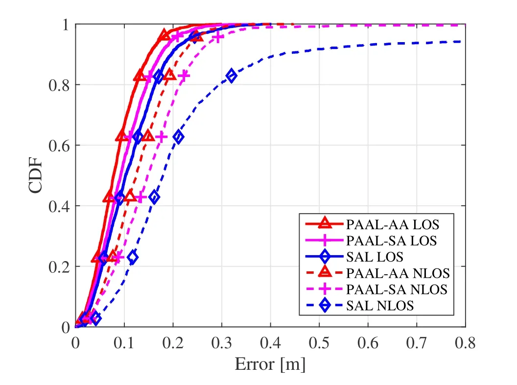
Figure7.The CDF comparison of different localization methods in LOS and NLOS scenarios.
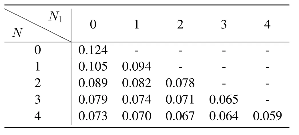
Table3.Localization RMSE (m) of the agent in the LOS scenario where N1 out of N passive anchors have antenna arrays.
We next quantify the performance of PAAL in the NLOS scenario based on the localization error CDF.Table2 shows the localization error comparison between the SAL and the proposed PAAL,and Figure7 shows the CDF curves of localization methods in LOS and NLOS scenarios.In NLOS scenarios,90% CDF errors of 0.424m,0.251m,and 0.218m are achieved by SAL,PAAL with a single-antenna passive anchor,and PAAL with an antenna-array passive anchor,respectively.Hence,the PAAL performs better than the SAL by adding a passive anchor to the SAL system in the NLOS scenario,and adding an antenna array to a passive anchor can further enhance localization performance.When there is only one antenna-array passive anchor,the 90% CDF error of the proposed PAAL in the NLOS scenario is 1.7cm larger than that of the SAL in the LOS scenario.This is because the TDOA estimates from the passive anchor is nearly as accurate as the TOA estimates from the active anchor.Moreover,Figure7 shows that the SAL can have large position errors exceeding 0.5m while the PAAL rarely have large errors exceeding 0.5m,which also demonstrates the robustness of the proposed PAAL in NLOS scenarios.
Finally,we evaluate the localization performance by different number of passive anchors with single antennas or antenna arrays.We choose the same en-vironment as that in Figure4a and keep the original test point and anchors’location unchanged.Then we change the number of passive anchors with single antennas and antenna arrays and collectM=1000 measurements at each point.Table3 and 4 show the localization RMSE of the agent in the LOS and NLOS scenarios,respectively,whereN1out ofNpassive anchors have antenna arrays.TakingN=3 in Table4 as an example,the best performance is 0.09m when all anchors equipped with antenna arrays,while the worse one 0.125m when all anchors equipped with single antennas.For fixedN,the RMSE decreases withN1and adding an antenna array to an existing passive anchor can reduce the RMSE by 12%.Compared with single-antenna passive anchors,antenna-array passive anchor can achieve better localization by obtaining extra AOA measurements,at the cost of more expensive hardware.
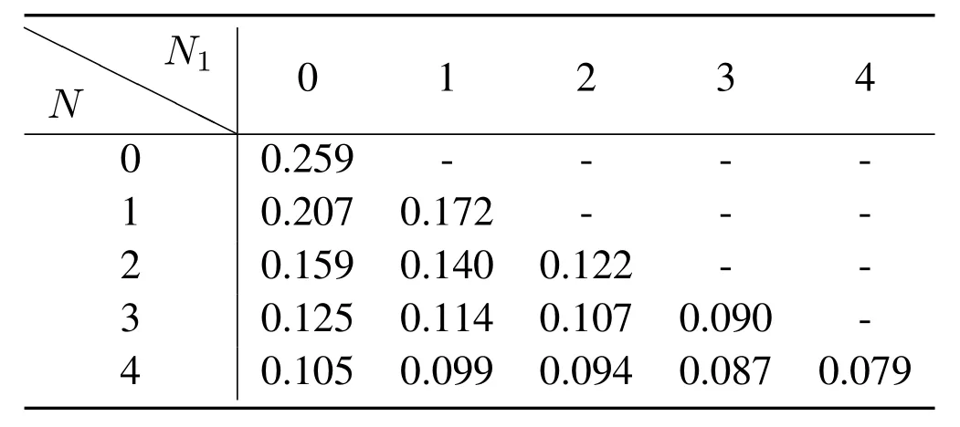
Table4.Localization RMSE(m)of the agent in the NLOS scenario where N1 out of N passive anchors have antenna arrays.
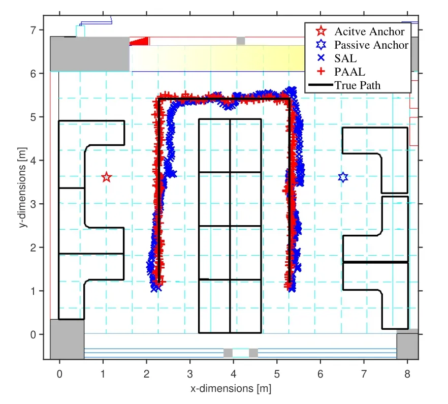
Figure8.Tracing results of the agent moving along the preset path.
5.3 Tracking Performance
In E2,we evaluate the tracking performance of PAAL in a dynamic scenario.Let the agent move along the path in an office environment.We place the active anchor at (1.07,3.64) and the passive anchor equipped with an antenna array at (6.50,3.62),which are both set at the height of 2.5 m.Besides,we hold the UWB tag at the height of 1.5 m and walk at an approximately constant speed along the path shown in Figure8.During walking,there are some moments when the propagation of signals is obstructed by the human body.
The red pentagram represents the active anchor and the blue hexagon represents the passive anchor.The black line is the true motion path.Additionally,red crosses represent the tracking results of the PAAL and blue crosses represent the tracking results of the SAL.It shows that tracking results of the PAAL method can follow the real route better than that of the SAL method,which is consistent with the localization accuracy in the fixed-point test.The experimental results verify the potential of PAAL in real indoor position applications.
VI.CONCLUSION
This paper proposed a robust UWB array loc alization scheme through passive anchor assistance,which signifciantly improves the positioning accuracy and robustness in NLOS environments.The passive anchors are employed to obtain TDOA estimates,and AOA estimates if equipped with an antenna array,via passive listening.We developed a real-time localization algorithm which can effectively fuse the measurements from LOS and NLOS propagation via proper weighing.The PAAL algorithm is implemented on a lowcost UWB platform and its performance is evaluated in indoor environments.Our results show that the PAAL can improve the localization stability in the NLOS scenarios compared with the SAL,achieving decimeterlevel localization accuracy in NLOS environments.
ACKNOWLEDGEMENT
This research was supported by the National Natural Science Foundation of China under Grant(No.61871256) and Tsinghua University Initiative Scientific Research Program.
APPENDIX I DERIVATION OF(8)-(10)
Since the derivation of TDOA estimations from different passive anchors are similar,we takeN=1 as an example.The time period measurements in zτ,kcan be expressed as
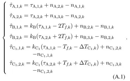
According to the system model and (A.1),we can derive the likelihood functionp(zτ,k|Θτ,k)in Section III and the derivative of ln(p(zτ,k|Θτ,k))with respect to Θτ,k,given by

Thus,the MLE of Θτ,ksatisfies the equation zτ,k −µ(Θτ,k)=0.By solving the equations,we can obtain the ML estimations of the unknown clock skews andTf,k,∆TC1,k,in the close-form(7)and(8),respectively.Based on(8),the TOA estimation error is given by
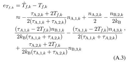
where high-order noise terms such asnA,1,knB,1,kare ignored and the noise terms in the denominator of the final fraction expression are ignored.Specifically,the second approximation holds because the time periods such asτA,1,k,τA,2,kin the UWB system are at the millisecond time scale while the noises of timestamp observation are at the nanosecond time scale.Furthermore,according to the system model,we can derive the MSE of the TOA estimation as
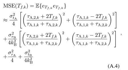
where E{·}denotes the expectation operation.Since the indoor signal propagation time is at the nanosecond time scale,|τA,1,k −τA,2,k| <1µs,|kB−1|≤20×10−6in practical UWB systems,we can obtain(9)by approximating(A.4).
Similar to the derivation of MSE(Tf,k),we first derive the TDOA estimation error as
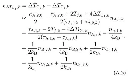
Similarly we can derive the MSE of the TDOA estimate as

Using (A.3) and (A.5),we can derive the covariance of TOA and TDOA estimates as

Similar to the derivation of (A.6),we can derive two TDOA estimation errors from two different passive anchors,which are noted ase∆TCi,kande∆TCj,k.Then we calculate the covariance of different TDOA estimates as

APPENDIX II EFFECT OF NLOS PROPAGATION
In the NLOS scenarios,the obstacles between the agent and the active anchor introduce the unknown biasbkto the distance estimates [32].Therefore,the time period measurements in the NLOS scenario can be represented withbk.Define the TOA estimation error in(A.3)asUsing the approximate operations in(A.3),the TOA estimation error in the NLOS scenario is given by

Define the TDOA estimation error in(A.6)as
Similarly,we can also derive the TDOA estimation error in the NLOS scenario as
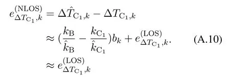
From (A.9) and (A.10),we can find that the effect of the NLOS biasbkon the TDOA estimation is negligible.
- China Communications的其它文章
- Precoder Design and Impulsive Noise Mitigation Scheme for Industrial Wireless Communications
- Shortest Link Scheduling in Wireless Networks with Oblivious Power Control
- A Proactive Selection Method for Dynamic Access Points Grouping in User-centric UDN
- Energy-Efficient Power Allocation for IoT Devices in CR-NOMA Networks
- A New Solution Based on Optimal Link-State Routing for Named Data MANET
- NOMA-Based UAV Communications for Maritime Coverage Enhancement

