
Formation process, key influencing factors, and countermeasures of high-order polygonal wear of locomotive wheels*
2021-01-13 12:56GongquanTAOXiaolongLIUZefengWENXuesongJIN
Gong-quan TAO, Xiao-long LIU, Ze-feng WEN, Xue-song JIN
Formation process, key influencing factors, and countermeasures of high-order polygonal wear of locomotive wheels*
Gong-quan TAO, Xiao-long LIU, Ze-feng WEN†‡, Xue-song JIN
†E-mail:zfwen@home.swjtu.edu.cn
Two types of high power alternating current (AC) locomotive in China are prone to serious high-order polygonal wear, which has significant negative effects on the operation of locomotives. This study investigates factors influencing polygonal wear in locomotive wheels and determines methods of minimizing operation damage. We designed experiments to analyze the process of polygonization formation of wheels to identify the key influencing factors, finding that natural vibration of wheelsets is the central inherent factor of wheel polygonization and that these vibrations can be easily stimulated by wheel or rail irregularities. We found that poor re-profiling quality is the key external factor in these irregularities. The wheelset bending resonance is activated when the remaining wheel polygonal wear has a wavelength of 200 mm in the 1/3 octave band, in turn leading to significant increases of wheel polygonal wear. In this study, we review a new wheelset design that can mitigate and/or eliminate the polygonal wheel wear due to increased stiffness in wheel bending. We evaluate the potential capacity of the newly designed wheelset and propose two proven effective measures to further improve the wheel re-profiling quality for polygonal wear.
Locomotive; Polygonal wear; Wheelset dynamic analysis; Wheel re-profiling
1 Introduction
Out-of-roundness (OOR) wheels, such as flat or polygonal-worn wheels, can induce periodic wheel– rail impacts and cause rolling stock and railway tracks to deteriorate. OOR wheels also lead to impact and/or rolling noise, and significantly increase interior noise (Zhang et al., 2014). In addition, OOR wheels can result in abnormal vibration, damage, or failure of wheel and other train components (Barke and Chiu, 2005). The impact loads induced by the polygonal wear can induce the resonance of wheelset and axle boxes and considerably increase the dynamic stress of wheelset axles (Wu et al., 2015, 2018). Although wheel re-profiling can be an effective measure to mitigate the negative effects of wheel OOR, it does not fully address all problems related to OOR wheels, especially because wheels with polygonal wear may develop rapidly after wheel re-profiling if the quality of re-profiling is poor (Tao et al., 2018b). Better understanding of underlying mechanisms of wheel polygonal wear coupled with identifying key factors influencing wear development can lead to more effective and comprehensive approaches to mitigating related problems.
In recent decades, railway researchers and engineers have made many efforts in the research of wheel polygonal wear, and have obtained abundant achievements. A lot of new viewpoints have been proposed to explain the formation cause of wheel polygonal wear by field investigation and/or numerical simulation. There are two cases reporting high- order polygonal wear of locomotive wheels. One is reported by Fröhling et al. (2019) in South Africa, and the other by the authors in China (Tao et al., 2018b). The axle torsional vibration of the wheelset is the root cause of wheel polygons with 20 harmonics in South Africa. Wheel–rail self-excited stick-slip vibration (Fröhling et al., 2019) and alternating current (AC) traction motor harmonics and interharmonics (Spangenberg, 2020) were believed to be the main excitation source of the resonance of axle torsional vibration. Two measures, i.e. active vibration suppression (Fröhling et al., 2019) and reducing variable frequency drive interharmonics (Spangenberg and Fröhling, 2020), were proposed to mitigate wheel polygonal wear. In our previous study (Tao et al., 2018a), we studied the mechanism of the polygonal wear of electric locomotive wheels, finding that the first bending resonance of wheelsets is the root cause of wheel polygons, with 18 and 19 harmonics. A great deal of additional work has been done regarding the mechanisms of wheel OOR for high-speed and metro trains that together provide robust evidence that the natural vibrations of the vehicle–track systems play a key role in the formation of wheel polygonal wear. These studies specifically investigate (1) stick-slip oscillation of wheel–rail system (Kalousek and Johnson, 1992), (2) P2 resonance (Johansson and Andersson, 2005; Li et al., 2018; Cai et al., 2019b; Tao et al., 2019), (3) frictional self-excited vibration of a wheelset–track system (Chen et al., 2011; Zhao et al., 2019; Wu et al., 2020), (4) lower bending or torsional modes of the wheelset (Jin et al., 2012; Tao et al., 2018a, 2020b; Fröhling et al., 2019; Peng et al., 2019; Spangenberg, 2020), (5) bending vibration modes of the rail or track (Johansson and Andersson, 2005; Dai et al., 2018; Cai et al., 2019a; Wu et al., 2019), (6) excited resonance of the bogie (Wu et al., 2017), and (7) vibration of other components of the bogie (Ma et al., 2016; Wei et al., 2016; Fu et al., 2019).
Recently, we conducted a detailed review of the mechanisms and effects of railway wheel polygonization (Tao et al., 2020c), in which we assessed a variety of proposed measures to combat wheel polygon wear based on associated frequency-fixing and damage (wear) mechanism of wheel polygonal wear. However, we concluded that the mechanisms underlying the formation of wheel polygonal wear for each type of vehicle or locomotive must be addressed differently because of fundamental variance among rail cars and rail locomotives, in terms of both mechanical structure and electric control systems.
Although we have explored the formation mechanism of wheel polygonal wear in one type of locomotive in China (Tao et al., 2018a), complete and generalizable studies of the formation process of wheel polygon wear have yet to be conducted. To address these research gaps, here we summarize previous studies and bring the key influencing factors into focus. Based on this clarification, we developed and proposed a new wheelset design and offer two measures to improve the quality of the wheel re-profiling.
2 Background
In early 2013, one type of Co-Co locomotive (Loco A) was found to have serious vibration problems after it had been in operation for more than a year. Wheel OOR and on-track vibration tests of the locomotive were conducted to root out the cause of serious vibration. Results indicated that the abnormal vibration was caused by wheel high-order polygonal wear, the dominant wavelength of which is 200 mm in the 1/3 octave band. Because these vibrational problems seemed to be significant at only one locomotive depot, investigators did not consider the problem to be serious enough to warrant further research. However, about one year later, several locomotive depots in mid-western China began to report similar serious problems. Except for the Loco A, Loco B (Bo-Bo) also suffered from the same problem. The Loco A and Loco B are produced by the same manufacturer.
Although the two types of locomotive have different wheelset arrangements, they do have the same structure in their wheelsets, gearboxes, and traction motors. After it became clear that the problem was not local, researchers began a series of studies to investigate the influence of wheel polygons on the vibration of locomotive components and root causes of wheel polygonal wear. These studies have focused on wheel OOR tracking test, on-track vibration testing of locomotives, experimental modal analysis of wheelsets, numerical modal analysis of other bogie components, and numerical simulation of wheel polygonal wear.
Results to date have shed new light on the core sources of wheel wear problems. Tao et al. (2018b) summarized the features of wheel OOR which indicated that the wheels of both Loco A and Loco B hadserious, high-order polygonal wear. This wear reflected the dominant harmonic orders of 18, 19, and 24, corresponding to the wavelengths of 200 mm, 200 mm, and 160 mm in the 1/3 octave band (Fig. 1). The rootcause of wheel polygonal wear with 18 and 19 harmonics is the first bending vibration of the wheelset, which was confirmed by on-track vibration testing of locomotive and experimental modal analysis of the wheelset (Tao et al., 2018a). Moreover, wheel OOR simulation results show that wheel discrete irregularities can excite the first bending vibration of the wheelset leading to wheel OOR (Tao et al., 2020a). However, the formation process, key influencing factors, and countermeasures of polygonization of locomotive wheels were not thoroughly uncovered, shortcomings this study aims to address.
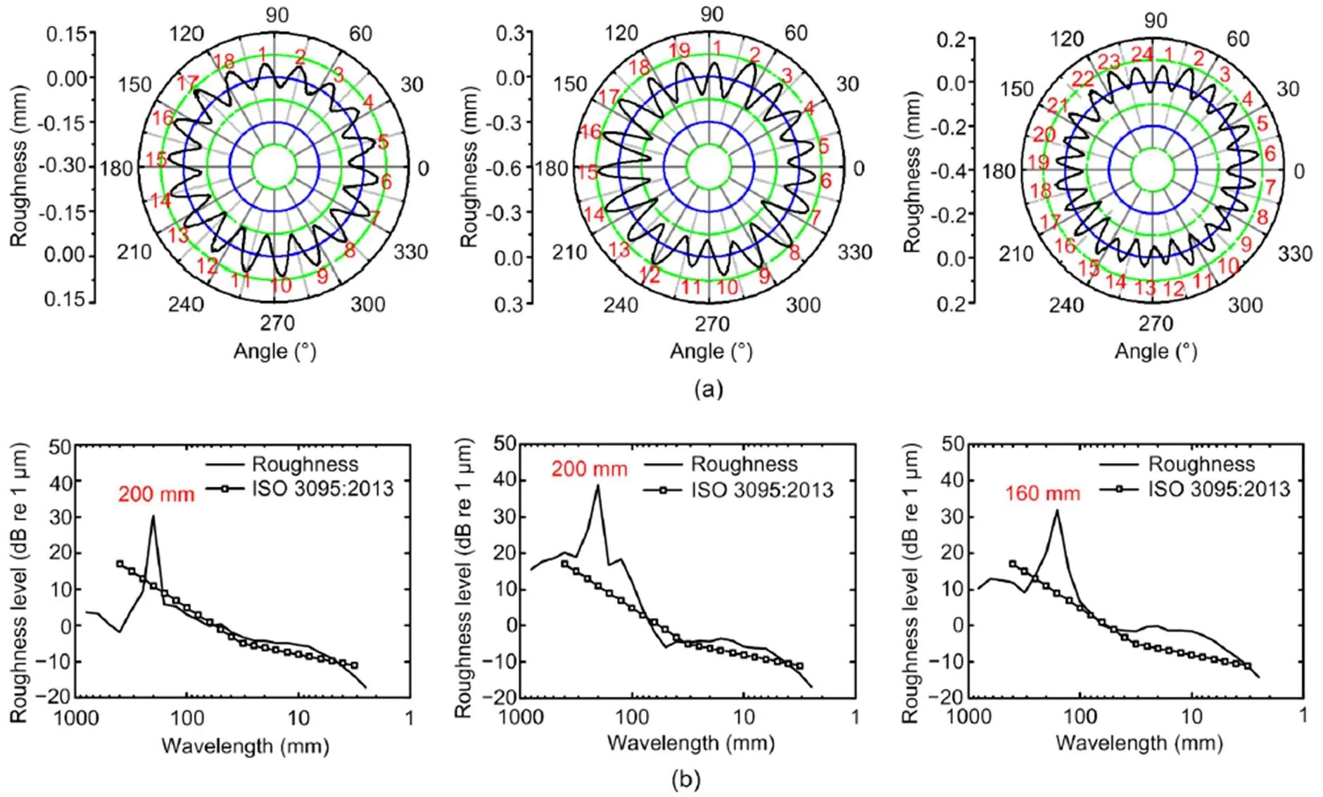
Fig. 1 Typical polygonal wear wheels with 18, 19, and 24 harmonics (from left to right) described in the polar coordinate system (a) and the 1/3 octave band spectrum of the measured irregularities (b) (ISO, 2013)
3 Formation process and key influencing factors of high-order polygonal wear
Our previous study (Tao et al., 2018a) indicated that the first bending resonance of the wheelset is easily excited during locomotive operation. The first bending resonant frequency is approximately equal to the passing frequency of a polygonal wheel with a center wavelength of 200 mm in the 1/3 octave band. The inherent factor influencing wheel polygons is the resonance of the wheelset. However, external factors warrant further study as they also play a key role. The formation and development process of wheel polygonal wear are shown in Fig. 2.
The process of wheel polygonal wear can be summarized as follows:
1. The first and second bending vibrations of the wheelset with frequencies of approximately 84 and 120 Hz, respectively, are responsible for the wheel OOR. The resonance frequency is fixed. However, the speed of the locomotive usually varies within a certain range, such as 70–78 km/h for freight traffic on the main railway lines. The lower bending resonance can be excited easily during locomotive operation. The wavelength of the wheel OOR can be expressed as=/, whereis the speed of locomotive, andis the excitation frequency, which mainly ranges from 160 to 260 mm. The lower bending resonance of the wheelset is an inherent factor of wheel polygons.
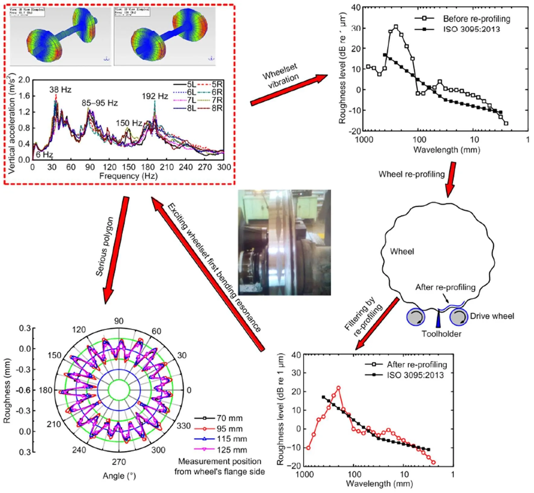
Fig. 2 Formation and development process of wheel polygonal wear (ISO, 2013)
2. The axle load of the locomotive is 25 t. Generally, the traction load of the locomotive is more than 4000 t. The wear of locomotive wheels is significantly higher than that of other non-powered vehicle wheels. Wheel OOR occurs at all wheel treads. To create the desired wheel profile, locomotive wheels are re-profiled by an underfloor wheel lathe. However, type-A underfloor wheel lathes have structural characteristics that render the lathe unable to remove irregularities of wheel OORs with a center wavelength of 200 mm in the 1/3 octave band. If the wheel exhibits an OOR with a wavelength ranging from 160 to 260 mm, irregular wear with a wavelength of approximately 200 mm will remain after re-profiling by type-A lathes.
3. Wheels with remaining OOR with a wavelength of approximately 200 mm after re-profiling will further excite the first bending resonance of the wheelset leading to additional polygonal wear that will develop rapidly with a dominant harmonic order of 18 or 19, as shown in Fig. 1.
4. Generally, brake shoes function to repair wheel OORs on locomotives that are equipped with block brakes. However, the Loco A and Loco B that suffered from a severe polygon are equipped with disk braking.
From this analysis we conclude that the lower bending resonance of wheelsets is the inherent factor of the wheel polygons. The key influencing factor promoting wheel polygonal wear is the wheel re-profiling using one type of underfloor wheel lathe although discrete wheel irregularities, such as flats, also contribute to the formation of wheel high-order polygonal wear (Tao et al., 2020a).
The locomotives that have developed serious high-order polygonal wear have been mainly in the mid-western China, where locomotive depots use type-A underfloor wheel lathes. Therefore, rail system managers needed to improve the structure of wheelsets and the quality of wheel re-profiling as concrete steps to address the costly problems associated with wheel polygonal wear.
4 Efforts to decrease high-order polygonal wear
4.1 Improving the structure of the wheelset
4.1.1 Experimental modal analysis of the original wheelset
To improve the structure of locomotive wheelsets, designers must have accurate measures of the dynamic characteristics of the original wheelsets, information that can be calculated through experimental modal analysis (EMA). Here, we performed EMA to find needed modal parameters such as eigen- frequencies, mode shapes, and damping (for details, see Tao et al. (2018a)).
Fig. 3a shows the lateral frequency response functions (FRFs) of a fixed point on the wheel rim when the rim is excited in a lateral direction along its edge. Our results reflect the wheelset lateral dynamic response when the wheel is excited laterally, such as when it is positioned to negotiate sharply curved tracks or switch crossings. Fig. 3b shows the lateral FRFs of a fixed point at the wheel rim when exciting in a radial direction along the wheel tread, as it would be when subject to vertical unevenness such as a rail weld joint, flats on rails or wheels, rail corrugation, and wheel polygons. Fig. 3c shows the tangential FRFs. The modal parameters within 400 Hz are summarized in Table 1. The mode shapes of the wheelset within 400 Hz (except for torsion mode) are shown in Fig. 4.
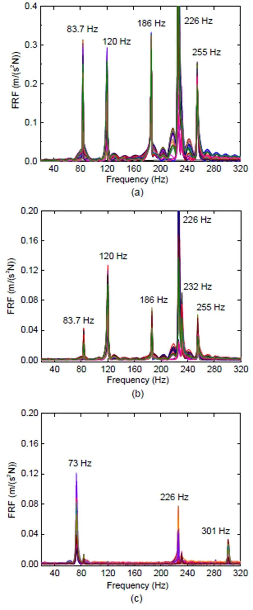
Fig. 3 Lateral dynamic response of a fixed point on wheel rim excited in a lateral direction along its edge (a) and in a radial direction along the wheel tread (b), and tangential dynamic response when excitation point is fixed whereas response points are moved (c)
The first and second bending modes of a wheelset are shown in Figs. 4a and 4b, with the corresponding eigen-frequencies of 83.7 and 120 Hz, respectively, coinciding with the passing frequencies of wheel OOR with center wavelengths of 200 and 160 mm in the 1/3 octave band, respectively. In addition to the first and second bending modes, the first torsion mode is 73 Hz, the first umbrella mode (symmetric) and the second umbrella mode (antisymmetric) occur at 188 and 255 Hz, respectively. The wheel mode shape with two nodal diameters occurs at approximately 226 Hz for the left- and right-wheel individual deformations. The gear wheel bending mode with one nodal diameter and the gear wheel torsion mode are 232 and 301 Hz, respectively, which are confirmed by numerical modal analysis (NMA) (Section 4.1.3).
The EMA shows that the wheelset axle has little deformation for the second bending mode, as shown in Fig. 4b. Therefore, even if this mode develops during locomotive operation, it is impossible to detect even with accelerometers installed on axle boxes. However, with lateral excitation the second bending mode can be excited as easily as the first bending mode, as shown in Fig. 3a, and is more easily excited than the first bending mode with the radial direction excitation, as shown in Fig. 3b.
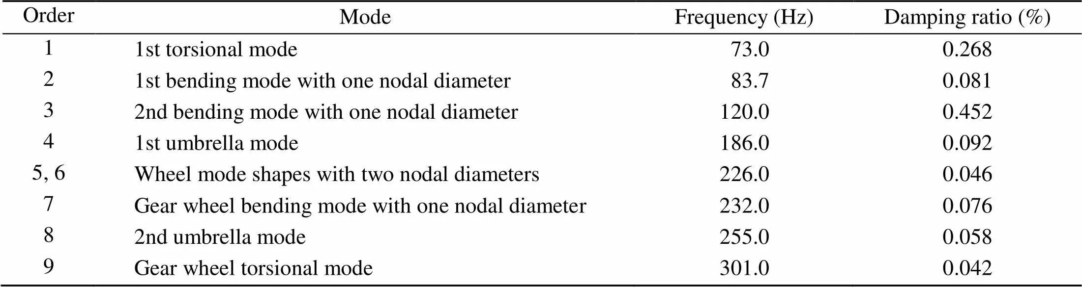
Table 1 Vibration modes of the wheelset
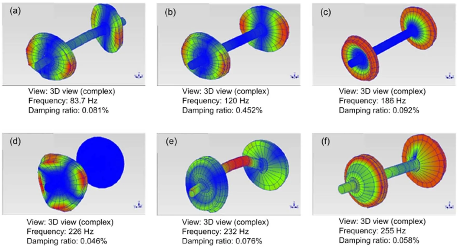
Fig. 4 Mode shapes of the wheelset within 400 Hz: (a) first bending mode of the axle with one nodal diameter, (b) second bending mode of the axle with one nodal diameter, (c) first umbrella mode, (d) one-wheel deformation with two nodal diameters, (e) gear wheel bending mode with one nodal diameter, and (f) second umbrella mode
4.1.2 Design idea of the new wheelset
Based on the analysis presented above, we found that natural vibrations of the wheelset are the root cause of the wheel OOR with center wavelengths of 200 and 160 mm in the 1/3 octave band. If this is correct, a key to mitigating or eliminating the formation of wheel polygons would be to change the characteristics of wheelset vibrations. This change could be done by either increasing or decreasing the natural frequencies based on the frequency-fixing mechanisms. To test this idea, we designed a new wheel with a different structure, as shown in Fig. 5.
We found that the wheel web of the original wheel was not sufficiently strong, as represented by the black solid line in Fig. 5, largely because the bending stiffness was low, allowing wheel bending vibrations to be easily generated. If the bending resonance of the wheelset is excited, the lateral creep between the wheel and rail increases considerably due to lateral vibration, a problem that is addressed in the redesign by increasing the lateral stiffness of the wheels. To increase lateral stiffness, our newly designed wheel adds about 35 kg to the structure where indicated by the dashed lines in Fig. 5. To keep the structure balanced, we decreased the thickness of the wheel rim as denoted by the dotted line in the figure.
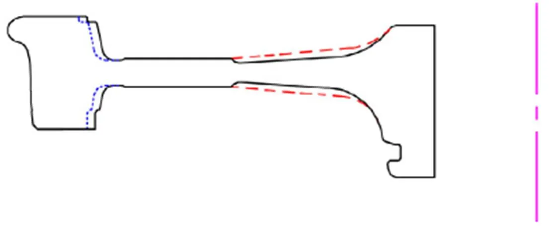
Fig. 5 Comparison of the original and the newly designed wheels
To verify that these changes would indeed moderate or eliminate the formation of OOR, we built a wheel finite element (FE) model and tested it by applying measured lateral force to the middle of the wheel rim with fixed nodes on the wheel hub. We found that this specific change of thickness significantly increased wheel bending stiffness and decreased wheel deformation by about 42%, a significant improvement over the original.
4.1.3 Numerical modal analysis
The NMA comparison of the original and new wheelset designs was done with commercial FE analysis software ANSYS. The main assumptions and simplifications in the model are as follows:
1. The wheels and the gear wheel are directly connected to the wheelset axle.
2. The relative motions between the wheels and the gear wheel and wheelset axle are ignored.
3. The brake disks are directly connected to the wheels with bolts and the relative motions between them are ignored.
4. Some holes and chamfers are ignored.
A solid hexahedral element with eight nodes was used for the modelling of the original and the newly designed wheelsets. The FE model includes 71 589 elements and 81 885 nodes. A free boundary condition was assumed, and the Lanczos solver was employed to calculate the eigenvalues and eigenvectors.
The NMA results of the original wheelset are illustrated in Fig. 6. The mode shapes coincided with those obtained by EMA. The eigen-frequencies calculated by the FE model were very close to the EMA results. Mode shapes and modal frequencies were validated by experimental data with an acceptable margin of error.
Next, the NMA of the newly designed wheelset was performed with mode shapes identical to the original. However, the eigen-frequencies were different from those of the original. Table 2 provides experimental and numerical data on the eigen-frequencies of the original and new wheelsets showing that two key frequencies were changed, particularly that of the second bending mode with one nodal diameter. The frequency of 119 Hz in the original wheelset increased to 144 Hz in the new design. The frequency of the first bending mode with one nodal diameter also increased from 82 Hz to 90 Hz in the newly designed wheelset.
4.1.4 Harmonic response analysis
We evaluated the dynamic characteristics of the original and the newly designed wheelsets using harmonic response analysis. The FE models were similar to the ones in the modal analysis, while longitudinal, lateral, and vertical spring-damper elements at each end of the wheelset were used to limit the rigid body motion of the wheelset, as shown in Fig. 7. A small stiffness of 0.5 MN/m is adopted, and there is no damping in the spring-damper elements. The flexible mode shapes and eigen-frequencies coincided with the free boundary model after adding spring-damper constraints, and the rigid body motions were kept at frequencies far below the lowest structural eigen-frequencies. The excitation point and response point were located at the middle of the wheel rim with an interval between the excitation and response points of 22.5°. The excitation and response directions were parallel to the axle, as shown in Fig. 7. A unit force (1 N) harmonic excitation was applied for the harmonic response analysis.
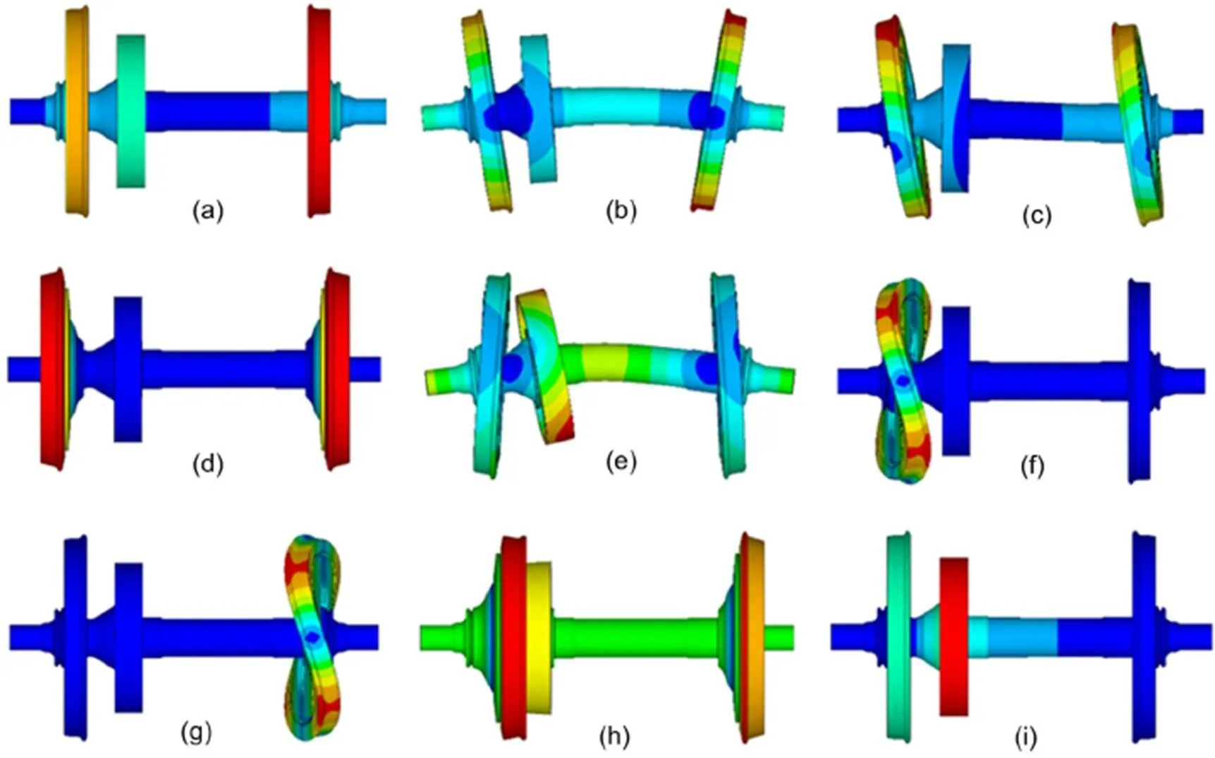
Fig. 6 NMA of the original wheelset: (a) first torsion mode (72 Hz); (b) first bending mode of the axle with one nodal diameter (82 Hz); (c) second bending mode of the axle with one nodal diameter (119 Hz); (d) first umbrella mode (180 Hz); (e) gear wheel bending mode with one nodal diameter (232 Hz); (f) left wheel deformation with two nodal diameters (239 Hz); (g) right wheel deformation with two nodal diameters (239 Hz); (h) second umbrella mode (252 Hz); (i) gear wheel torsion mode (300 Hz)
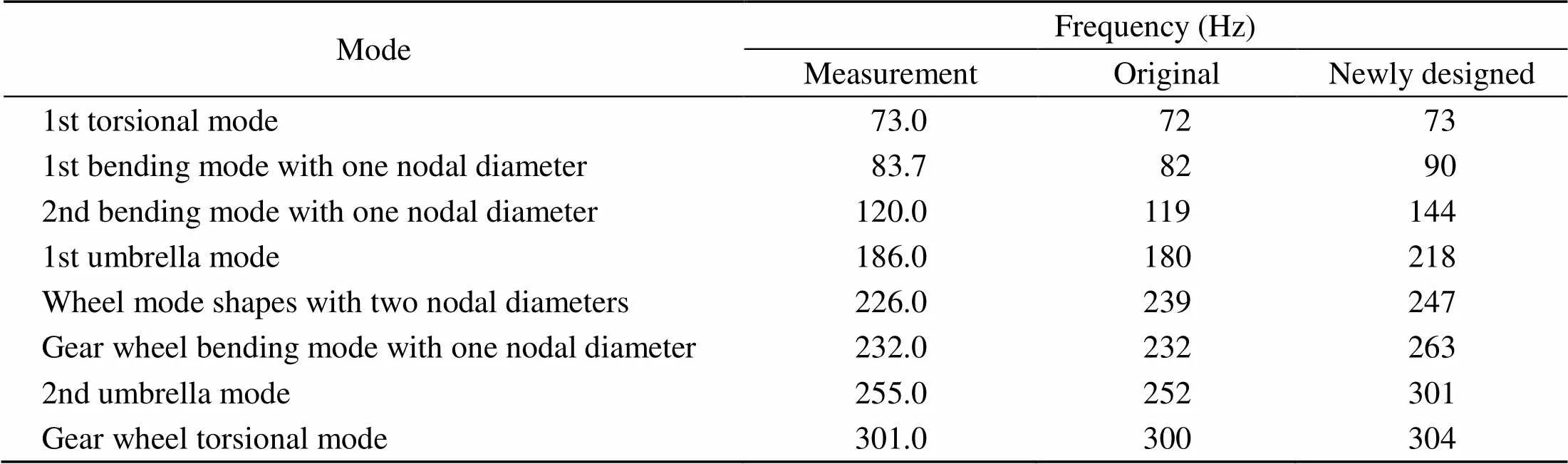
Table 2 Comparison of eigen-frequencies between the measured and numerical results
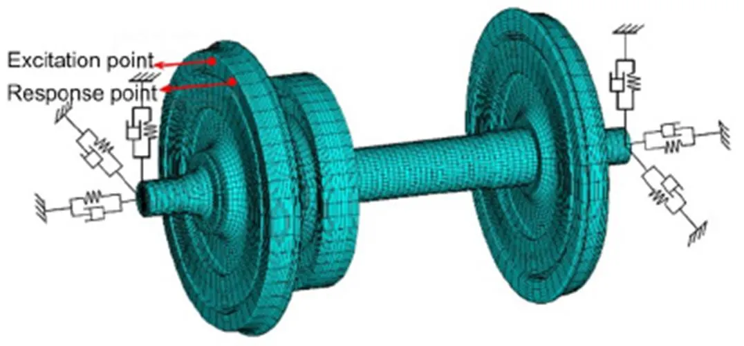
Fig. 7 Frequency response analysis model of the locomotive wheelset
Fig. 8 shows a comparison of the harmonic responses of the original and the newly designed wheelsets. After the thickness of the wheel web was increased, the eigen-frequencies were different from those of the original wheelset. The eigen-frequency increased for the same mode shape, and the peak values decreased for the two key modes. This improvement measure significantly changed the dynamic response of the wheelset. The change was moreobvious for the peak value of the second bending mode (144 Hz), which significantly decreased compared with the original one. Based on the frequency- fixing mechanism, the initiation and development of the wheel polygons could be mitigated and/or eliminated.
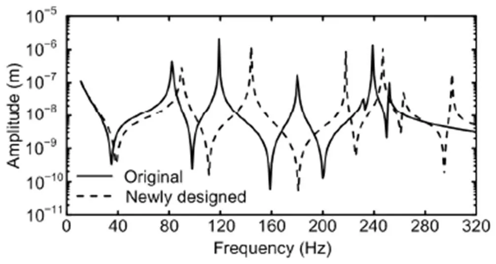
Fig. 8 Comparison of the frequency response function of the original and the newly designed wheelsets under harmonic excitation
4.1.5 Dynamics response analysis
To further explore the mechanism of the polygonal wear, we studied a specific electric locomotive that had developed serious polygonal wear focusing on the flexibility of the wheelset in a dynamic model. Using the commercial multibody software SIMPACK, we developed a rigid-flexible coupled locomotive dynamic model (Fig. 9) that included a rigid car body supported on two rigid bogie frames through secondary suspension. Four flexible wheelsets were coupled to two bogie frames through primary suspension. The modes listed in Table 2 were considered in the current model. Each wheelset was equipped with an axle-mounted motor that connected to the bogie frame through a suspender. The bogie frame and car body had six degrees of freedom, i.e. the longitudinal, lateral, and vertical displacements, and the roll, pitch, and yaw angles. Only the pitch motion was considered for the motor.
The primary suspensions, which link the axle boxes with the bogie frame, included the flexi-coil, longitudinal rod of primary suspension, a motor suspender, and a primary vertical damper. The flexi-coil was made up of two coaxial springs, which mainly provided the vertical stiffness. The longitudinal and lateral stiffnesses were mainly provided by the longitudinal rod. A nonlinear primary damper was responsible for damping of the vertical relative displacements. The secondary suspension included six coaxial springs for the longitudinal, lateral, and vertical stiffnesses, two nonlinear lateral and vertical dampers, a traction rod, and a lateral stop. The nonlinear characteristics of suspension elements were considered in this model.
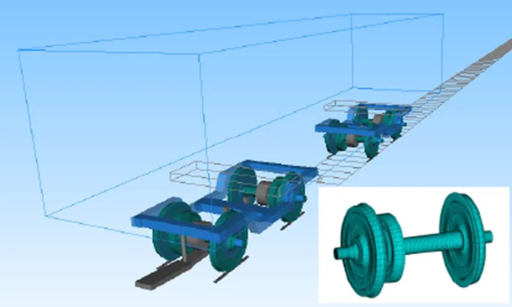
Fig. 9 Rigid–flexible coupled locomotive dynamic model
We conducted field experiments to validate our rigid–flexible coupled locomotive dynamic model. During our investigations into the mechanism of the polygonal wear, we tested the locomotive vibrations, using the axle box acceleration to validate the model. The roughness of the wheel is illustrated in Fig. 10. The wheels exhibited obvious polygonal wear, and the peak-to-peak value of the radial runout deviation is 0.297 mm. The harmonic order analysis indicated that, except for eccentricity, the dominant harmonic orders are 12, 14, and 18. The field measurement of polygonal wear was used as an input in the numerical model. The locomotive speed used was 70 km/h in both measurement and simulation.
The wavelength of each harmonic order can be expressed as a simple formula,=π/, whereis the harmonic order, andis the wheel’s diameter, which was approximately 1239 mm for the tested locomotive. The passing frequency of the wheel polygon was obtained by using=/. Therefore, the relationshipbetween the exciting frequencyeand harmonic order can be written ase≈5(Hz) for the speed of 70 km/h.
Fig. 11 shows the vertical acceleration of the axle box in the time and frequency domains. The maximum value has some deviation between the simulation and measurement, but the values are within acceptable limits because the track flexibility and short irregularities, such as rail welding irregularities, were not considered in our simulation. The maximum roughness level of the wheel is the 14th order, which corresponds to the exciting frequency of 70 Hz for 70 km/h. However, vertical acceleration of the axle box at 90 Hz is much higher than that at 70 Hz for both measurement and simulation results (Fig. 11b), because the first bending vibration of the wheelset is excited by wheel irregularities. The main vibration characteristics could be captured by the rigid–flexible locomotive dynamics model. However, the vibrations achieved by the numerical simulation between 105 and 160 Hz are higher than that of those actually measured. An obvious harmonic frequency feature is exhibited. Nevertheless, the simulation results are in good agreement with the measured results both in the time and the frequency domains, indicating that the simulation model is reliable.
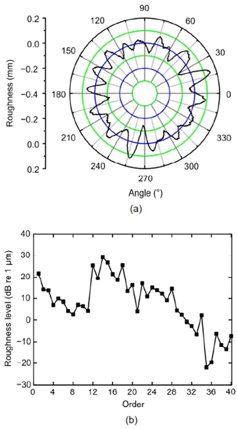
Fig. 10 Wheel polygonal wear of the experimental locomotive
(a) Described in the polar coordinate system; (b) Harmonic order levels. Reprinted from (Tao et al., 2020a), Copyright 2020, with permission from Taylor & Francis
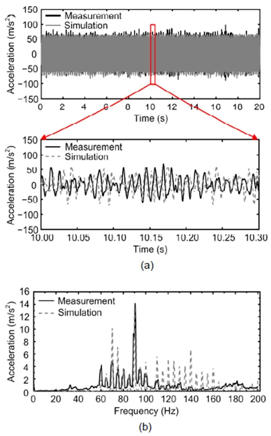
Fig. 11 Comparison of measurement and simulation results: vertical acceleration of the axle box in the time domain (a) and frequency domain (b)
The simulation results presented by Tao et al. (2020a) and Ye et al. (2020) indicated that wheel discrete irregularities can cause or exacerbate wheel polygonization. Therefore, during dynamic simulation a hypothetical discrete wheel irregularity was used to excite the wheelset vibration. The depth and wavelength of the discrete wheel irregularity are 0.2 and 340 mm, respectively. The dynamic responses of the wheel–rail contact forces of the original wheelset and the newly designed wheelset were analyzed with a simulated speed of 80 km/h and without accounting for track irregularities.
The normal forces in the time domain and frequency domain for curving negotiation are presented in Fig. 12. Fig. 12a shows that the normal forces are almost the same for the two wheelsets when the wheel rolls over the irregularity. The normal force decreases first, and then an impact vibration occurs. The maximum normal force is approximately 187 kN. Obviously, the decay rate of the newly designed wheelset is faster than that of the original. However, it did not decay to a balanced state before the next impact. The creep forces and creepages also vibrated with the same form. The frequency spectrum analysis indicates that the discrete wheel irregularity induced a significant harmonic vibration. The frequency interval was approximately 5.65 Hz, which corresponded to the rotating frequency of the wheelset at a speed of 80 km/h. The first bending vibration of the wheelset was excited by the discrete wheel irregularity. The dominant frequency for the original wheelset was approximately 90 Hz. A considerable resonance was excited. Although the first bending vibration of the newly designed wheelset was also excited, the vibration amplitude was much lower than that of the original wheelset.
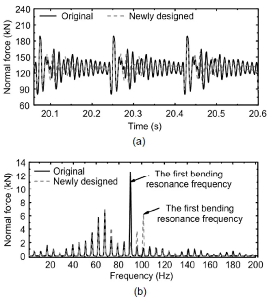
Fig. 12 Comparison of wheel–rail normal forces in the time domain (a) and frequency domain (b)
The first bending vibration of the original wheelset can be easily excited by discrete wheel irregularities. Similarly, these vibrations also can be easily excited by short irregularities such as rail weldings, insulated joints, corrugations, or shellings. After changing the wheelset structures, the dynamic response of wheel–rail contact forces is less than the original, suggesting that the new structures can effectively mitigate or eliminate wheel polygonal wear.
Our numerical simulation results similarly suggest that the newly designed wheelset can mitigate or eliminate wheel polygonal wear. Further investigations with real-sized wheelsets are needed to validate these findings.
4.2 Improving the quality of wheel re-profiling
The analysis in Section 3 demonstrates that the wheel re-profiling done with a type-A underfloor wheel lathe significantly influences the development of wheel polygonal wear. The photograph in Fig. 13 shows the underfloor wheel lathe of both types A and B, highlighting the primary difference between them as the way that the wheelset is supported during re-profiling. For type-A underfloor wheel lathe, the wheelset is primarily supported by the drive wheels. The wheelset can move vertically during re-profiling if the wheel has an obvious OOR at the contact position. However, for the type-B underfloor wheel lathe, the wheelset is fixed by a special tool that constrains its vertical movement. Tao et al. (2018b) provide measurements of wheel OOR before and after re-profiling by a type-A underfloor wheel lathe. Wheel polygonal wear with a center wavelength of 200 mm in the 1/3 octave band cannot be removed by this type of underfloor wheel lathe (Tao et al., 2018b). Fig. 14 shows some wheels re-profiled by a type-B underfloor wheel lathe. Although the wheels exhibit obvious polygonal wear with a center wavelength of 200 mm in the 1/3 octave band, the wheel OOR can be removed after re-profiling. Therefore, improving the support mechanisms for wheelset during re-profiling can significantly improve the results. Changes in lathes used at some locomotive depots confirmed that the abnormal vibration of locomotive can be effectively controlled by replacing type-A underfloor wheel lathe with type-B and that this change yields wheel OOR that remains at acceptable levels between re-profiling sessions.
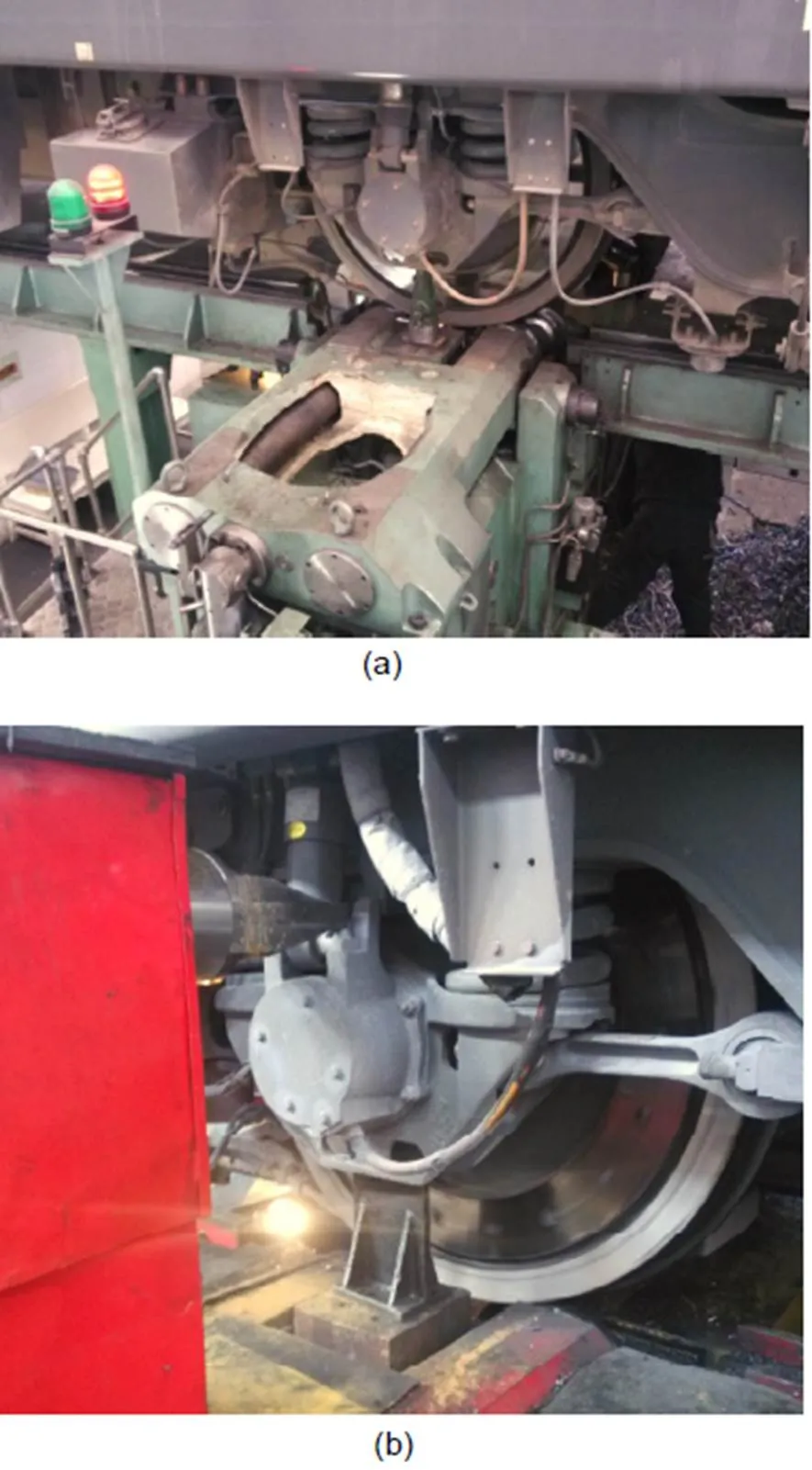
Fig. 13 Photos of the underfloor wheel lathes: (a) type-A; (b) type-B
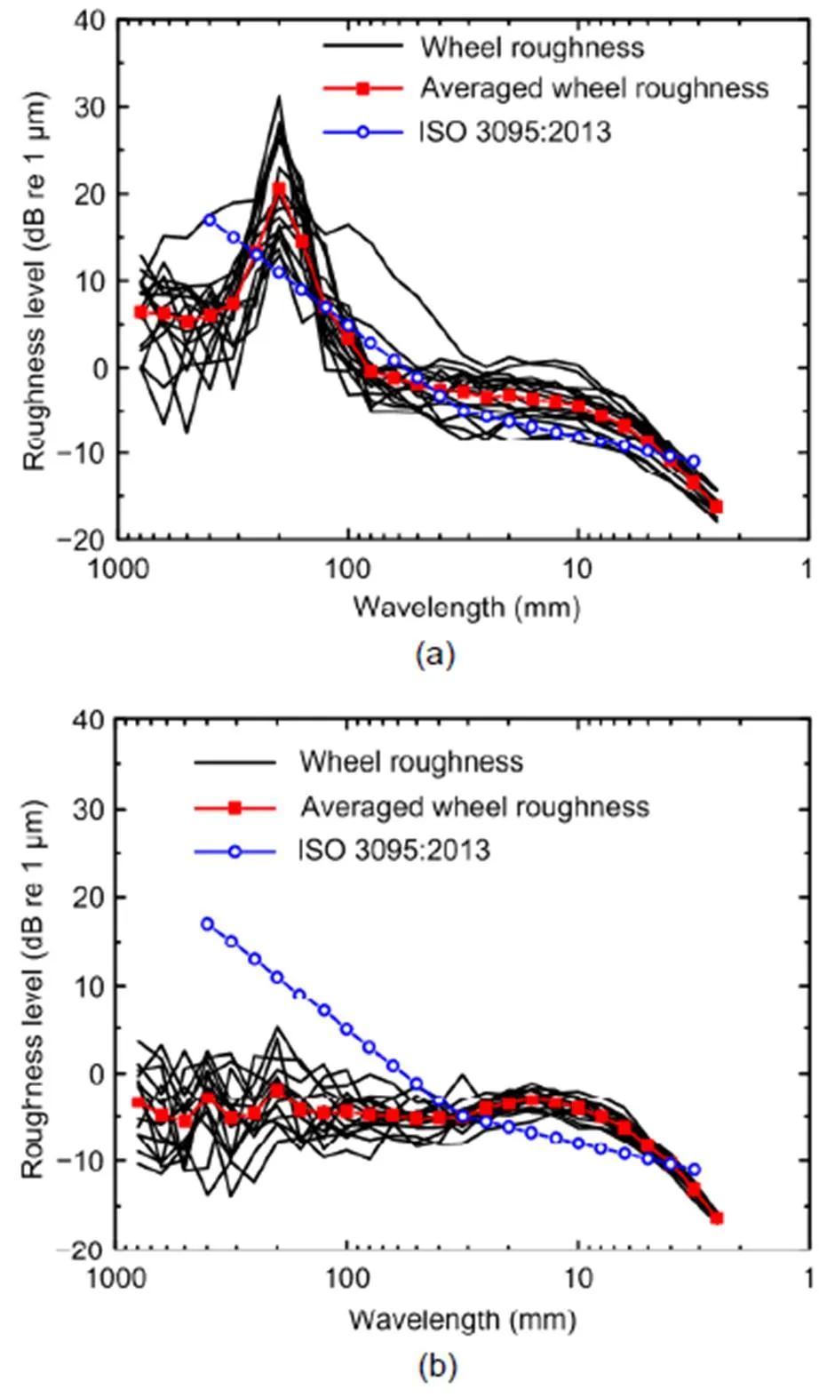
Fig. 14 Center wavelengths in 1/3 octave bands measured before (a) and after (b) wheel re-profiling by using type-B underfloor wheel lathe (ISO, 2013)
Except for the measure mentioned above, adjusting the distance of the two drive wheels of the type-A underfloor wheel lathe can also improve the quality of re-profiling. Based on the structural characteristics of type-A underfloor wheel lathe, the geometric relationship between the wheel and drive wheels of the lathe is described in Fig. 15. During re-profiling, the center of the two drive wheels is fixed; however, the center of the wheel can move. The profile of the drive wheels indwdwdwcoordinate system can be expressed as
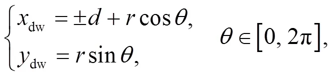
wheredwanddware the coordinates of a point on the drive wheel circumference.denotes the radius of the drive wheel (=132.5 mm), anddenotes the semi-width between the two drive wheels’ centers (=255.0 mm).is the angle between the line connecting the driving wheel center to the point on the driving wheel and the horizontal line.
The profile of a harmonic waveform polygonal wheel incoordinate system can be written as
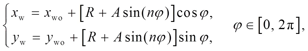
wherewandware the coordinates of a point on the wheel circumference.anddenote the amplitude and harmonic order of the polygonal wear, respectively.is the nominal wheel radius at the contact position (≈623 mm).woandwoare the coordinates of the wheel’s center (win Fig. 15).is the angle between the line connecting the wheel center to the point on the wheel and the horizontal line. Because the wheel is supported on the drive wheels, the wheel center can change during re-profiling if the wheel is polygonal at the contact position.
According to the constrained relationship of the wheel and the two drive wheels, and ignoring the elastic deformation, we can derive the following equation:
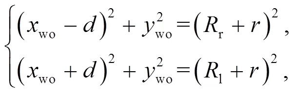
wherelandrare the actual radii of the wheel at the points contacting with the left and right drive wheels, respectively (Fig. 15).
During re-profiling, the wheelset rotates about its main axis, andlandrvary with time and can be expressed as
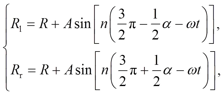
whereis the angle betweenlandr(Fig. 15),is the time, andis the rotational speed of the drive wheel.
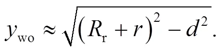
Generally, the amplitude of polygonal wear is on the order of millimeters. Therefore, the angle betweenlandrcan be considered as a constant:
From Eq. (3), we can obtain the coordinates of the wheel center:
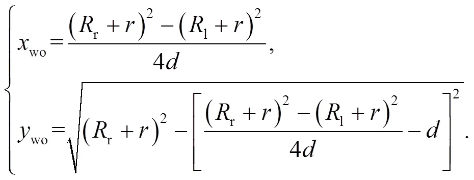
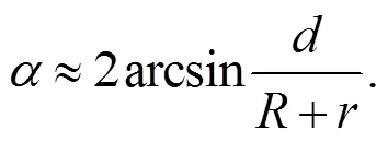
Whenwo≈0 during wheel re-profiling, the wheel polygonal wear can be removed efficiently. Detailed analysis shows that if (2−1)≈2, the equationwo≈0 can be achieved, as demonstrated in our previous study (Ren et al., 2019). If we can obtain the dominant harmonic order of the polygonal wear before re-profiling, the relationship (2−1)≈2can be satisfied through adjusting the distance between the two drive wheels of the underfloor wheel lathe.
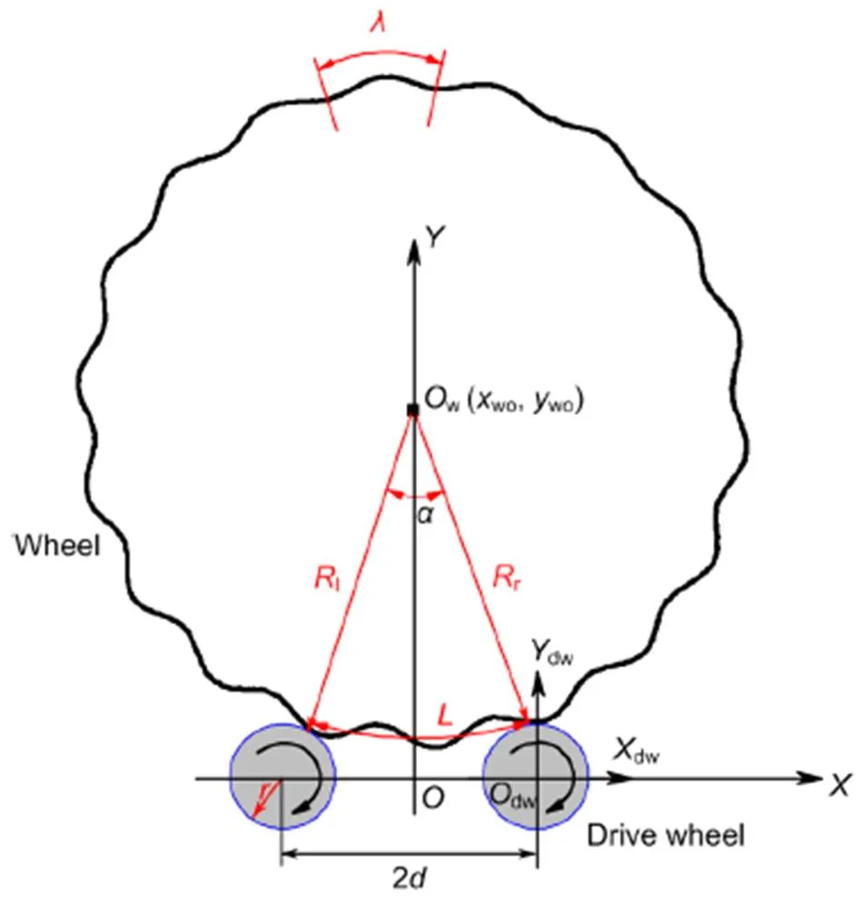
Fig. 15 Geometric relationship between the polygonal wheel and the drive wheel of the lathe
5 Conclusions
Through extensive field studies, we were able to analyze and summarize the complicated process of the formation process of polygonal wheel wear. We determined that the key influencing factor of wheel polygonization was the natural vibration of the wheelset and that poor-quality re-profiling was the key external factor. Because the bending stiffness of the original wheel web was relatively low, wheel bending vibrations could be easily excited during locomotive operation. To address this problem, we designed a new wheel web with increased wheel web thickness and validated improved operational results of the new designs. Our new wheelset had significantly different dynamic characteristics from the original, especially in terms of the eigen-frequencies related to the formation of wheel polygonization. However, these measurements should be validated with additional studies. In addition, we found that low-quality and inconsistent re-profiling of wheels plays a prominent role in the rapid development of wheel polygonization with a center wavelength of 200 mm in the 1/3 octave band. Specifically we found that one type of underfloor wheel lathe was not able to effectively remove polygonal wear, leaving behind polygonal wear with a center wavelength of 200 mm after re-profiling. The first bending vibrations of the wheelset can be excited by remaining polygonal wear, leading to rapid development of wheel polygonization. We proposed two measures for improving the wheel re-profiling quality, focusing on improving the way of supporting the wheelset during re-profiling and adjusting the distance between the two drive wheels of the underfloor wheel lathe. The first measure has already been adopted by some locomotive depots, resulting in notable reductions in the rates of recorded wheel polygonization. The second method for improving underfloor wheel lathe design may also yield similar advances in improving the quality of wheel re-profiling.
Contributors
Ze-feng WEN designed the research. Gong-quan TAO and Xiao-long LIU processed the corresponding data. Gong-quan TAO wrote the first draft of the manuscript. Ze-feng WEN and Xue-song JIN helped to organize the manuscript. Gong-quan TAO and Ze-feng WEN revised and edited the final version.
Conflict of interest
Gong-quan TAO, Xiao-long LIU, Ze-feng WEN, and Xue-song JIN declare that they have no conflict of interest.
Barke DW, Chiu WK, 2005. A review of the effects of out-of- round wheels on track and vehicle components., 219(3):151-175.https://doi.org/10.1243/095440905X8853
Cai WB, Chi MR, Wu XW, et al., 2019a. Experimental and numerical analysis of the polygonal wear of high-speed trains., 440-441:203079. https://doi.org/10.1016/j.wear.2019.203079
Cai WB, Chi MR, Tao GQ, et al., 2019b. Experimental and numerical investigation into formation of metro wheel polygonalization., 2019:1538273. https://doi.org/10.1155/2019/1538273
Chen GX, Jin XS, Wu PB, et al., 2011. Finite element study on the generation mechanism of polygonal wear of railway wheels., 33(1):14- 18 (in Chinese). https://doi.org/10.3969/j.issn.1001-8360.2011.01.003
Dai H, Li D, Wang J, et al., 2018. Study on the mechanism of high order out of round roughness of high speed railway train’s wheel. Proceedings of the 11th International Conference on Contact Mechanics and Wear of Rail/wheel System, p.189-195.
Fröhling R, Spangenberg U, Reitmann E, 2019. Root cause analysis of locomotive wheel tread polygonisation., 432-433:102911. https://doi.org/10.1016/j.wear.2019.05.026
Fu B, Bruni S, Luo SH, 2019. Study on wheel polygonization of a metro vehicle based on polygonal wear simulation., 438-439:203071. https://doi.org/10.1016/j.wear.2019.203071
ISO (International Organization for Standardization), 2013. Acoustics—Railway Applications—Measurement of Noise Emitted by Railbound Vehicles, ISO 3095:2013. ISO, Geneva, Switzerland.
Jin XS, Wu L, Fang JY, et al., 2012. An investigation into the mechanism of the polygonal wear of metro train wheels and its effect on the dynamic behaviour of a wheel/rail system., 50(12):1817-1834. https://doi.org/10.1080/00423114.2012.695022
Johansson A, Andersson C, 2005. Out-of-round railway wheels—a study of wheel polygonalization through simulation of three-dimensional wheel–rail interaction and wear., 43(8):539-559. https://doi.org/10.1080/00423110500184649
Kalousek J, Johnson KL, 1992. An investigation of short pitch wheel and rail corrugations on the Vancouver mass transit system., 206(2):127-135. https://doi.org/10.1243/PIME_PROC_1992_206_226_02
Li D, Dai H, Jia X, et al., 2018. Out-of-round of subway wheel caused by rail flexibility. Proceedings of the 11th International Conference on Contact Mechanics and Wear of Rail/wheel System, p.529-535.
Ma WH, Song RR, Luo SH, 2016. Study on the mechanism of the formation of polygon-shaped wheels on subway vehicles., 230(1): 129-137. https://doi.org/10.1177/0954409714529269
Peng B, Iwnicki S, Shackleton P, et al., 2019. The influence of wheelset flexibility on polygonal wear of locomotive wheels., 432-433:102917. https://doi.org/10.1016/j.wear.2019.05.032
Ren DX, Tao GQ, Liu H, et al., 2019. Analysis of abnormal turning repair for locomotive wheels with polygonal wear and improvement measures., 50(9):2317-2326 (in Chinese).https://doi.org/10.11817/j.issn.1672-7207.2019.09.029
Spangenberg U, 2020. Variable frequency drive harmonics and interharmonics exciting axle torsional vibration resulting in railway wheel polygonization., 58(3):404-424. https://doi.org/10.1080/00423114.2019.1581235
Spangenberg U, Fröhling RD, 2020. Solving locomotive wheel polygonisation by reducing variable frequency drive interharmonics., in press. https://doi.org/10.1177/0954409720904279
Tao GQ, Wang LF, Wen ZF, et al., 2018a. Experimental investigation into the mechanism of the polygonal wear of electric locomotive wheels., 56(6):883-899. https://doi.org/10.1080/00423114.2017.1399210
Tao GQ, Wang LF, Wen ZF, et al., 2018b. Measurement and assessment of out-of-round electric locomotive wheels., 232(1):275- 287. https://doi.org/10.1177/0954409716668210
Tao GQ, Wen ZF, Liang XR, et al., 2019. An investigation into the mechanism of the out-of-round wheels of metro train and its mitigation measures., 57(1):1-16. https://doi.org/10.1080/00423114.2018.1445269
Tao GQ, Wen ZF, Chen GS, et al., 2020a. Locomotive wheel polygonisation due to discrete irregularities: simulation and mechanism., in press. https://doi.org/10.1080/00423114.2020.1737148
Tao GQ, Xie CX, Wang HY, et al., 2020b. An investigation into the mechanism of high-order polygonal wear of metro train wheels and its mitigation measures., in press. https://doi.org/10.1080/00423114.2020.1770810
Tao GQ, Wen ZF, Jin XS, et al., 2020c. Polygonisation of railway wheels: a critical review., 28:317-345. https://doi.org/10.1007/s40534-020-00222-x
Wei L, Zong LX, Luo SH, et al., 2016. Research into the problem of wear creating a polygon-shaped wheel on metro trains., 230(1):43-55. https://doi.org/10.1177/0954409714523584
Wu BW, Qiao QF, Chen GX, et al., 2020. Effect of the unstable vibration of the disc brake system of high-speed trains on wheel polygonalization., 234(1):80-95. https://doi.org/10.1177/0954409719833787
Wu XW, Chi MR, Wu PB, 2015. Influence of polygonal wear of railway wheels on the wheel set axle stress., 53(11):1535-1554. https://doi.org/10.1080/00423114.2015.1063674
Wu XW, Rakheja S, Qu S, et al., 2018. Dynamic responses of a high-speed railway car due to wheel polygonalisation., 56(12):1817-1837. https://doi.org/10.1080/00423114.2018.1439589
Wu XW, Rakheja S, Cai WB, et al., 2019. A study of formation of high order wheel polygonalization., 424-425:1- 14. https://doi.org/10.1016/j.wear.2019.01.099
Wu Y, Du X, Zhang HJ, et al., 2017. Experimental analysis of the mechanism of high-order polygonal wear of wheels of a high-speed train., 18(8):579- 592. https://doi.org/10.1631/jzus.A1600741
Ye YG, Shi DC, Krause P, et al., 2020. Wheel flat can cause or exacerbate wheel polygonization., 58(10):1575-1604.https://doi.org/10.1080/00423114.2019.1636098
Zhang J, Han GX, Xiao XB, et al., 2014. Influence of wheel polygonal wear on interior noise of high-speed trains., 15(12):1002-1018. https://doi.org/10.1631/jzus.A1400233
Zhao XN, Chen GX, Lv JZ, et al., 2019. Study on the mechanism for the wheel polygonal wear of high-speed trains in terms of the frictional self-excited vibration theory., 426-427:1820-1827. https://doi.org/10.1016/j.wear.2019.01.020
*Project supported by the National Natural Science Foundation of China (No. 51875484), the Scientific Research Foundation of the State Key Laboratory of Traction Power of Southwest Jiaotong University (No. 2017TPL_T05), and the Opening Project of The State Key Laboratory of Heavy Duty AC Drive Electric Locomotive Systems Integration (No. 2017ZJKF01), China
© Zhejiang University Press 2021
https://doi.org/10.1631/jzus.A2000081
U270.1
Mar. 2, 2020;
June 16, 2020;
Nov. 16, 2020
 Journal of Zhejiang University-Science A(Applied Physics & Engineering)2021年1期
- Journal of Zhejiang University-Science A(Applied Physics & Engineering)的其它文章
- Dynamic track-soil interaction—calculations and measurements of slab and ballast tracks
- Vibration response analysis of floating slab track supported by nonlinear quasi-zero-stiffness vibration isolators*
- Environmental noise beside an elevated box girder bridge for urban rail transit*
- Mitigation of high-speed trains vibrations by expanded polystyrene blocks in railway embankments*