
Vibration response analysis of floating slab track supported by nonlinear quasi-zero-stiffness vibration isolators*
2021-01-13 12:51ZemingZHAOKaiWEIJuanjuanRENGaofengXUXianggangDUPingWANG
Ze-ming ZHAO, Kai WEI, Juan-juan REN, Gao-feng XU, Xiang-gang DU, Ping WANG
Vibration response analysis of floating slab track supported by nonlinear quasi-zero-stiffness vibration isolators*
Ze-ming ZHAO1,2, Kai WEI†‡1,2, Juan-juan REN†‡1,2, Gao-feng XU1,2, Xiang-gang DU3, Ping WANG1,2
MOE Key Laboratory of High-speed Railway Engineering, Southwest Jiaotong University, Chengdu 610031, China School of Civil Engineering, Southwest Jiaotong University, Chengdu 610031, China State Key Laboratory for Track Technology of High-speed Railway, Beijing 100081, China †E-mail: weimike@home.swjtu.edu.cn; renjuanjuan1983@hotmail.com
To improve the low-frequency vibration reduction effect of a steel spring floating slab track (FST), nonlinear quasi-zero-stiffness (QZS) vibration isolators composed of positive stiffness elements (PSEs) and negative stiffness elements (NSEs) were used to support the FST. First, considering the mechanical characteristics of the nonlinear QZS vibration isolators and the dynamic displacement limit (3 mm) of the FST, the feasible parameter groups were studied with the nonlinear stiffness variation range and bearing capacity as evaluation indices. A vertical vehicle‒quasi-zero-stiffness floating slab track (QZS-FST) coupled dynamic model was then established. To obtain a reasonable nonlinear stiffness within a few millimeters, the original length of the NSEs must be analyzed first, because it chiefly determines the stiffness nonlinearity level. The compression length of the NSEs at the equilibrium position must be determined to obtain the low stiffness of the floating slab without vehicle load. Meanwhile, to meet the dynamic displacement limit of the FST, the PSE stiffness must be increased to obtain a higher stiffness at the critical dynamic displacement. Various stiffness groups for the PSEs and NSEs can provide the same dynamic bearing capacity and yet have a significantly different vibration reduction effect. Excessive stiffness nonlinearity levels cannot effectively improve the vibration reduction effect at the natural frequency. Furthermore, they also significantly amplify the vibrations above the natural frequency. In this paper, the vertical vibration acceleration level (VAL) of the floating slab and the supporting force of the FST can be decreased by 6.9 dB and 55%, respectively, at the resonance frequency.
Floating slab track (FST); Quasi-zero-stiffness (QZS) vibration isolators; Vehicle‒track coupled dynamics; Low-frequency vibration reduction
1 Introduction
The rapid development and advancement of urban rail transit have played a vital role in promoting urban economic development and alleviating traffic congestion. However, the train-induced ground vibrations and noise have become significant issues which severely affect human health (Connolly et al., 2016; Kouroussis et al., 2019), historic buildings (Ma et al., 2011), and high-precision instruments (Ulgen et al., 2016).
Considered the most effective vibration isolation measure, steel spring floating slab tracks (FSTs) are used in many environmental-vibration-sensitive areas. Nevertheless, because the effective frequency range of the linear vibration isolators is often limited by the stiffness required to restrict dynamic displacements, the low-frequency vibration reduction effect is prevented from reaching the desired level, especially when the excitation frequency approaches the natural frequency (Carrella et al., 2008). Many theoretical and experimental studies have reached the consistent conclusion that medium- and high- frequency vibrations are effectively suppressed, but low-frequency vibrations are inevitably amplified around the natural frequency of the FSTs (Kuo et al., 2008; Gupta and Degrande, 2010; Zhai et al., 2011).
The available approaches to further mitigating the low-frequency vibrations of the FST are either to adopt heavier floating slabs, materials with better damping capabilities, or lower steel spring stiffnesses. Nevertheless, the difference in the basic frequency when using a heavier floating slab is not significant, because system mass is limited by construction cost and tunnel boundaries (Zhu et al., 2015). A new vibration attenuation track that incorporates an FST attached to dynamic vibration absorbers was developed by Zhu et al. (2017). Both theoretical and experimental results from that study proved that dynamic vibration absorbers could effectively attenuate low-frequency vibrations at frequencies of 9–16 Hz (Zhu et al., 2017). In another study, Wei et al. (2019) proposed connecting magnetorheological dampers to steel springs to improve the low-frequency vibration reduction of FSTs. Their simulations revealed that magnetorheological dampers with a modified bang- bang strategy can effectively improve the vibration reduction effect at the natural frequency. Because the conventional steel spring FST is a typical linear vibration isolation system, the decrease in steel spring stiffness results in a significant increase in the FST dynamic displacement and poses a threat to subway operation. As a result, few scholars have optimized the stiffness of linear vibration isolators to improve the low-frequency vibration reduction efficiency of FSTs.
With the advance of nonlinear theory, nonlinear vibration isolators have been developed in the field of vibration control engineering (Ibrahim, 2008). Nonlinear vibration isolators can be designed with high static stiffness to support large weights and low dynamic stiffness to isolate external disturbances so that the natural frequency can be reduced, which is helpful for vibration suppression (Lan et al., 2014). Generally, the nonlinear vibration isolators with high-static low-dynamic stiffnesses, also known as quasi-zero-stiffness (QZS) vibration isolators, are composed of positive stiffness elements (PSEs) and negative stiffness elements (NSEs). The positive stiffness is mostly provided by a compression spring, and the negative stiffness can be obtained by a special mechanism or structure which includes magnets (Xu et al., 2013; Zheng et al., 2018), inclined rods in series with horizontal springs (Danh and Ahn, 2014), Euler buckled beams (Liu et al., 2013; Huang et al., 2014),-layer scissor-like structures (SLSs) (Liu et al., 2015), and spring mechanisms, such as tension springs (Lu et al., 2013) and planar springs (Lan et al., 2014). Regardless of the type of negative stiffness structure, increasing the size of the negative stiffness mechanism can greatly expand the effective frequency band for vibration reduction (Yang et al., 2013). In addition, by adjusting the matching design of the positive stiffness, negative stiffness, and structural geometry, the QZS structure can be improved to form an ultra-low-frequency vibration isolator (Kovacic et al., 2008; Le and Ahn, 2011). For example, Zhang et al. (2004) presented a vibration isolator composed of an elastic element and Euler buckled beams to reduce the interference of basic vibrations on precision instruments. As expected, the natural frequency could be reduced from 10 Hz to 1 Hz by improving the negative stiffness. Furthermore, a multi-frequency and random excitation experiment on a vehicle seat with a QZS structure was developed by Le and Ahn (2013), and the results indicated that the proposed system had a wide frequency isolation range, especially since the resonance phenomenon almost did not occur. Many theoretical and experimental studies have been carried out to validate the low-frequency vibration reduction effect of QZS isolators (Shaw et al., 2013; Dong et al., 2017; Li and Xu, 2017), and QZS vibration isolators have been used in many engineering vibration control applications, such as vibration isolation of precision instruments, tracked ambulances, suspension systems of vehicles, and protection systems for water pumps. Although the advantages of the QZS vibration isolators are well recognized in the mentioned research, their application in FSTs to improve the low- frequency vibration reduction effect has not been reported. Unlike other application environments of the QZS vibration isolators, an FST has a strict dynamic displacement limit to ensure the safe operation of vehicles (in China, the maximum displacement of the floating slab should not exceed 3 mm). Therefore, how to achieve a high-static low-dynamic stiffness through parameter matching for the PSEs and NSEs, within the millimeter-level dynamic displacement, is the key issue of the application.
To overcome the limitations of linear vibration isolators and solve the bottleneck problem of traditional FSTs, the authors proposed nonlinear QZS vibration isolators composed of vertical PSEs and inclined NSEs to support the FST. The present paper is organized as follows. First, the nonlinear characteristics of different parameter groups are investigated based on the dynamic displacement limit of the FST and the vertical supporting force of the QZS vibration isolators for the FST. Then, a vertical vehicle‒ quasi-zero-stiffness floating slab track (QZS-FST) coupled dynamics model is developed by applying a mechanical model of the QZS vibration isolators. At last, based on the security and vibration reduction effect, the vibration responses of the QZS-FST with different parameter groups are obtained and compared to further optimize the parameters for the PSEs and NSEs. This theoretical study shows how the key parameters can be matched to achieve a nonlinear stiffness within millimeter-level dynamic displacements and how the stiffness nonlinearity level can be optimized to improve the vibration reduction effect of the FST.
2 Modeling of QZS vibration isolators
The proposed model is a QZS vibration isolator composed of a vertical PSE and inclined NSEs in parallel to support an FST, as shown in Fig. 1. These inclined NSEs were employed as stiffness correctors to provide a negative stiffness, achieved using special structures or materials. In this study, a linear spring mechanical model was adopted for the NSE, which allowed mechanical analysis of the QZS isolators. Traditional steel spring can be adopted as the PSE to ensure an acceptable displacement limit of the FST. First, the mechanical states (undeformed, initial installation, equilibrium, and dynamic states) of the PSE and NSEs were analyzed under different load conditions. By fully considering the displacement range to achieve a nonlinear stiffness, the matching order of the key parameters was then studied (Section 2.1). Second, the effects of parameter matching on nonlinear stiffness and supporting force were studied, and parameter groups were determined based on the supporting force obtained by the traditional steel spring FST simulation (Section 2.2).
2.1 System description
In Fig. 1a, all the stiffness elements are undeformed andhandare the stiffness and original length of the inclined springs, respectively.vis the stiffness of the vertical springs, andis the floating slab mass. Fig. 1b shows the QZS vibration isolation system in the initial installation state without any load. The inclined springs were compressed to length0, and the assembly angle between the horizon line and each inclined spring is denoted by. With the FST under a static load, the QZS vibration isolators were compressed downward so that these inclined springs were compressed to the maximum and horizontal, while the FST was supported only by the positive spring, as shown in Fig. 1c. Here, the length of inclined spring is denoted as, and the variabledefines the dynamic displacement of the FST in the downward positive direction.When the vehicle loadacts, the floating slab moves downward, as shown in Fig. 1d.
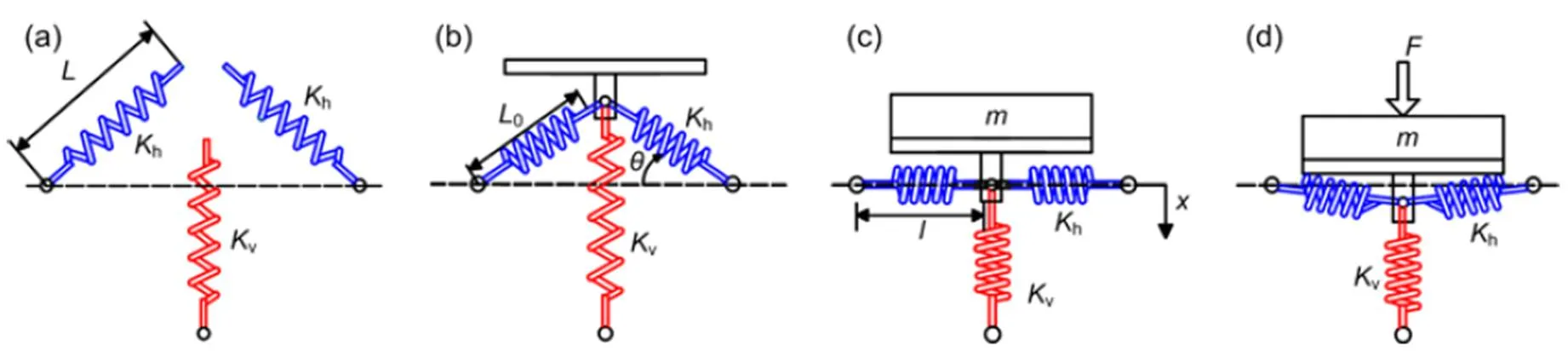
Fig. 1 QZS isolation system model diagram: (a) undeformed state; (b) initial installation state; (c) equilibrium state; (d) dynamic state
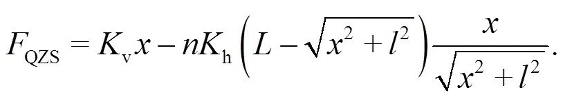
Taking the equilibrium position as the coordinate origin, the mechanical equation of the supporting forceQZScan be written as follows:
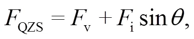
wherevandiare the compressive forces of the vertical spring and inclined springs, respectively. According to the geometric structure of the QZS vibration isolation system,vandiat an arbitrary position can be expressed as
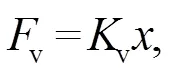
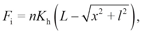
whereis the total number of NSEs. By substituting Eqs. (2) and (3) into Eq. (1), the vertical supporting force can be expressed as
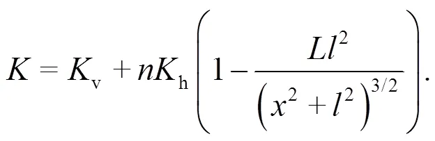
By differentiating Eq. (4) with respect to the displacement, the nonlinear stiffness of the QZS vibration isolators can be expressed as
For clarity, the following dimensionless parameters are defined:
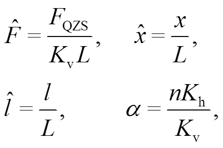
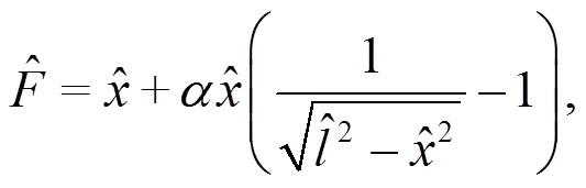
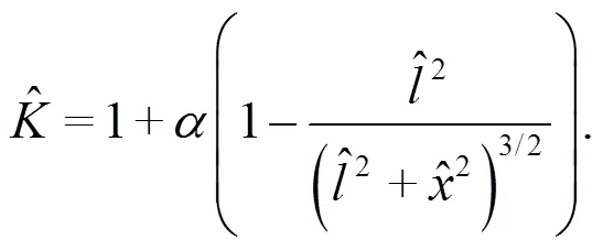
Eqs. (4) and (5) can be converted into dimensionless forms as follows:

2.2 Nonlinear stiffness analysis
The nonlinear stiffness characteristics of the QZS vibration isolators not only determine the vibration reduction effect of the FST, but also affect the dynamic displacements of the FST. Based on the parameter matching method in Section 2.1, the nonlinear stiffnesses and supporting forces of the QZS isolators with different parameter matchings were analyzed within a displacement of 3 mm. With reference to the supporting force of the steel spring FST under the same operating conditions, several parameter groups for QZS vibration isolators were preliminarily determined.
Generally, the supporting force of the steel spring isolators ranged from 20 kN to 35 kN (Wei et al., 2019; Yang et al., 2020), which was closely related to factors such as size of the floating slab and type of subway vehicle. For the basic case of a steel spring FST adopted in the subsequent calculation cases (case 1 in Table 4), the supporting force of the FST was about 28 kN when the dynamic displacement met the requirement. This value of the supporting force was used to evaluate whether the QZS vibration isolators had sufficient bearing capacities to guarantee the safe dynamic displacement of the FST.
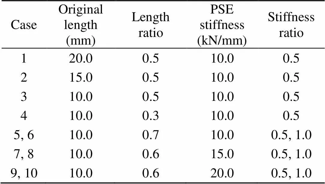
Table 1 Ten calculation cases of parameter matching
2.2.1 Original lengths of NSEs
The nonlinear stiffness and supporting forces in cases 1–3 are shown in Fig. 2. When the FST was in the state of static equilibrium under no vehicle load, the supporting stiffnesses of QZS vibration isolators with different original lengthswere 5 kN/mm. Compared to traditional linear steel spring isolators, the QZS vibration isolators provided a lower support stiffness at the FST equilibrium position; this is a feature of QZS vibration isolators also known as low-dynamic stiffness. Although the QZS vibration isolators with different original lengthsprovided the same low stiffness at the static equilibrium position of the FST, the stiffness nonlinearity level of the different isolators varied significantly under vehicle loading, especially the stiffness at the FST dynamic displacement limit. Ideally, the QZS vibration isolators should achieve a high stiffness near the FST dynamic displacement limit to ensure that the isolators have a sufficient dynamic bearing capacity to support the floating slab under a vehicle load. As shown in Fig. 2, when the dynamic displacementwas 3 mm, the support stiffnesses of the QZS isolators in cases 1, 2, and 3 were approximately 8.7 kN/mm, 7.0 kN/mm, and 6.2 kN/mm, respectively. The dynamic stiffness at the critical displacement limit gradually decreased with the increase in original length, which also revealed that the dynamic bearing capacity of the QZS vibration isolator with a greater original length was weaker within the dynamic displacement of 3 mm. As a result, the dynamic bearing capacities of the QZS vibration isolators in cases 1, 2, and 3 were 19.3 kN, 17.1 kN, and 16.3 kN, respectively. The results indicated that the shorter the original length, the stronger the stiffness nonlinearity level and the higher the dynamic bearing capacity. It is worth mentioning that the stiffnesses of the QZS vibration isolators with different original lengthsat the static equilibrium position were the same, while the stiffnesses at the critical displacement were significantly different. Taking into account the installation space of the NSEs under the floating slab, the recommended original length of NSEs is 10 mm. The bearing capacity of the QZS vibration isolators can then be improved by adjusting other parameters.
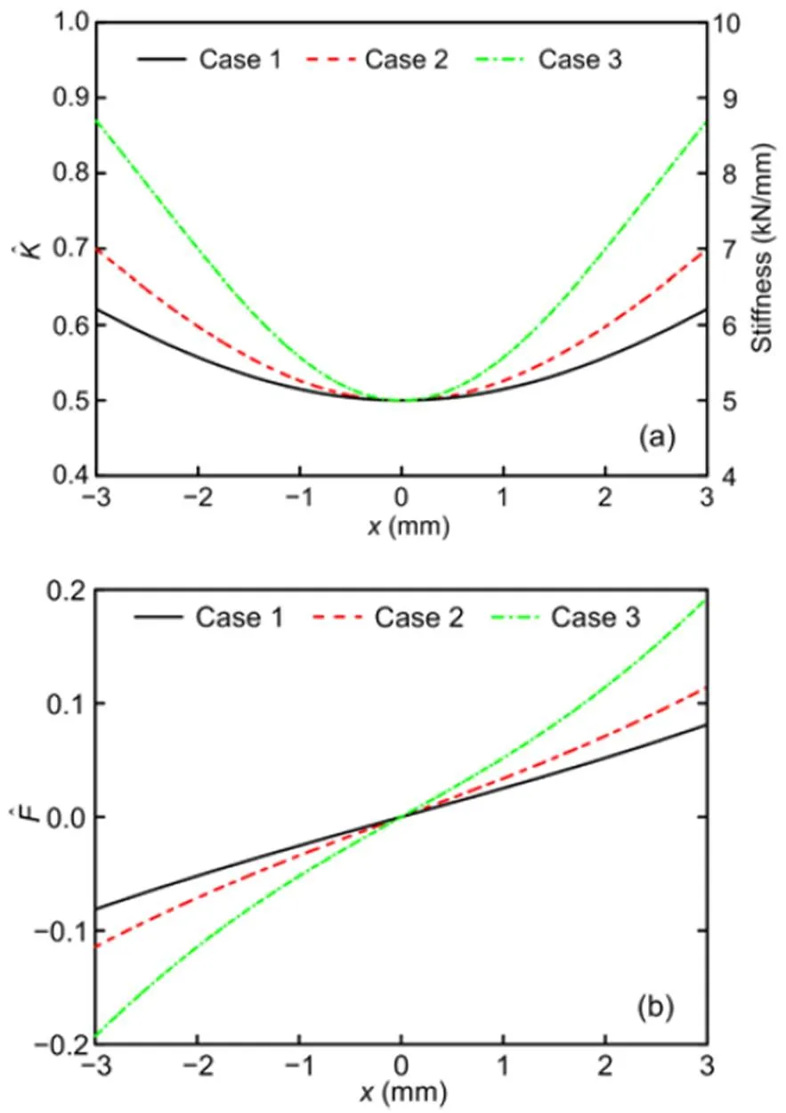
Fig. 2 Nonlinear stiffness characteristics (a) and supporting forces (b) in cases 1–3
2.2.2 Compression length of NSE at static equilibrium position
The compression length of the NSE at the equilibrium position (length ratio of NSE) is also of critical importance to the nonlinear stiffness. Fig. 3 shows the nonlinear stiffnesses and supporting forces of QZS vibration isolators at different length ratios.
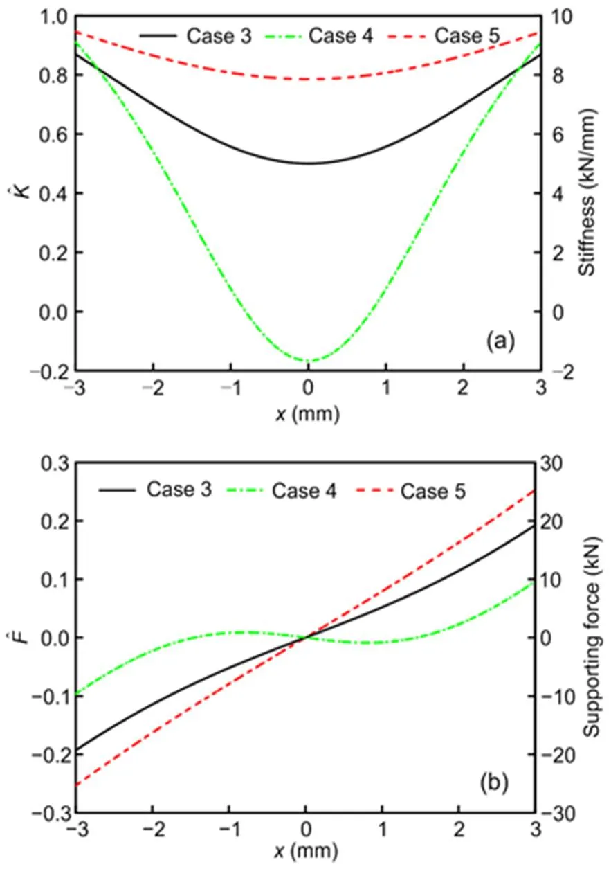
Fig. 3 Nonlinear stiffness characteristics (a) and supporting forces (b) in cases 3–5
2.2.3 Stiffness matching of PSE and NSEs
According to Eq. (4), different PSEs with the same stiffness ratio have the same dimensionless stiffness and dimensionless supporting force, so only the actual stiffness and supporting force are shown in Fig. 4.
The stiffness ranges within a displacement of 3 mm in cases 5 and 6 were 6.7–9.0 kN/mm and 3.3–8.0 kN/mm, respectively, and the corresponding bearing capacities were 22.6 kN and 15.3 kN. If the PSE used a 10.0 kN/mm steel spring, the dynamic bearing capacity of the QZS vibration isolators was insufficient, even though relatively low-stiffness NSEs were connected in parallel. The stiffness ranges within a displacement of 3 mm in cases 7 and 8 were 10.0–13.6 kN/mm and 5.0–12.1 kN/mm, respectively, and the corresponding bearing capacities were 34.0 kN and 23.0 kN. The stiffness ranges within a displacement of 3 mm in cases 9 and 10 were 13.3–18.1 kN/mm and 4.0–15.4 kN/mm, respectively, and the corresponding bearing capacities were 45.0 kN and 30.5 kN. Increasing the stiffness of the PSE can improve the bearing capacity of the QZS vibration isolators. With reference to the supporting force of the steel spring FST in this study, some stiffness groups were calculated to meet the requirement of the safe dynamic displacement. When the PSE stiffness was 15.0 kN/mm (20.0 kN/mm) and the stiffness ratio was 0.8 (1.1), the nonlinear stiffness ranged from 6.3 kN/mm (4.0 kN/mm) to 12.5 kN/mm (15.4 kN/mm) and the bearing capacity of the QZS isolators was 27.4 kN (27.6 kN). It is worth noting that there were various stiffness groups for the PSE/NSEs that could achieve the same bearing capacity, yet their nonlinear stiffness ranges varied widely. Next, the effect of different stiffness nonlinearity levels on the vibration reduction effect must be further investigated with the vehicle‒QZS-FST coupled system.
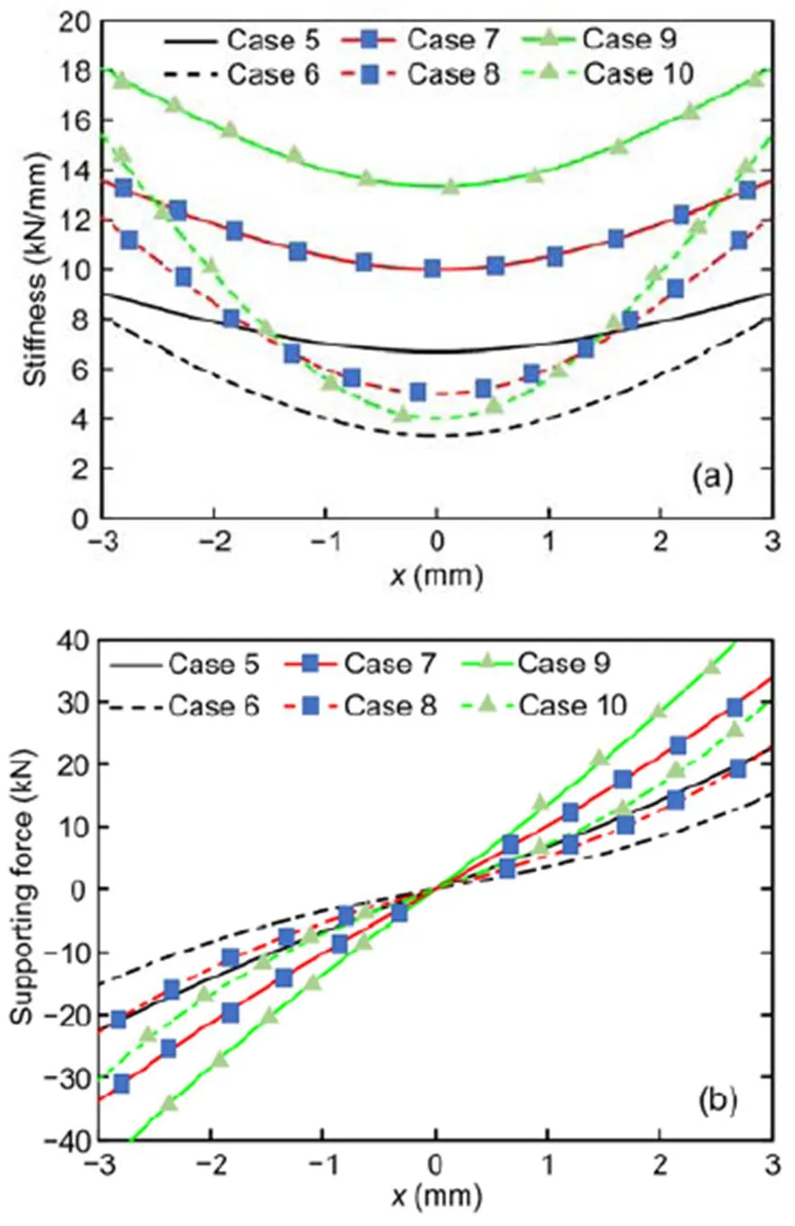
Fig. 4 Nonlinear stiffness characteristics (a) and supporting forces (b) in cases 5–10
3 Vertical vehicle‒QZS-FST coupled dynamic model
To further explore the vibration characteristics of the QZS-FST, the authors established a vertical coupled system involving railway vehicles, FST, and QZS vibration isolators, as shown in Fig. 5. In this vehicle‒track coupled system, the conventional Hertz nonlinear elastic contact theory was used to calculate the wheel‒rail relationship.
3.1 Vertical vehicle dynamic model
The numerical simulation considered a “type A” subway vehicle used in China, including one vehicle body, two bogies, and four wheelsets. The differential equations of the vehicle system can be found in (Zhai and Sun, 1994). The parameters of the “type A” vehicle are shown in Table 2.
3.2 Vertical vehicle‒QZS-FST dynamic model
The vertical QZS-FST dynamic model consists of a rail, fasteners, slabs, and QZS vibration isolators. The rail is modelled by an Euler beam, and each floating slab is modelled by a free beam supported by the QZS vibration isolators.
3.2.1 Differential equations of rail motion
According to Euler beam theory, the deformation of the rail supported by the discrete fasteners is shown by the following equation:
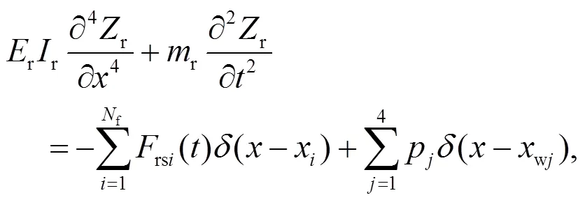
wherer,r, andrare the mass, elastic modulus, and rotational inertia of the rail, respectively;ris the vertical displacement of the rail;xandwjare the positions of theth fastener and theth wheelset, respectively;is the time;fis the total number of fastenings;() is the Dirac delta function;rsiis the vertical force applied to the rail by theth fastener, as shown in Eq. (10);pis the vertical force applied to the rail by theth wheel.
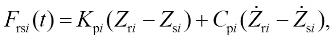
whereriandsiare the vertical displacements at theth fastener position of the rail and slab, respectively;piandpiare the stiffness and damping of theth fastener, respectively.
The partial differential equations of the rail can be made equivalent to time-dependent differential equations using Ritz’s method and normalized shape functions of Euler beams, as follows:
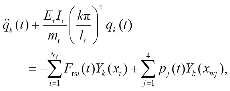
whereq() is theth generalized coordinate of the rail vertical deflection,ris the effective length of the rail, andY() is theth shape function, defined as
3.2.2 Differential equations for slab motion
Based on a model of an Euler beam with free ends, the differential equations of the floating slab supported by the QZS vibration isolators can be written as follows:
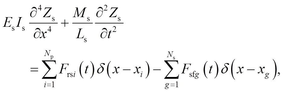
wheres,s,s, andsare the mass, elastic modulus, length, and rotational inertia of the slab, respectively;pandsare the total numbers of fasteners and isolators on each slab, respectively;sfgis the vertical force applied to the floating slab by theth QZS vibration isolator, defined as
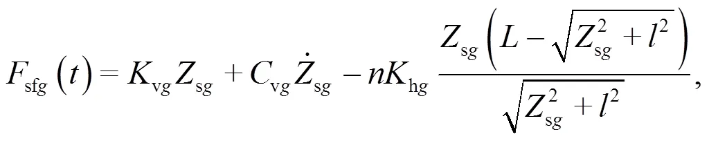
wherevgandvgare the vertical stiffness and damping of theth PSE, respectively;hgis the stiffness of theth inclined NSE;sgis the vertical displacement of the slab at theth isolator.
The partial differential equations of the floating slabs can be made equivalent to time-dependent differential equations by using Ritz’s method and normalized shape functions of the free beam, as follows:
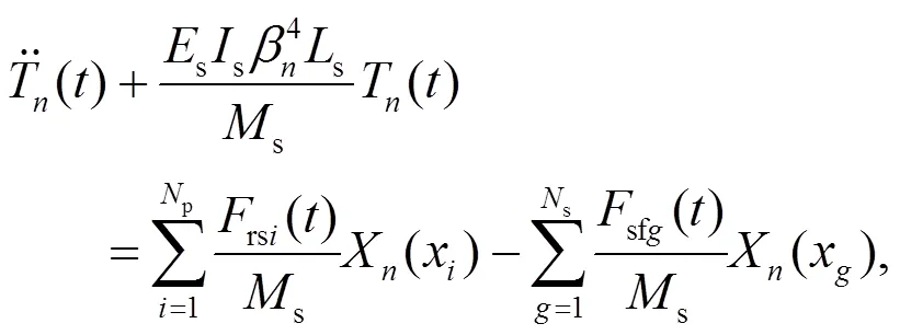
whereT() is theth generalized mode coordinate of the floating slab,Xis theth modal function, defined as
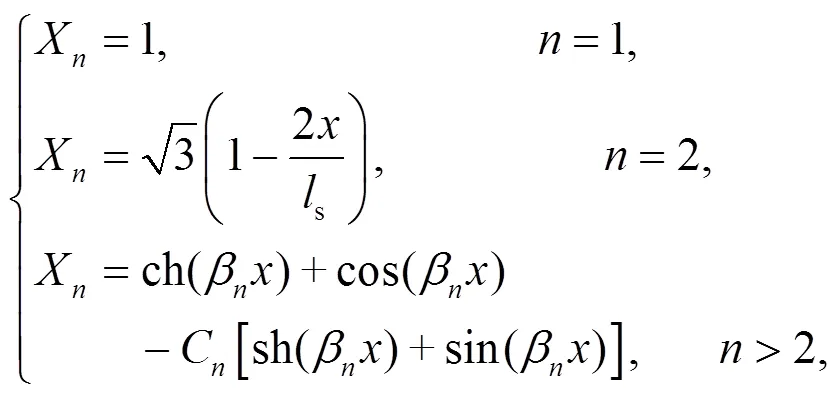
andCandβare constants of the free beam function.
Table 3 shows the parameters used in the QZS-FST numerical simulations.
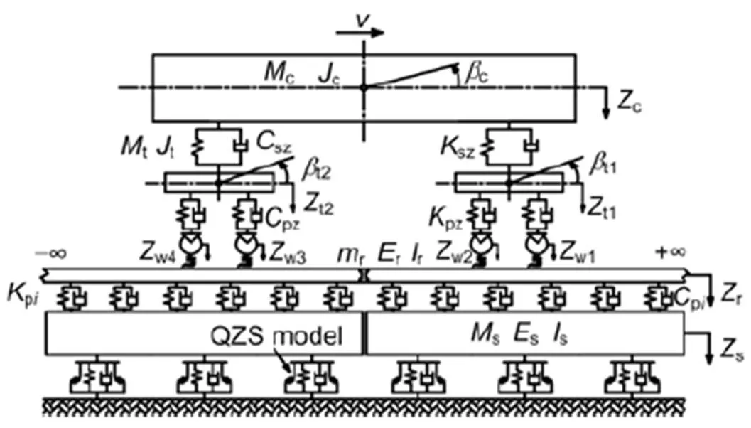
Fig. 5 Vertical vehicle‒QZS-FST coupled dynamic model
is the vehicle operating speed;c,t, andware the up-and-down movements of the vehicle body, bogie, and wheelset, respectively.candtare the nodding movements of the vehicle body and bogie, respectively
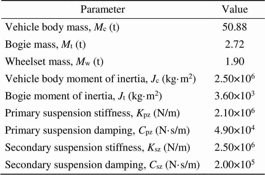
Table 2 Dynamic parameters of “type A” subway vehicle
4 Vibration response analysis of QZS-FST
To further investigate the influence of parameter matching on the safety and vibration reduction effect of the QZS-FST and reasonably optimize the stiffness nonlinearity level of the QZS vibration isolators, the authors designed a series of calculation cases based on linear isolation theory and nonlinear isolation theory (Table 4).
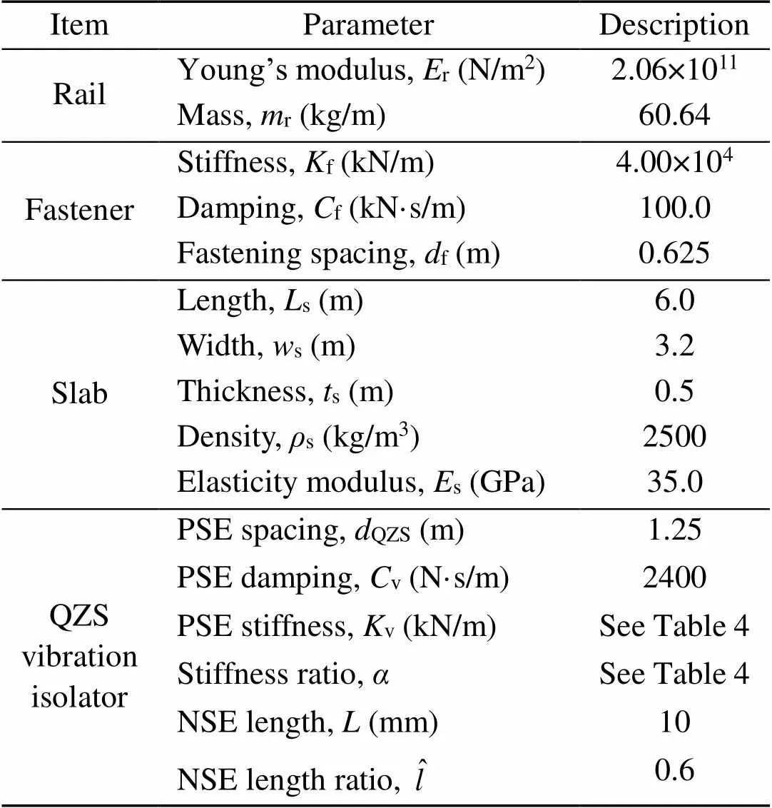
Table 3 Dynamic parameters of the QZS-FST
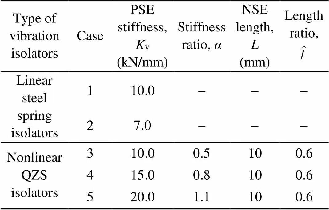
Table 4 Five calculation cases of QZS vibration isolators
The basic case is case 1, in which the steel spring isolator had a traditional stiffness of 10 kN/mm. Case 2 involved a steel spring isolator with stiffness reduction. Cases 3–5 had three QZS vibration isolators based on different stiffness groups. Cases 1‒3 contrasted the effects of the traditional steel spring vibration isolators with reduced stiffness and QZS vibration isolators on the dynamic response of the vehicle–FST. Cases 1, 3, and 4 in Table 4 were used to examine whether the dynamic displacement of the QZS-FST met the requirements after increasing the stiffness of the PSE. Cases 1, 4, and 5 (Table 4) were designed to illustrate the influence of the same bearing capacity and different stiffness nonlinearity levels on the vibration reduction effect. The stiffness–displacement curves for cases 1–5 are shown in Fig. 6. The nonlinear stiffness of the QZS isolator causes the natural frequency of the floating slab to range due to the axle load of the train rather than remaining constant. The QZS-FST had the same minimum value of the natural frequency under different axle loads, and the maximum value of the natural frequency depended on the maximum displacement (i.e. the maximum stiffness of the QZS vibration isolator) of the floating plate track under different axle loads. Thus, the natural frequencies (frequency range) of the floating slab within the dynamic displacement of 3 mm in cases 1–5 were 10.0 Hz, 8.4 Hz, 8.2–9.5 Hz, 8.0–11.3 Hz, and 6.4–12.5 Hz, respectively.
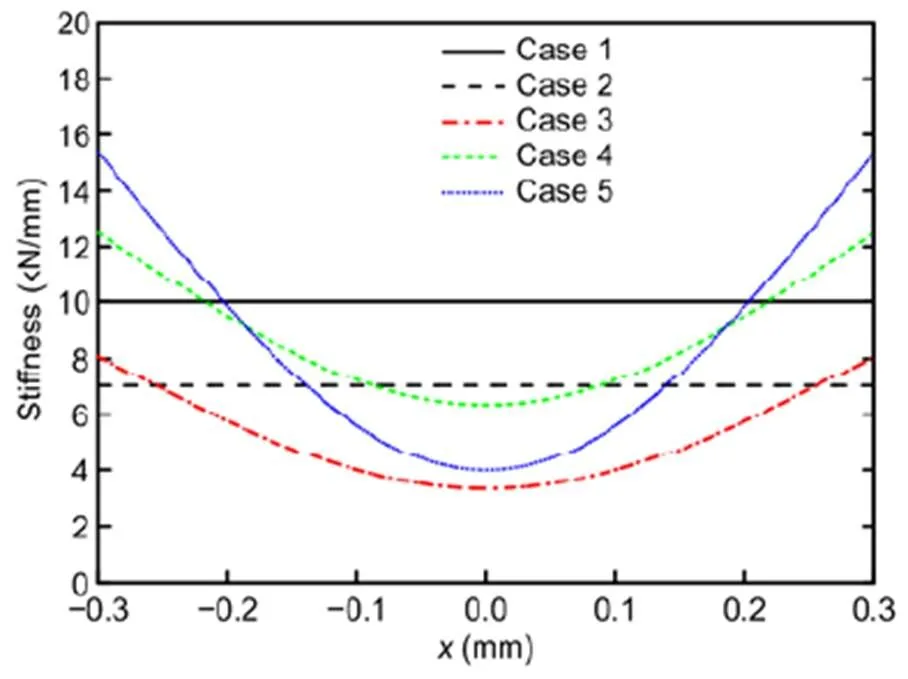
Fig. 6 Stiffness–displacement curves of vibration isolators in cases 1–5
In this study, a four-car train was used for the simulation analysis, with a speed of 80 km/h. The vertical track irregularity was modeled on Grade 5 line (Hamid and Yang, 1981), with wavelengths of 0.1–30.0 m. The vertical track irregularity of rail is shown in Fig. 7.
4.1 Comparison of linear and nonlinear vibration isolators
This study investigated and compared several safety evaluation indicators, including the wheel load reduction ratio and vertical dynamic displacements of the FST. Generally, for safe implementation of the FST (MOHURD, 2012), the maximum vertical displacements of the floating slab and the rail should not exceed 3 mm and 4 mm, respectively. In addition, the wheel load reduction ratio should be less than 0.65.
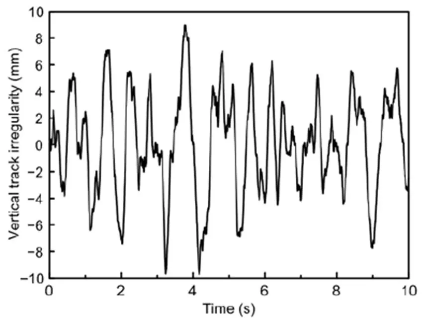
Fig. 7 Time-domain vertical track irregularity
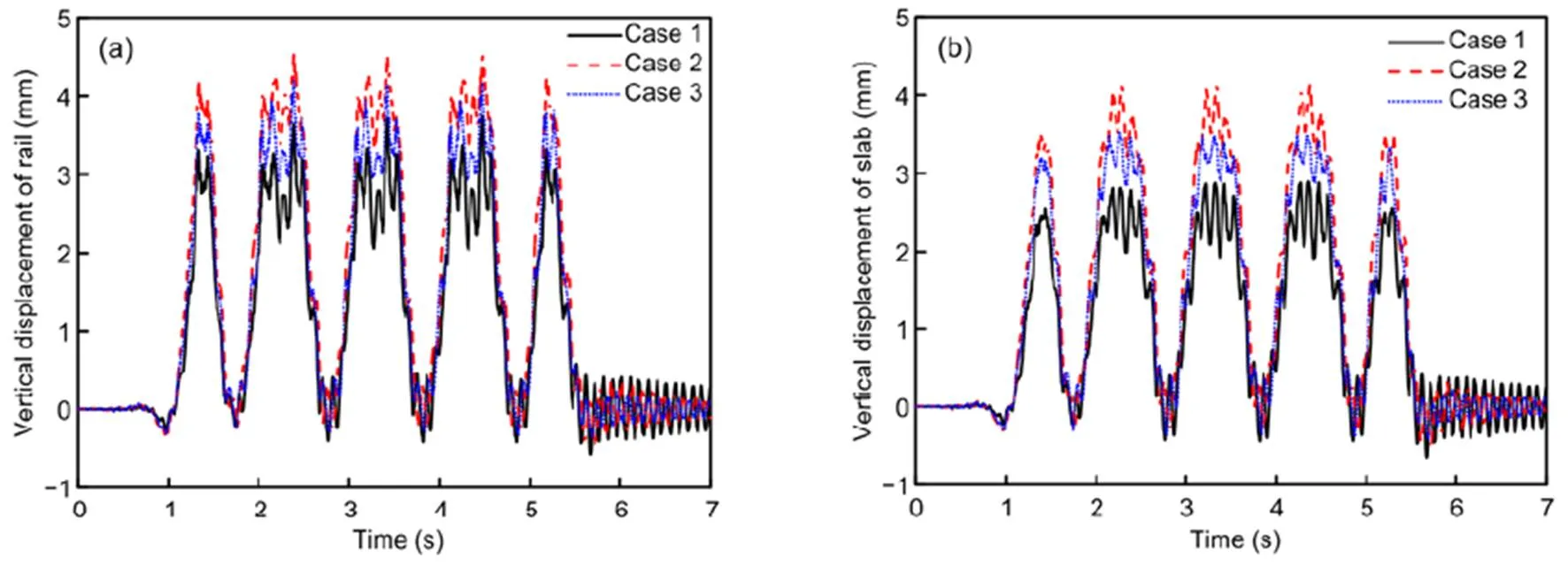
Fig. 8 Vertical dynamic displacements of FST in cases 1–3: (a) rail; (b) floating slab
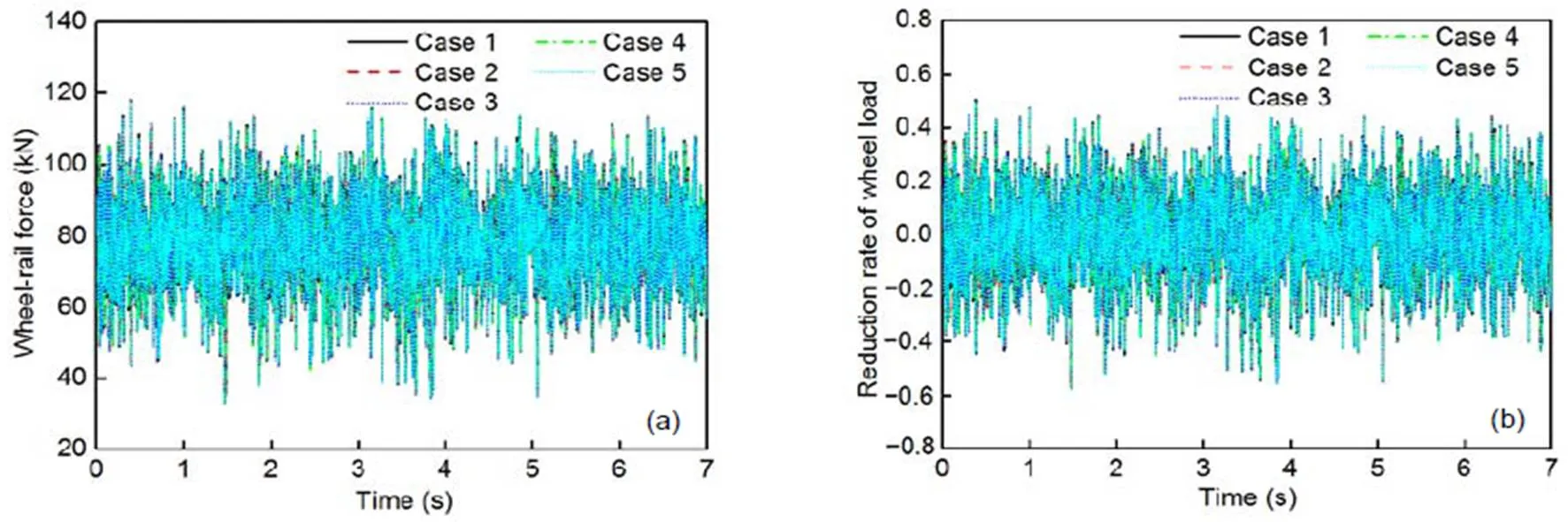
Fig. 9 Time-domain vertical dynamic responses of wheel‒rail system in cases 1–5: (a) wheel‒rail force; (b) wheel load reduction ratio
Fig. 8 shows the vertical dynamic displacements of the FST in cases 1–3. The maximum vertical dynamic displacements of the rail were 3.6 mm, 4.6 mm, and 4.2 mm, respectively, and the maximum vertical displacements of the floating slab were 2.9 mm, 4.1 mm, and 3.5 mm, respectively. Traditional steel spring isolators with stiffness reduction and QZS vibration isolators will increase the vertical displacement of the FST. Fig. 9 shows the time-domain vertical wheel‒rail forces and the wheel load reduction ratios in cases 1–5. The maximum wheel load reduction rates were 0.57, 0.58, 0.57, 0.57, and 0.57, respectively. Thus, the application of QZS isolators in the FST had a negligible influence on the safety of the wheel‒rail system.
The time-domain vertical accelerations and vibration acceleration levels (VALs) of the slab in cases 1–3 are shown in Fig. 10. The time-domain and the frequency-domain vertical supporting forces in cases 1–3 are shown in Fig. 11.
It is evident in Figs. 10 and 11 that reducing the traditional steel spring stiffness or adopting QZS vibration isolators can effectively mitigate the vibration and supporting force of the FST, especially in the low-frequency range. The resonance frequencies reflected in cases 2 and 3 decreased from about 10 Hz to 8 Hz at the 1/3 octave frequency compared to case 1. Moreover, the vertical VALs of the slab in cases 2 and 3 were reduced by 3.7 dB and 4.0 dB, respectively, and the supporting forces decreased by 37% and 35% at the resonance frequency, respectively. However, when a similar vibration reduction effect was achieved with both models, the displacement increment of the QZS-FST was smaller than that of steel spring FST, which is an outstanding advantage of nonlinear stiffness.
4.2 Optimization of PSE and NSE elements
Fig. 12 shows the vertical dynamic displacement of the FST in cases 1, 3, and 4. As expected, when PSE stiffness increased to 15 kN/mm and the stiffness ratio was 0.8, the maximum vertical displacements of the rail and slab were 3.8 mm and 3.0 mm, respectively, which agreed with the conclusion obtained in Section 2.2. Consequently, it is necessary to increase the stiffness of the PSE to meet the safe dynamic displacement limit of the QZS-FST.
The vertical accelerations of the slab and the supporting forces of the FST in cases 1, 3, and 4 were compared, as shown in Figs. 13 and 14. The results indicate the superiority of QZS vibration isolators over traditional linear isolators. The resonance frequency of the slab supported by the QZS vibration isolators decreased from about 10 Hz to 8 Hz at the 1/3 octave frequency as compared to case 1. In addition, the vertical VAL of the slab decreased by 6.9 dB, and the supporting force of the FST decreased by 55%. Thus, in cases 3 and 4, increasing the stiffness of the PSE and appropriately matching stiffness of the NES not only meet the dynamic safety requirement of the wheel‒rail system, but also improve the low-frequency vibration reduction effect of the FST.
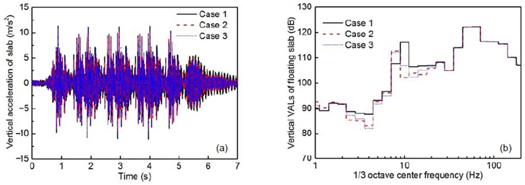
Fig. 10 Vertical dynamic responses of the slab in cases 1–3: (a) time-domain vertical acceleration; (b) frequency- domain vertical acceleration
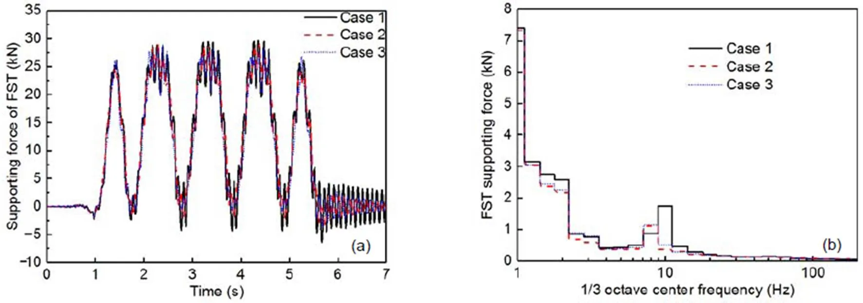
Fig. 11 Vertical dynamic responses of the slab in cases 1−3: (a) time-domain vertical supporting forces; (b) frequency- domain vertical supporting forces
In addition, cases 4 and 5 were contrasted to study the effect of the same bearing capacity and different stiffness nonlinearity levels on the dynamic response of the FST, as shown in Figs. 15–17. The maximum vertical displacements of the rail and slab in case 5 were 3.7 mm and 2.9 mm, respectively, which is basically consistent with the dynamic displacements in case 4.
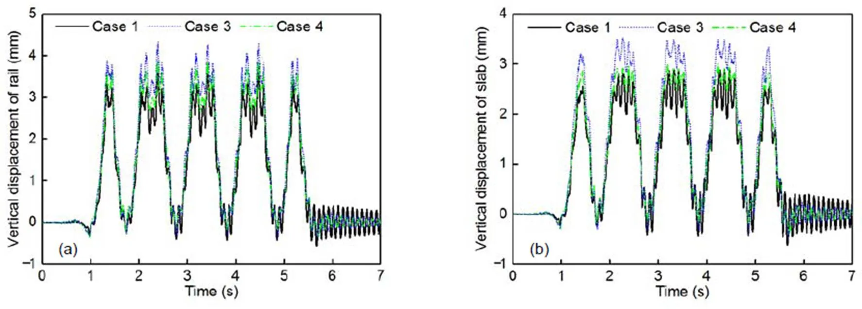
Fig. 12 Dynamic displacements of FST in cases 1, 3, and 4: (a) rail; (b) floating slab
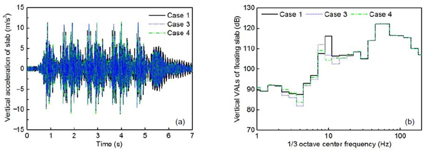
Fig. 13 Dynamic responses of the slab in cases 1, 3, and 4: (a) time-domain vertical acceleration; (b) frequency- domain vertical acceleration
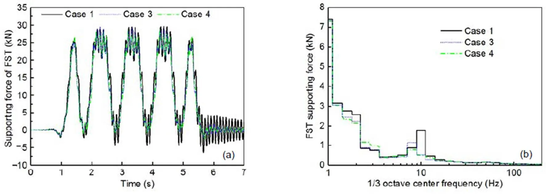
Fig. 14 Supporting forces of FST in cases 1, 3, and 4: (a) time-domain vertical supporting force; (b) frequency-domain vertical supporting force
As shown in Figs. 16 and 17, the vertical vibration accelerations of the slab and the vertical supporting forces of the FST in cases 4 and 5 were analyzed. The vibrations at the resonance frequency of slab in case 5 were chiefly evident in the range of 10.0–12.5 Hz. Compared with traditional steel spring FST in case 1, the vertical VAL of the slab and the supporting force of the slab in case 5 decreased by 4.0 dB and 37%, respectively, at the 1/3 octave frequency of 10.0 Hz. Nevertheless, the vertical VAL of the slab and the supporting force of the FST in case 5 increased by 5.9 dB and 51%, respectively, at the 1/3 octave frequency of 12.5 Hz. An excessive stiffness nonlinearity level of the QZS vibration isolators may amplify the vibrations above the usual natural frequency of the slab. Therefore, the stiffness nonlinearity level should not be too high, taking into consideration the supporting force required for safe dynamic displacement.
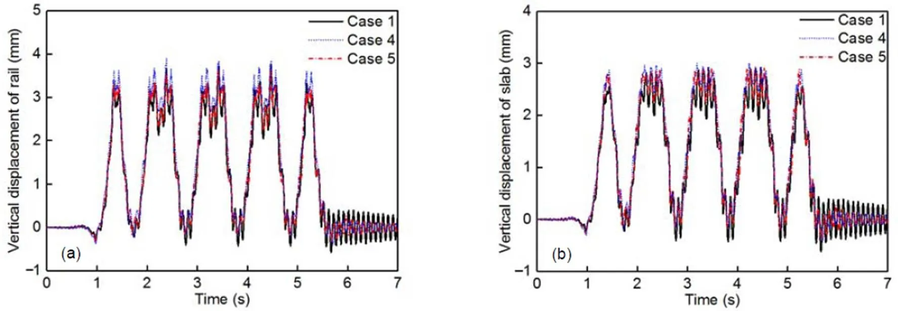
Fig. 15 Dynamic displacements of FST in cases 1, 4, and 5: (a) rail; (b) floating slab
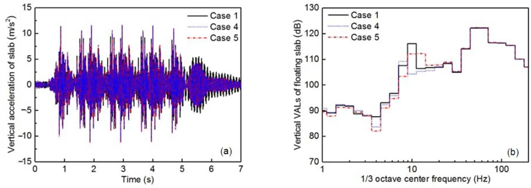
Fig. 16 Dynamic responses of the slab in cases 1, 4, and 5: (a) time-domain vertical acceleration; (b) frequency-domain vertical acceleration
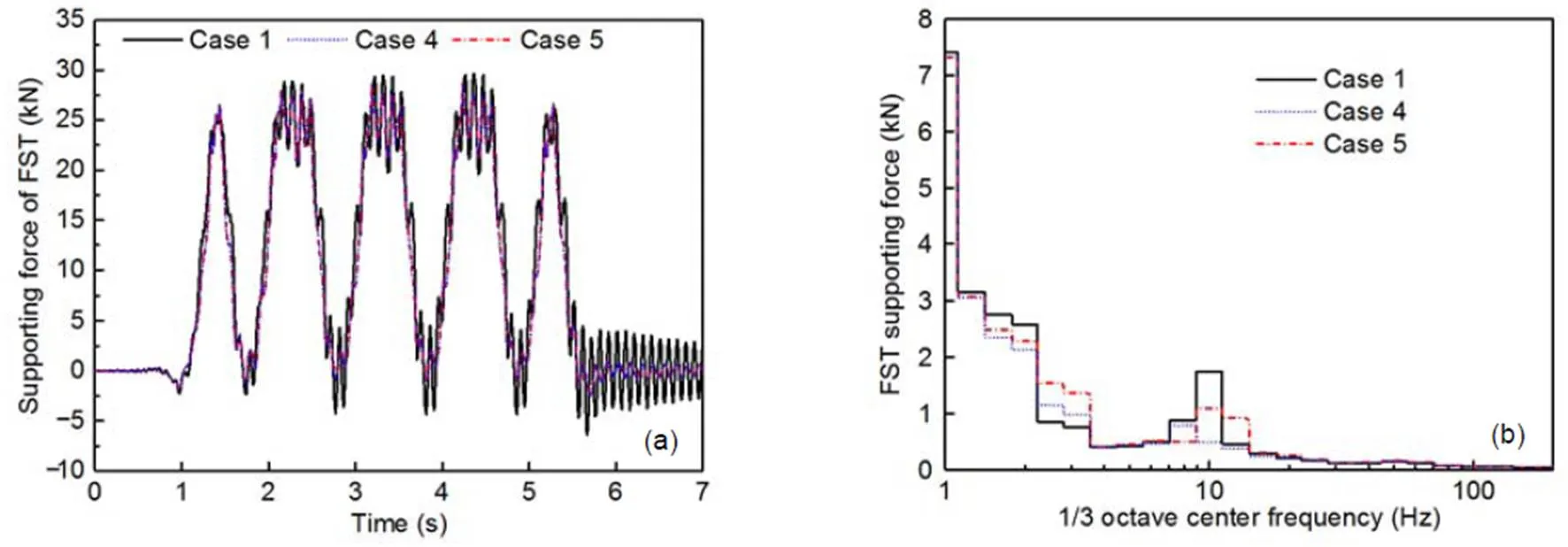
Fig. 17 Supporting forces of the FST in cases 1, 4, and 5: (a) time-domain vertical supporting force; (b) frequency-domain vertical supporting force
5 Conclusions
In this study, QZS vibration isolators were innovatively applied to FST to improve the low- frequency vibration reduction, especially at the natural frequency. For this purpose, some key parameters were studied by considering the dynamic displacement limit of the FST and the dynamic bearing capacity of the QZS vibration isolators. A vertical vehicle‒QZS-FST coupled dynamic model was established to evaluate the influence of nonlinear stiffness on safety and vibration reduction. The main conclusions were:
1. Within the millimeter-level dynamic displacement limit of the FST, the original length of the NSEs chiefly determines the stiffness nonlinearity level. The original length of the NSEs should not be too great, otherwise high-static low-dynamic stiffness cannot be achieved.
2. The compression length of the NSEs at the FST equilibrium position determines the low stiffness of the floating slab with no vehicle load. In addition, to ensure safe dynamic displacement of the FST, the stiffness of the PSE must be increased correspondingly to obtain a higher stiffness at the critical dynamic displacement.
3. Various stiffness groups with different stiffness nonlinearity levels are capable of providing the same bearing capacity and yet have a significantly different vibration reduction effect near the FST natural frequency. When the stiffness nonlinearity level of the QZS vibration isolators is too small, the FST dynamic responses are the same as those of a traditional linear steel spring FST. When the stiffness nonlinearity level of the QZS vibration isolators is too high, the vibration responses at frequencies slightly higher than the natural frequency are amplified.
4. In line with the mechanical characteristics described above, an optimized parameter group of the QZS vibration isolators to support the FST was chosen. Without increasing the dynamic displacement of the floating slab, the resonance frequency was reduced by about 20%, and the vertical VAL and supporting force of the floating slab were reduced by 6.9 dB and 55%, respectively, at the resonance frequency.
In summary, this paper presents a vehicle‒QZS-FST coupled dynamic model simulation analysis which proves theoretically the improvement in low-frequency vibration reduction made possible by QZS vibration isolators. Future research should involve a series of experimental tests to further validate these theoretical conclusions.
Contributors
Ze-ming ZHAO and Kai WEI established the vehicle‒QZS-FST coupled dynamic model. Gao-feng XU processed the corresponding data. After Ze-ming ZHAO and Juan-juan REN accomplished the draft, Ping WANG and Xiang-gang DU helped to improve the manuscript.
Conflict of interest
Ze-ming ZHAO, Kai WEI, Gao-feng XU, Juan-juan REN, Xiang-gang DU, and Ping WANG declared that they have no conflicts of interest.
Carrella A, Brennan MJ, Waters TP, et al., 2008. On the design of a high-static–low-dynamic stiffness isolator using linear mechanical springs and magnets., 315(3):712-720. https://doi.org/10.1016/j.jsv.2008.01.046
Connolly DP, Marecki GP, Kouroussis G, et al., 2016. The growth of railway ground vibration problems–a review., 568:1276-1282. https://doi.org/10.1016/j.scitotenv.2015.09.101
Danh LT, Ahn KK, 2014. Active pneumatic vibration isolation system using negative stiffness structures for a vehicle seat., 333(5):1245-1268. https://doi.org/10.1016/j.jsv.2013.10.027
Dong GX, Zhang XN, Xie SL, et al., 2017. Simulated and experimental studies on a high-static-low-dynamic stiffness isolator using magnetic negative stiffness spring., 86:188-203. https://doi.org/10.1016/j.ymssp.2016.09.040
Gupta S, Degrande G, 2010. Modelling of continuous and discontinuous floating slab tracks in a tunnel using a periodic approach., 329(8): 1101-1125. https://doi.org/10.1016/j.jsv.2009.10.037
Hamid A, Yang TL, 1981. Analytical description of track geometry variations., 838:19-26.
Huang XC, Liu XT, Sun JY, et al., 2014. Vibration isolation characteristics of a nonlinear isolator using Euler buckled beam as negative stiffness corrector: a theoretical and experimental study., 333(4):1132-1148. https://doi.org/10.1016/j.jsv.2013.10.026
Ibrahim RA, 2008. Recent advances in nonlinear passive vibration isolators., 314(3-5):371-452. https://doi.org/10.1016/j.jsv.2008.01.014
Kouroussis G, Zhu SY, Olivier B, et al., 2019. Urban railway ground vibrations induced by localized defects: using dynamic vibration absorbers as a mitigation solution., 20(2):83-97.https://doi.org/10.1631/jzus.A1800651
Kovacic I, Brennan MJ, Waters TP, 2008. A study of a nonlinear vibration isolator with a quasi-zero stiffness characteristic., 315(3):700- 711. https://doi.org/10.1016/j.jsv.2007.12.019
Kuo CM, Huang CH, Chen YY, 2008. Vibration characteristics of floating slab track., 317(3-5):1017-1034. https://doi.org/10.1016/j.jsv.2008.03.051
Lan CC, Yang SA, Wu YS, 2014. Design and experiment of a compact quasi-zero-stiffness isolator capable of a wide range of loads., 333(20): 4843-4858. https://doi.org/10.1016/j.jsv.2014.05.009
Le TD, Ahn KK, 2011. A vibration isolation system in low frequency excitation region using negative stiffness structure for vehicle seat., 330(26):6311-6335. https://doi.org/10.1016/j.jsv.2011.07.039
Le TD, Ahn KK, 2013. Experimental investigation of a vibration isolation system using negative stiffness structure., 70:99-112. https://doi.org/10.1016/j.ijmecsci.2013.02.009
Li YL, Xu DL, 2017. Vibration attenuation of high dimensional quasi-zero stiffness floating raft system., 126:186-195. https://doi.org/10.1016/j.ijmecsci.2017.03.029
Liu CC, Jing XJ, Li FM, 2015. Vibration isolation using a hybrid lever-type isolation system with an X-shape supporting structure., 98:169-177. https://doi.org/10.1016/j.ijmecsci.2015.04.012
Liu XT, Huang XC, Hua HX, 2013. On the characteristics of a quasi-zero stiffness isolator using Euler buckled beam as negative stiffness corrector., 332(14):3359-3376. https://doi.org/10.1016/j.jsv.2012.10.037
Lu ZQ, Brennan MJ, Yang TJ, et al., 2013. An investigation of a two-stage nonlinear vibration isolation system., 332(6):1456-1464. https://doi.org/10.1016/j.jsv.2012.11.019
Ma M, Markine V, Liu WN, et al., 2011. Metro train-induced vibrations on historic buildings in Chengdu, China., 12(10):782-793. https://doi.org/10.1631/jzus.A1100088
MOHURD (Ministry of Housing and Urban-Rural Development of the People’s Republic of China), 2012. Technical Code for Floating Slab Track, CJJ/T 191-2012. MOHURD, Beijing, China (in Chinese).
Shaw AD, Neild SA, Wagg DJ, et al., 2013. A nonlinear spring mechanism incorporating a bistable composite plate for vibration isolation., 332(24):6265-6275. https://doi.org/10.1016/j.jsv.2013.07.016
Ulgen D, Ertugrul OL, Ozkan MY, 2016. Measurement of ground borne vibrations for foundation design and vibration isolation of a high-precision instrument., 93:385-396. https://doi.org/10.1016/j.measurement.2016.07.041
Wei K, Zhao ZM, Du XG, et al., 2019. A theoretical study on the train-induced vibrations of a semi-active magneto- rheological steel-spring floating slab track., 204:703-715. https://doi.org/10.1016/j.conbuildmat.2019.01.210
Xu DL, Yu QP, Zhou QP, et al., 2013. Theoretical and experimental analyses of a nonlinear magnetic vibration isolator with quasi-zero-stiffness characteristic., 332(14):3377-3389. https://doi.org/10.1016/j.jsv.2013.01.034
Yang J, Xiong YP, Xing JT, 2013. Dynamics and power flow behaviour of a nonlinear vibration isolation system with a negative stiffness mechanism., 332(1):167-183. https://doi.org/10.1016/j.jsv.2012.08.010
Yang JJ, Zhu SY, Zhai WM, 2020. A novel dynamics model for railway ballastless track with medium-thick slabs., 78:907-931. https://doi.org/10.1016/j.apm.2019.09.051
Zhai WM, Sun X, 1994. A detailed model for investigating vertical interaction between railway vehicle and track., 23(S1):603-615. https://doi.org/10.1080/00423119308969544
Zhai WM, Xu P, Wei K, 2011. Analysis of vibration reduction characteristics and applicability of steel-spring floating- slab track., 19(4):215- 222. https://doi.org/10.1007/BF03325761
Zhang JZ, Li D, Chen MJ, et al., 2004. An ultra-low frequency parallel connection nonlinear isolator for precision instruments., 257-258:231-238. https://doi.org/10.4028/www.scientific.net/kem.257-258.231
Zheng YS, Zhang XN, Luo YJ, et al., 2018. Analytical study of a quasi-zero stiffness coupling using a torsion magnetic spring with negative stiffness., 100:135-151. https://doi.org/10.1016/j.ymssp.2017.07.028
Zhu SY, Yang JZ, Yan H, et al., 2015. Low-frequency vibration control of floating slab tracks using dynamic vibration absorbers., 53(9):1296- 1314. https://doi.org/10.1080/00423114.2015.1046460
Zhu SY, Wang JW, Cai CB, et al., 2017. Development of a vibration attenuation track at low frequencies for urban rail transit., 32(9):713-726. https://doi.org/10.1111/mice.12285
*Project supported by the National Natural Science Foundation of China (Nos. 51978583, 51425804, 51578468, and 51608460) and the Open Foundation of State Key Laboratory for Track Technology of High-speed Railway (No. 2018YJ180)
© Zhejiang University Press 2021
https://doi.org/10.1631/jzus.A2000040
U213.21
Feb. 8, 2020;
June 23, 2020;
Dec. 15, 2020
 Journal of Zhejiang University-Science A(Applied Physics & Engineering)2021年1期
- Journal of Zhejiang University-Science A(Applied Physics & Engineering)的其它文章
- Dynamic track-soil interaction—calculations and measurements of slab and ballast tracks
- Formation process, key influencing factors, and countermeasures of high-order polygonal wear of locomotive wheels*
- Environmental noise beside an elevated box girder bridge for urban rail transit*
- Mitigation of high-speed trains vibrations by expanded polystyrene blocks in railway embankments*