
Dynamic track-soil interaction—calculations and measurements of slab and ballast tracks
2021-01-13 12:49LutzAUERSCHSamirSAID
Lutz AUERSCH, Samir SAID
Dynamic track-soil interaction—calculations and measurements of slab and ballast tracks
Lutz AUERSCH, Samir SAID
E-mail: lutz.auersch-saworski@bam.de; samir.said@bam.de
The dynamic behaviour of slab and ballast tracks was investigated using measurements and calculations. Hammer impacts and train passages were analysed and measurements were made using geophones (velocity transducers) which had been time-integrated to displacements. The calculations were carried out in the frequency-wavenumber domain for multi-beam- on-continuous soil models. The characteristics of the different tracks and track elements were established in theory and by experiment. The frequency-dependent compliances (displacement transfer functions) showed clear rail-on-railpad resonances or highly damped track-soil resonances. Compared to the rail and sleeper, the track slab had much lower amplitudes. The slab track usually had the highest rail amplitudes due to soft railpads. Train passage yielded track displacements which were a superposition of the axle loads from the two neighbouring axles of a bogie and from the two bogies of two neighbouring carriages. This global behaviour was characteristic of the track slab of the slab track, whereas the rails of the slab and the ballast tracks behaved more locally with only one bogie of influence. The measurements agreed very well with the theory of continuous soil in the case of the six measured slab tracks and acceptably well for the six measured ballast tracks. The measurements allowed us to find appropriate model parameters and to check the models. For example, the Winkler model of the soil was found to be less appropriate because it reacted more locally.
Slab track; Ballast track; Train passage; Hammer impact; Track-soil interaction
1 Introduction
The analysis of dynamic track behaviour has several applications. A track model is useful for the design of tracks (Selig and Waters, 1994; Esveld, 2001; Steenbergen et al., 2007), for understanding the deterioration of tracks (Fröhling, 1997), and for making maintenance decisions (Li and Berggren, 2010). Track measurements can help to identify track parameters (Galvín and Domínguez, 2009; Alves Costa et al., 2012; Connolly et al., 2013; Romero et al., 2013; Kouroussis and Krylov, 2019) and to prevent damage (Bowness et al., 2007; Zhu and Cai, 2014; Ren et al., 2017). Track models can be coupled with vehicle models and the analysis of the vehicle- track interaction yields the dynamic axle loads (Nielsen and Igeland, 1995; Maldonado, 2008; Auersch, 2010). These generate the ground vibrations and establish the ground vibration reduction of special track forms (Jones, 1994; Nelson, 1996; Lombaert et al., 2006b; Auersch, 2012; Zhu et al., 2017).
Fifty years ago, all track models were based on a Winkler soil (Fryba, 1972) consisting of a series of springs. Later, the theory and numerical models for continuous soils and foundations on continuous soils developed rapidly (Wolf, 1985). After the year 2000, many numerical models of railway tracks on continuous soil were published, based on semi-analytical methods (Takemiya and Bian, 2005), wavenumber methods (Jones, 1994; Sheng et al., 1999; Lombaert et al., 2006a; Maldonado, 2008; Auersch, 2012), finite element methods (FEMs) (Ju and Lin, 2008; Connolly et al., 2013; Kouroussis and Krylov, 2019), and boundary element methods (FEBEM) (Auersch, 2005; Romero et al., 2013). The 2.5D method combines a wavenumber approach along the track with an FEM or FEBEM model across the track (Sheng et al., 2006; Galvín et al., 2010; Alves Costa et al., 2012). Whereas some of these methods have been applied to Rayleigh trains, which are as fast as the waves in the soil, in this study we considered only lower train speeds.
Measurements of ballast tracks have been presented by Takemiya and Krylov (2001), de Man (2002), Bowness et al. (2007), Kaewunruen and Remennikov (2007), Galvín and Domínguez (2009), Alves Costa et al. (2012), Connolly et al. (2013), Romero et al. (2013), Arlaud et al. (2016), and Kouroussis and Krylov (2019). Most of these measurements relate to a position on the rail of a ballast track at one site. Maldonado (2008) made measurements at four sites on two slab tracks. Compared to these published measurements, the measurements in this study were more complete: they included all components of slab and ballast tracks at several sites, hammer and train loading, and showed deflection shapes and complete transfer functions (amplitude and phase). There was a wide variety of track measurements. Nevertheless, more track measurements of BAM (Federal Institute of Material Research and Testing) were reported by Auersch (2005).
This paper contains two method sections, Section 2 for the wavenumber domain calculations and Section 3 for the measurement methods, and four results sections. The results are organised as transfer functions (hammer impacts) from theory (Section 4) and from measurement (Section 5), followed by train passages from theory (Section 6) and from measurement (Section 7). The conclusions (Section 8) summarise the characteristics of rails and sleepers of slab and ballast tracks, following impact and train passages in theory and from measurement. Appendix A presents a detailed comparison of measured and calculated slab tracks.
2 Wavenumber domain method for the calculation of ballast and slab tracks
A slab track and a ballast track can both be modelled as multiple-beam systems (Fig. 1). The first beam represents the two rails, the second represents the track slab and the sleepers, and the third beam could be used as an under-ballast plate (Auersch and Krylov, 2019) or the base plate of a floating slab track (Auersch, 2012).
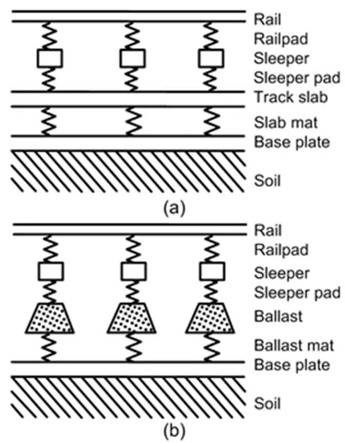
Fig. 1 Multi-beam-on-soil model for a slab track (a) and a ballast track (b)
Each beam is described byEI(the bending stiffness) andm'(the mass per unit track length), which are assembled in a diagonal stiffness matrixand a diagonal mass matrix. The multi-beam system fulfils the set of differential equations for the beam displacementsTunder the track loadTper unit track length.
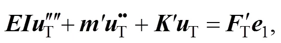
whereis the global stiffness matrix (per unit track length) which includes the dynamic stiffnesses of all track elements, and the base vector1indicates that the force acts on the first beam (the rail). This equation is transformed to the frequency-wavenumber domain:

where=2pis the circular frequency (is the frequency) andis the wavenumber along the track axis. Note that the wavenumber transform of the vertical point loadT()=T() has the constant force amplitudeT.
The dynamic stiffness matrix
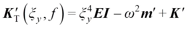
must be coupled with the dynamic stiffness matrix of the soil.
The track beams are connected by elastic track elements: the railpads between the rail and sleeper, the sleeper pads or the contact spring between the sleeper and the ballast, the ballast, and the ballast mat under the ballast or the slab mat between the track slab and the base plate (Fig. 1). The elastic elements are characterized by complex stiffnesses which are assembled in the global stiffness matrix (per unit track length):
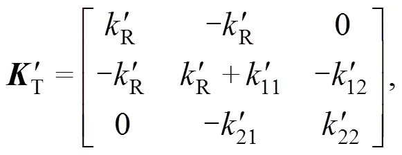
whereRis the railpad stiffness per unit track length andk'(,=1, 2) are the elements of the dynamic stiffness matrixBof the ballast:
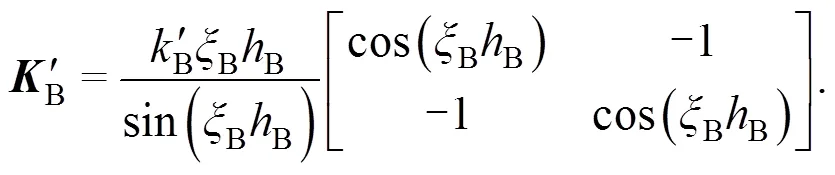
The ballast is described by the static stiffnessBper unit track length, the heightB, and the wavenumberB=/Bof the longitudinal (vertical) wave velocityB. If the ballast is between other elastic elements (the sleeper pads or ballast mat), transfer matrices are used to derive the dynamic stiffness matrix of the pad-ballast-mat support section (Auersch, 2017).
The dynamic stiffness matrix Eq. (3) must be coupled with the dynamic stiffness matrix of the soil, which is calculated as follows. The soil complianceS/S=S(,,) between the displacementSand the stressSof the surface of a homogeneous or layered half-space can be calculated in frequency- wavenumber domain (withandthe wavenumbers across and along the track) by different matrix methods (Wolf, 1985; Auersch, 1994). This complianceSfor plane waves along the soil surface can be integrated across the track to obtain the complianceS/S=S(,) of the track-soil interface for waves along the track:
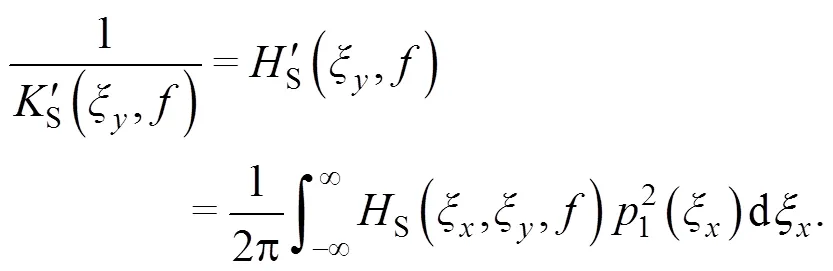
In Eq. (6), the wavenumber transform is:
The wavenumber transform of the uniform load distribution across the track widthhas been used and the average of the response across the track has been taken. The inverse
the soil stiffnessS(,) per unit track length, is used for coupling the soil with the track as
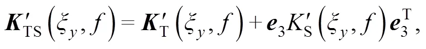
at the last (the third) diagonal matrix element (indicated by the third base vector3), and the dynamic stiffness matrixTS(,) of the track-soil system is established.
The displacements in the frequency-wavenumber domain are calculated by the inversion of this matrix:
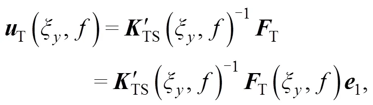
and the wavenumber transformT(,) of the excitation force on top of the track. Finally, the displacement distribution along the track can be calculated by the Fourier integral of the wavenumber domain solution:
(11)
The details of the numerical integration of this equation are reported by Auersch (2017). The solution Eq. (11) holds for a symmetric pair of point loads. It could be extended to an antimetric pair of point loads as given by Lombaert et al. (2006b) and Maldonado (2008), but the main interest in vehicle-track-soil interaction is in symmetric wheelset loads.
3 Methods for the measurement of train passages and hammer impacts
Track vibrations during hammer impacts and the passage of trains (Fig. 2) were measured with velocity transducers (geophones). The geophone measurement data were corrected for the frequency-dependent complex transfer function of the geophones (eigen frequency 4.5 Hz) and then time-integrated to obtain the displacements of the track elements. In addition, a base-line correction was necessary (please refer to Milne et al. (2018) for a similar procedure).
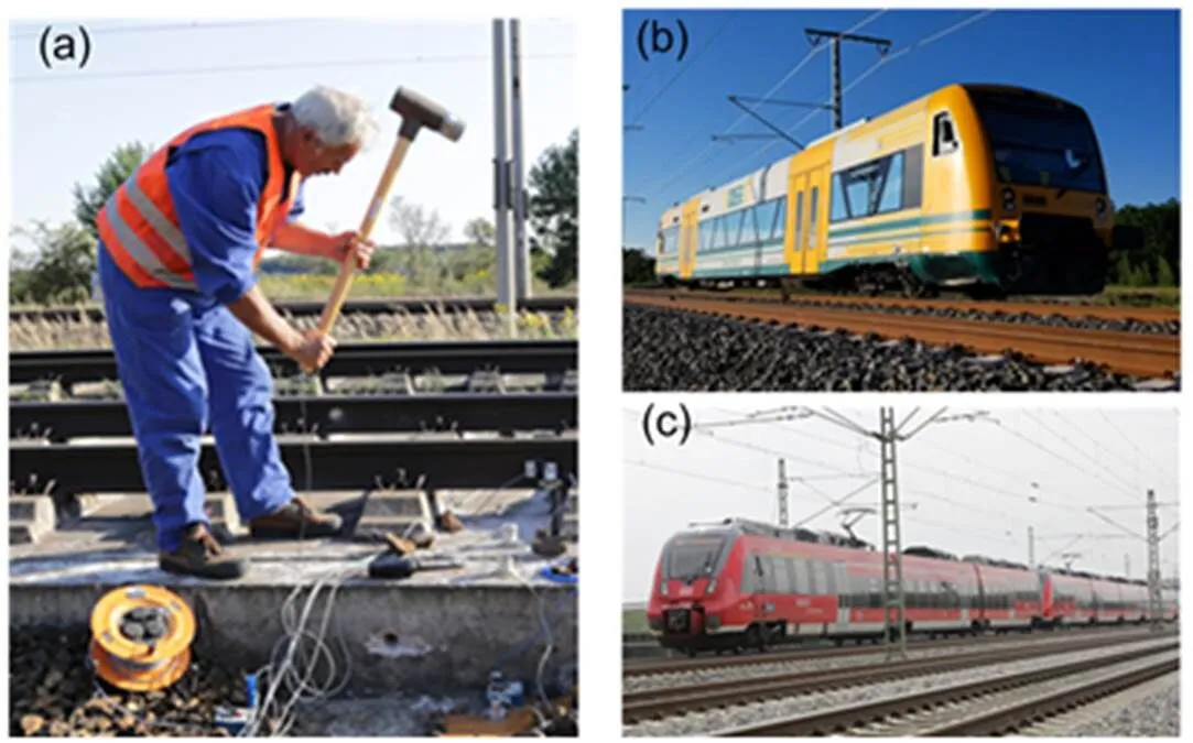
Fig. 2 Measurements of the dynamic track behaviour due to hammer impacts (a) and train passages (b and c)
Using an instrumented hammer, the transfer functions of the track and of the soil can be evaluated. The impact on the right rail, the left rail or both can be measured to give a one-rail transfer function of the track. Averaging the transfer functions from the left and right rail impacts yields the two-rail transfer function of the track under a wheelset load, which is the main interest of the vehicle-track-soil interaction analysis. Instead of averaging the left and right rail impacts, it is also possible to average the left and right side responses to a single side impact. Taking half of the one-rail transfer function yields an acceptable approximation of the two-rail transfer function for the rail. The observed correction factors (two-rail to one-rail transfer function) for the other track elements were between 0.5 and 0.8. In this study, the original one-rail measurement results are presented, and a reduction to the two-rail transfer function must be observed.
Hammer impacts and a measurement line on the soil were used to determine the wave velocities and the damping of the different soils whenever space and time were available (Auersch and Said, 2015). Some shear wave velocities of the measuring sites are given in Tables 1 and 2. Most of the sites are on medium soft soil (glacial sand and marl) in northern Germany. Two sites (sites D and H) are on fluvial deposits (sand) in southern Germany, and only site G has near-surface rock material.
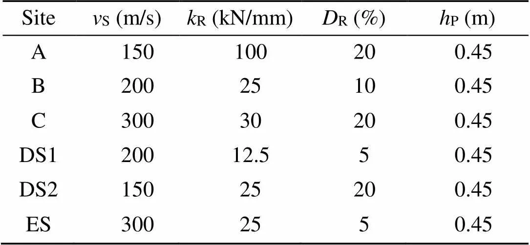
Table 1 Parameters of the measured slab tracks
S: soil shear wave velocity;R: railpad stiffness;R: railpad damping;P: thickness of the slab
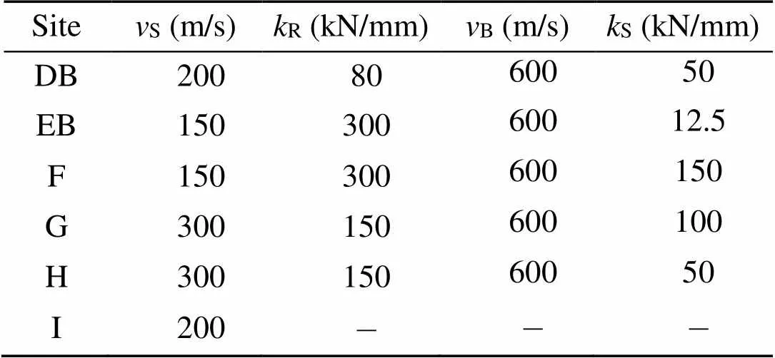
Table 2 Parameters of the measured ballast tracks
B: ballast longitudinal wave velocity;S: contact stiffness
4 Theoretical results for hammer impacts– transfer functions of the track
Slab track and ballast track models were calculated using the wavenumber domain method. The standard track parameters given in Table 3 apply throughout this study unless otherwise stated. Frequency-dependent complex compliances/() were calculated for a two-rail wheelset excitation in the frequency range of 0–150 Hz, which is typical for the track-soil interaction. The complex compliances are presented as amplitude phase in Figs. 3–7.
The transfer functions of the rail of the slab track in Fig. 3a clearly show the strong influence of the elastic railpad. The static compliance can be above 1×10⁻⁸m/N (=10×10−9m/N), which means 1 mm displacement per 100 kN axle load. Rail-on-railpad resonances appear at 85 and 120 Hz for railpads ofR=10 and 20 kN/mm. The resonance amplitudes reach compliance values of 4×10⁻⁸m/N. The resonances can also be found in the response of the track slab (Fig. 3b), but with smaller amplitudes. The slab amplitudes are much smaller than the rail amplitudes, and the difference can be more than 1×10⁻⁸m/N. The low-frequency compliance of the slab is determined mainly by the stiffness of the soil.
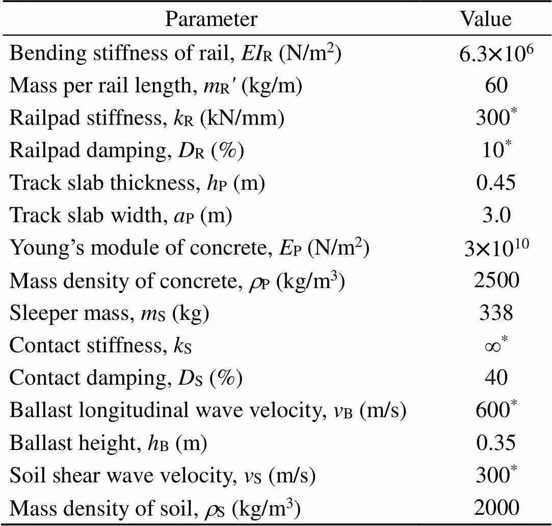
Table 3 Standard parameters of the calculated slab and ballast tracks
Note: the values marked with*were varied
The behaviour of the ballast tracks is simpler, as the differences between the rail and sleeper are usually small. This can be seen in Fig. 4, for the stiff railpads. The medium stiff railpads yield a rail-on- railpad resonance at about 150 Hz and higher static compliances. The realistic stiff railpads have no resonance (up to 150 Hz) and lower static compliances. The sleeper compliances (Fig. 4b) are similar and are determined by the soil. The softest railpad yields the lowest sleeper displacement because of a wider load distribution. The sleeper and rail displacements were more similar for the stiff railpads. These stiff railpads ofR=300 kN/mm were used as a standard for the ballast track.
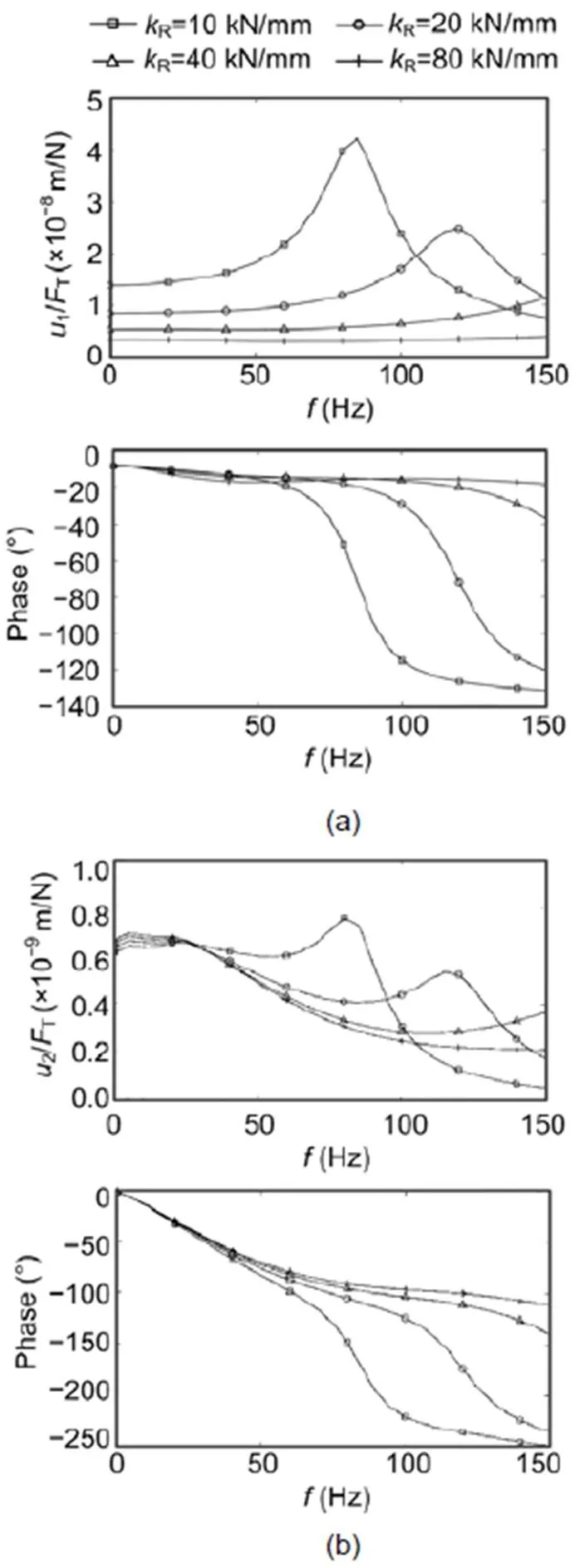
Fig. 3 Calculated frequency-dependent compliances of slab tracks, represented as amplitude (top) and phase (bottom), with the variation of the railpad stiffness: (a) rail; (b) track slab
The influence of the soil on the ballast track is shown in Fig. 5. The maximum effect can be seen at the low frequencies where the compliance is determined by the soil. The compliances reach almost 1×10⁻⁸m/N for the softest soil. The softest soil results also in the strongest phase delay at the low frequencies. For higher frequencies, the transfer functions of the ballast tracks on different soils are more similar at lower amplitudes. Due to the continuous soil, the stiffness of a ballast track turns from soft to stiff as frequencies increase.
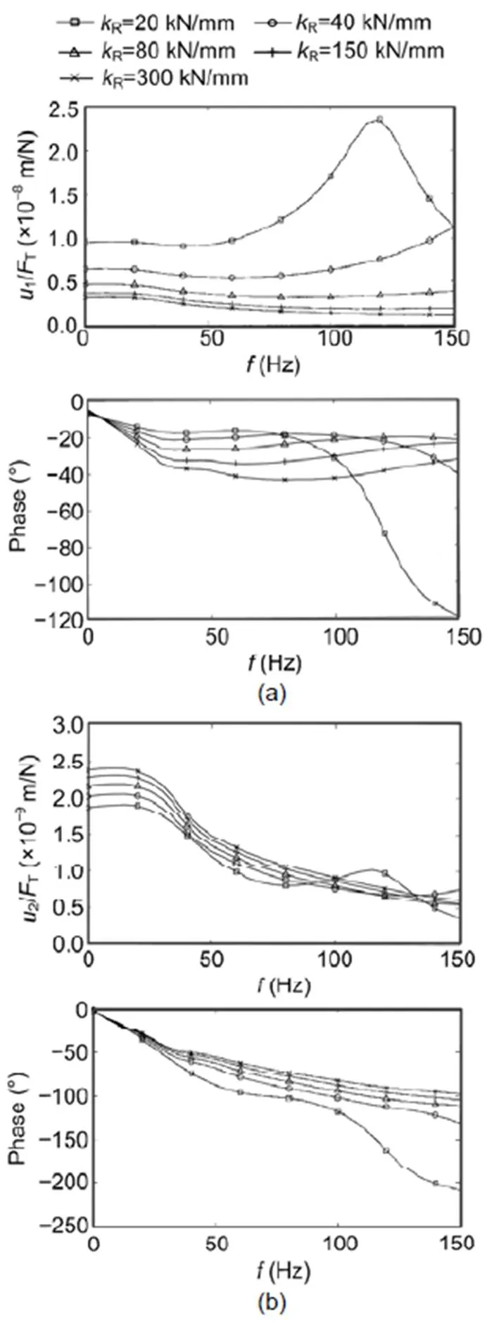
Fig. 4 Calculated frequency-dependent compliances of ballast tracks, represented as amplitude (top) and phase (bottom), with the variation of the railpad stiffness: (a) rail; (b) sleeper
Whereas the soil has the strongest influence at lower frequencies, the ballast has its strongest influence at higher frequencies (Fig. 6). The softest ballast yields a small resonance at 100 Hz together with the sleeper and rail mass. The ballast material can be soft, but also, the contact between the ballast and the concrete sleeper can be soft due to the small number of ballast stones which are in contact with the sleeper. The effect of such a soft contact between the ballast and sleeper is shown in Fig. 7. The contact stiffness yields higher low-frequency compliances of up to 2×10⁻⁸m/N. According to the assumed contact spring stiffness, a drop of amplitudes and phases starts at frequencies between 25 and 100 Hz. This phenomenon could be attributed to a highly-damped resonance of the sleeper and rail mass on the contact spring.
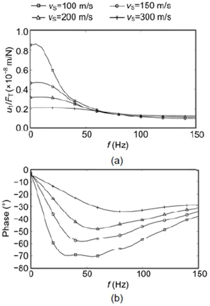
Fig. 5 Calculated frequency-dependent compliances of the rail of ballast tracks, with the variation of the wave velocity of the soil: (a) amplitude; (b) phase
5 Measured results for hammer impacts– transfer functions of the track
Results for six different slab tracks at six different sites are presented in Fig. 8. Fig. 8a shows the transfer functions of the rail, and Fig. 8b the transfer functions of the track slab (or the sleeper). In Fig. 9 (p.28), these measurement results are compared with similar results from calculations with the appropriate parameters of Table 1. A detailed comparison between measurement and theory can be found in Appendix A. For such a comparison it must be noted that the compliance of the track is higher for the asymmetric hammer impact measurements on one rail than for the symmetric wheelset excitation on two rails of the calculation.
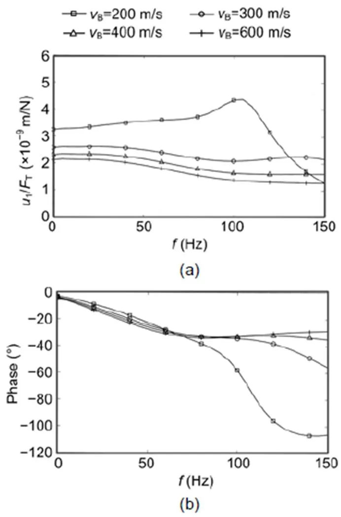
Fig. 6 Calculated frequency-dependent compliances of the rail of ballast tracks, with the variation of the wave velocity of the ballast: (a) amplitude; (b) phase
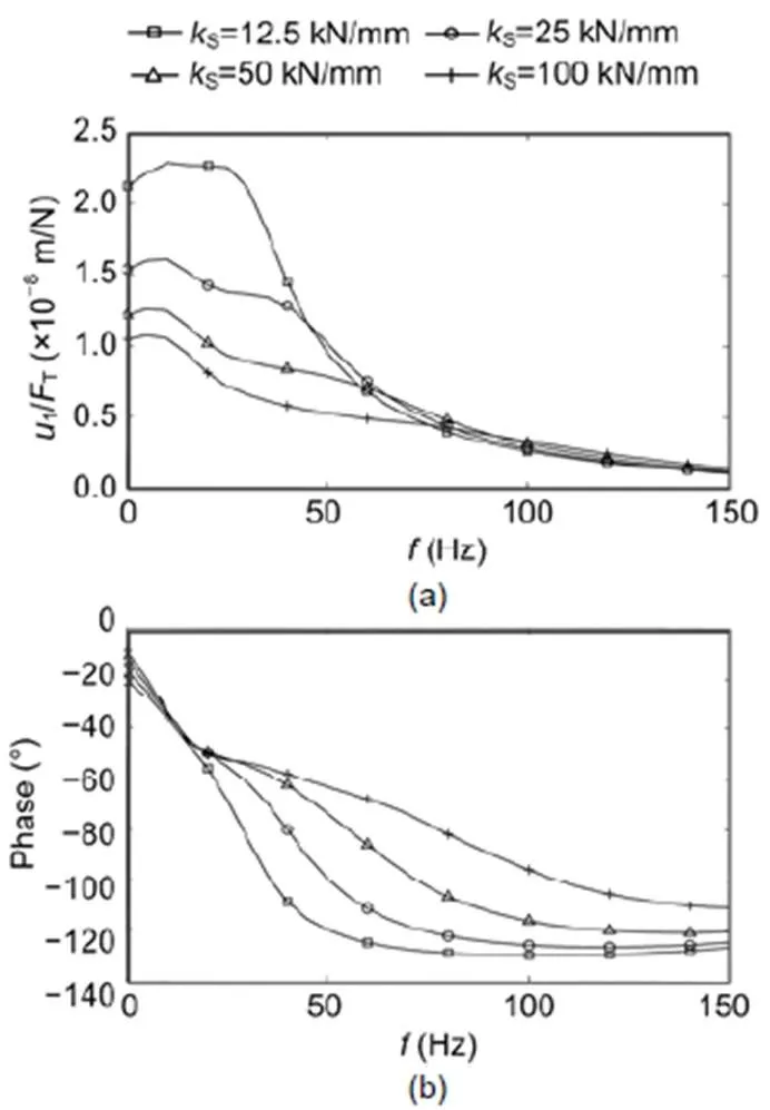
Fig. 7 Calculated frequency-dependent compliances of the rail of ballast tracks, with the variation of the contact stiffness between ballast and sleepers: (a) amplitude; (b) phase
The most characteristic items of the rail of the slab tracks (Fig. 8a) are the resonances of the rail on the railpad. Four of the slab tracks had nearly the same resonance at 140 Hz, indicated also by a crossing of four phase curves at −90°. Site C had its resonance at 215 Hz (above the plotted frequency range), and site DS1 had a lower resonance at 90 Hz due to very soft railpads. The rail-on-railpad resonance could also be found on the track slab, but not so clearly and with an anti-phase (for example, see site DS1 with the lowest resonance frequency of 90 Hz and a strong phase drop). The phases decreased linearly at low frequencies, reaching an asymptotic value of −130° before they dropped down due to the rail-on-railpad resonance at high frequencies. The static compliances of the rail were between 1×10⁻⁸and 2×10⁻⁸m/N, and of the track slab between 1×10⁻⁹and 4×10⁻⁹m/N, which is about one tenth of the rail compliances. The compliance of the rail depended on the stiffness of the railpad, whereas the compliance of the track slab depended on the stiffness of the soil. This corresponds well with the calculated results in Fig. 9 in which the railpad as well as the soil was varied.
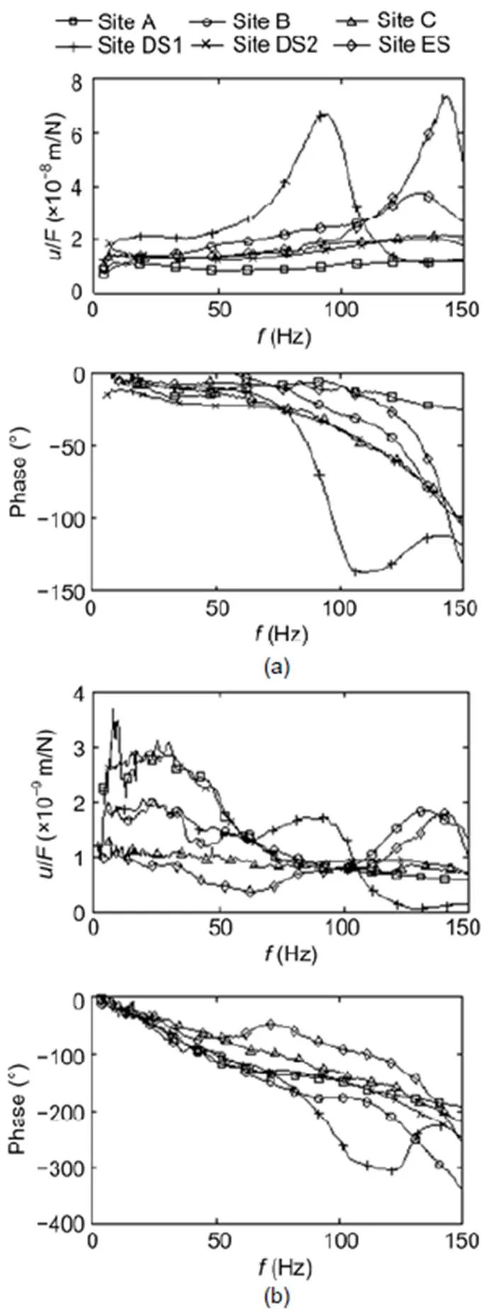
Fig. 8 Measured one-rail frequency-dependent compliances of six slab tracks, represented as amplitude (top) and phase (bottom): (a) rail; (b) track slab
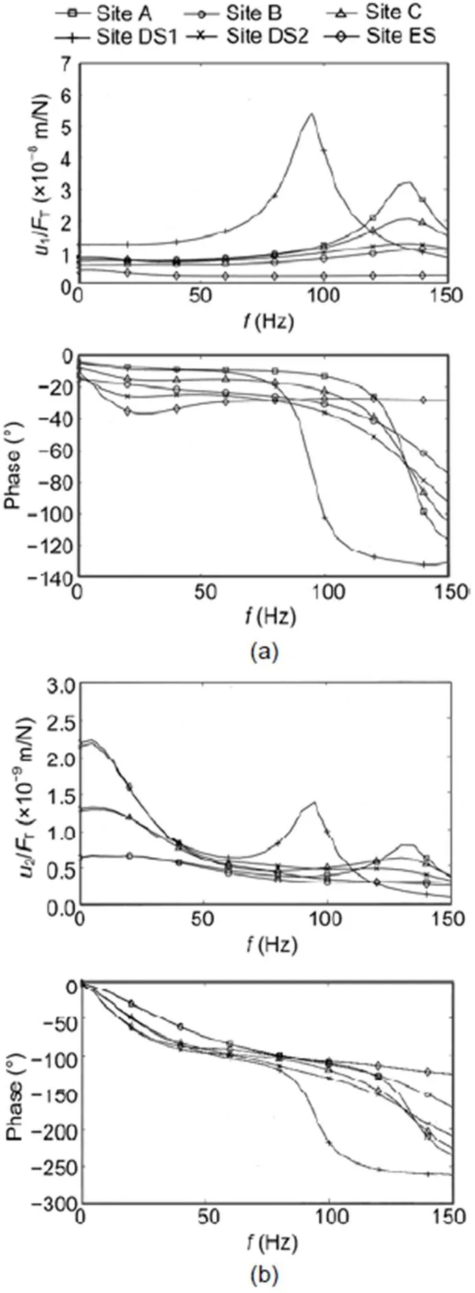
Fig. 9 Calculated two-rail frequency-dependent compliances of six slab tracks, represented as amplitude (top) and phase (bottom): (a) rail; (b) track slab
Corresponding results for the rail and sleeper compliances measured at five ballast tracks are presented in Fig. 10. The transfer functions varied considerably from site to site. The static compliances were in the range of 7×10⁻⁹(at site G) to 3×10⁻⁸m/N (at site EB). The compliances were determined by the stiffness of the soil or the stiffness of the ballast.No resonance amplification occurred up to 150 Hz. A strong drop in the amplitudes was found at frequencies of 40 Hz (at site DB), 50 Hz (at site EB), 60 Hz (at site H), 70 Hz (at site G), and 120 Hz (at site F). The strong drop in amplitudes was accompanied by a strong drop in the phase. This indicates a strongly damped resonance of the track-soil system. The small difference between the rail and the sleeper amplitudes indicates a stiff railpad which does not yield a rail-on-railpad resonance below 150 Hz. The phase of the sleeper was a little lower (more negative) than the phase of the rail. All these details can also be found in the calculated results for the ballast track in Fig. 11, which are based on the roughly approximating parameters of Table 3. To cover the high low-frequency amplitudes, it is necessary to include a soft element in the model. In this study, a soft contact stiffness between the ballast and sleeper was assumed. Depending on the contact stiffness, different amplitudes and different cut-off frequencies were observed in agreement with the experimental results.
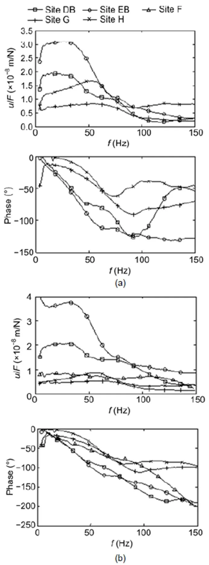
Fig. 10 Measured one-rail frequency-dependent compliances of five ballast tracks, represented as amplitude (top) and phase (bottom): (a) rail; (b) sleeper
6 Theoretical results for train passages
In Figs. 12 and 13, the responses of the slab and ballast track are presented for the most important parameter variations. The displacement histories of the rail and slab of the slab track, and for the rail and the sleeper of the ballast track, are shown for the passage of four bogies where the axle load is 100 kN and the train speed is 160 km/h. The rail displacements of the slab track are ruled by the railpad stiffnesses (Fig. 12a), whereas the displacements of the ballast track are ruled by the soil stiffness (Fig. 13a). The results for the maximum static displacements are the same for the transfer function as for the quasi- static passage of a single axle. The displacement of 1 mm for an axle load of 100 kN is the same as a compliance of 1 mm/100 kN=1×10⁻⁸m/N. As an axle load also has an influence on the neighbouring axle, the displacements for a train passage are somewhat greater than for a single axle. If this effect is strong, the track behaves more globally; if the effect is small, the track behaves locally (the displacements under an axle are influenced only by the load of that axle).
Whereas the transfer functions show the dependency on frequency, the time histories of train passages show the static displacements along the track. The rail of the slab track (Fig. 12a) and the rail of the ballast track (Fig. 13a) both react locally. The sleeper of the ballast track (Fig. 13b) reacts less locally, and the slab of the slab track (Fig. 12b) has the most global reaction of all tracks and components. The global behaviour of the track slab yields a trough of displacement for the whole bogie, whereas all other elements show pulses for each axle. If rail and sleeper/slab are plotted together as in Figs. 12c, 12d and 13c, 13d, a strong difference can be found for the slab track with the soft railpad (Fig. 12d). The ballast track displacement shows minor differences between the rail and sleeper (Fig. 13c), which are almost constant d»0.1 mm for the railpad stiffness ofR= 300 kN/mm, independent of the soil stiffness.
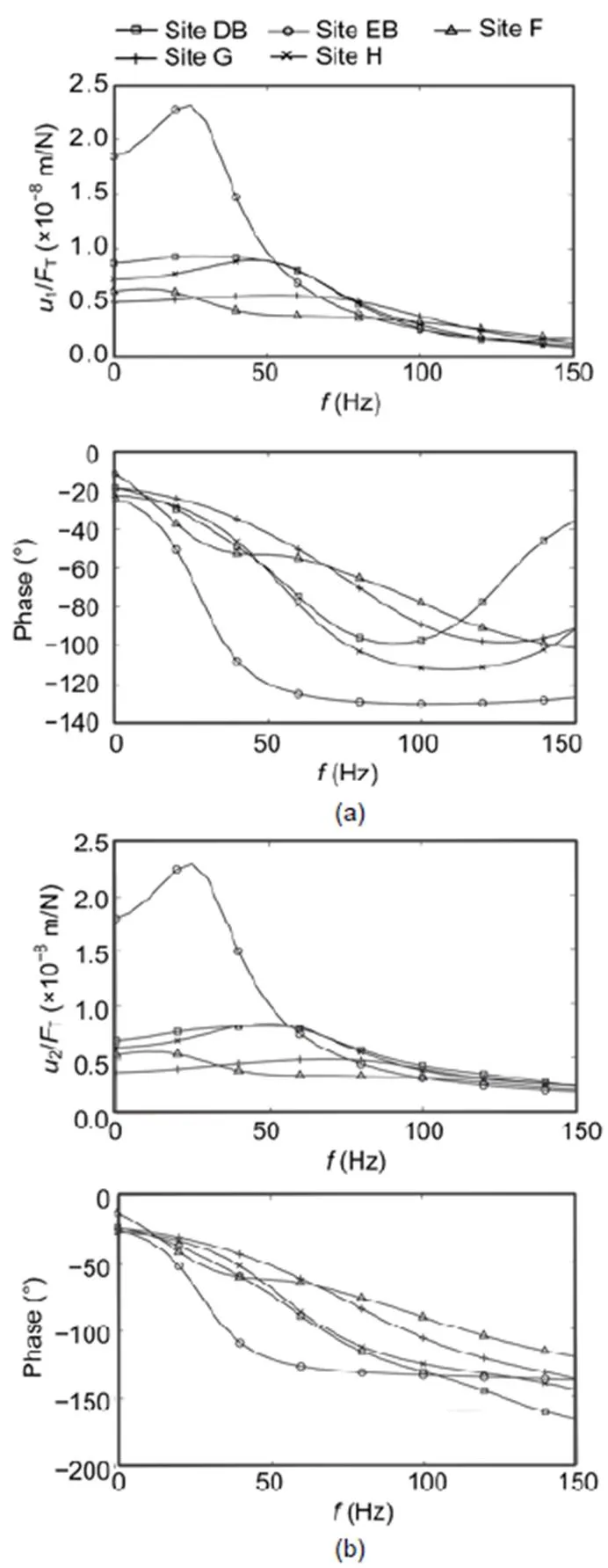
Fig. 11 Calculated two-rail frequency-dependent compliances of five ballast tracks, represented as amplitude (top) and phase (bottom): (a) rail; (b) sleeper
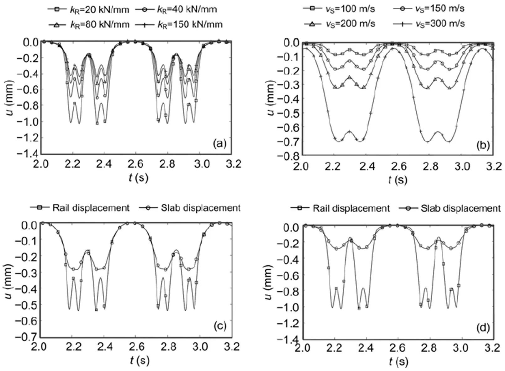
Fig. 12 Calculated train passages (one carriage+two half carriages) over slab tracks
Rail displacements (a) for different railpad stiffnesses; Slab displacements (b) for different wave velocities of the soil; Rail and slab displacements forR=80 kN/mm (c) andR=20 kN/mm (d)
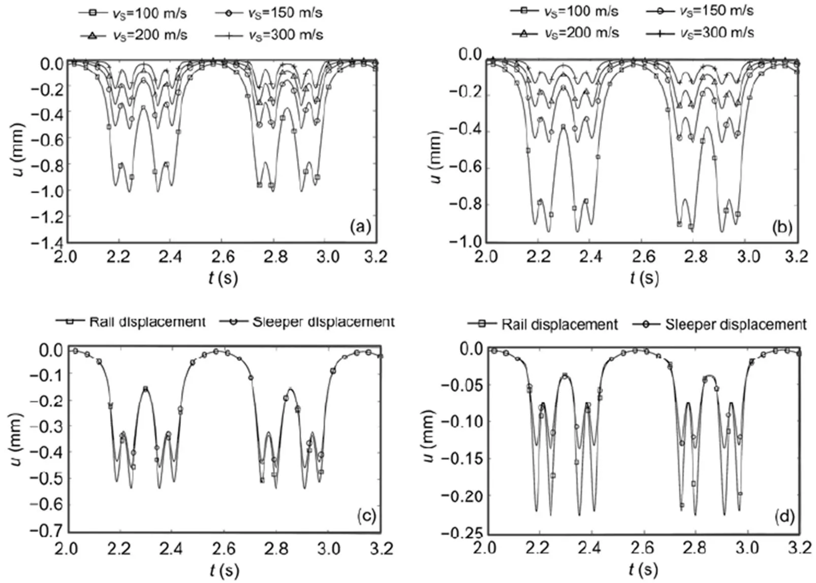
Fig. 13 Calculated train passages (one carriage+two half carriages) over ballast tracks
Rail displacements (a) and sleeper displacements (b) for different wave velocities of the soil; Rail and sleeper displacements forS=150 m/s (c) andS=300 m/s (d)
Local or global behaviour can be observed from the displacements between two axles or between two bogies. Higher inter-axle and inter-bogie displacements indicate a more global behaviour. A zero inter-axle displacement would mean that the neighbouring axles have no influence on the midpoint between them. The following values have been observed and translated to relative displacements. In Figs. 12c and 13c, the rail has the same maximum displacement of 0.5 mm for the slab and the ballast track. In that case, the inter-axle displacements have the same value of 0.35 mm (70%) and the inter-bogie displacements are at 0.2 mm (40%). The sleeper of the ballast track has the same absolute displacements, but due to the smaller maximum of 0.43 mm, the relative values are higher (80% and 47%, respectively). The track slab of the slab track behaves completely differently. There is no separate inter-axle displacement (100%, 0.3 mm) and the inter-bogie displacement (70%) is higher than that of the rail. In the case of softer railpads or softer soils (Figs. 12a and 13a) the behaviour becomes more global as shown by the higher inter-axle displacements.
Note that the Winkler model of the track soil system cannot represent the global behaviour of the ballast track or of the track slab of the slab track. As the Winkler soil, by definition, reacts locally to any load, it can behave only locally, which means with sharper pulses and small lift-ups which were not observed in the present measurements (Auersch, 2005, 2017).
7 Measurement results for train passages
Passages of intercity express (ICE) trains were measured at all six slab track sites (Fig. 14) and at four ballast track sites (Fig. 15). The axle loads (130–160 kN) were somewhat higher than the calculated load of 100 kN. The time histories were not as regular as for the calculations with static loads because the measurements also included the response to small dynamic train loads (for example from track irregularities). The highest amplitudes, in the range of 0.7 to 1.5 mm, were found for the slab track rails. This was due to the soft and very soft railpads used in the slab tracks. The displacements of the rails of the ballast tracks ranged from 0.5 to 1.0 mm. The high values were due to the relatively soft railpads at the sites DB and H. The difference between the rail and sleeper of a ballast track is usually small, but due to the softer railpads, this difference reached 0.5 mm. The absolute sleeper displacements were between 0.3 and 0.5 mm. In contrast, for the slab track, the sleeper or slab amplitudes were much smaller than the rail amplitudes (up to 1.1 mm difference). The displacement ranged from 0.15 to 0.4 mm due to the different soil stiffnesses. The differences between the rail and the sleeper or track slab amplitudes indicate the stiffness of the railpad. The differences were between 0.5 and 1.1 mm for the measured slab tracks with soft railpads, between 0.2 and 0.3 mm for the slab tracks with medium railpads, and between 0.15 and 0.5 mm for the measured ballast tracks with medium to stiff railpads.
The ballast track at site G also had smaller displacements, which can be explained by the stiffest soil of all sites with a measured wave velocity ofS=300 m/s. A stiff soil yields smaller amplitudes and a more local behaviour with sharper axle pulses. Sharp axle pulses were also found for the slab track rail at site A. All other slab track rails had less sharp axle pulses due to the very soft railpads. The railpads of ballast tracks are usually stiffer, but the axle pulses showed a similar global behaviour as those of the slab track due to the soft support provided by the sleepers on the soil. All ballast track sleepers showed smaller axle pulses and a more global behaviour than the ballast track rails. The track slabs of the slab tracks showed the most global behaviour with only a smooth bogie pulse, but no axle pulses. These different global behaviours can also be quantified by the inter-axle and the inter-bogie displacements. The strongest global behaviour of the track slab showed 100% inter-axle displacements and 50% to 90% inter-bogie displacements. The other components had almost zero inter-bogie displacements (i.e. separated bogie pulses). The inter-axle displacements of the ballast track sleepers (60% to 90%) were a little higher than those of the rails (50% to 80%).
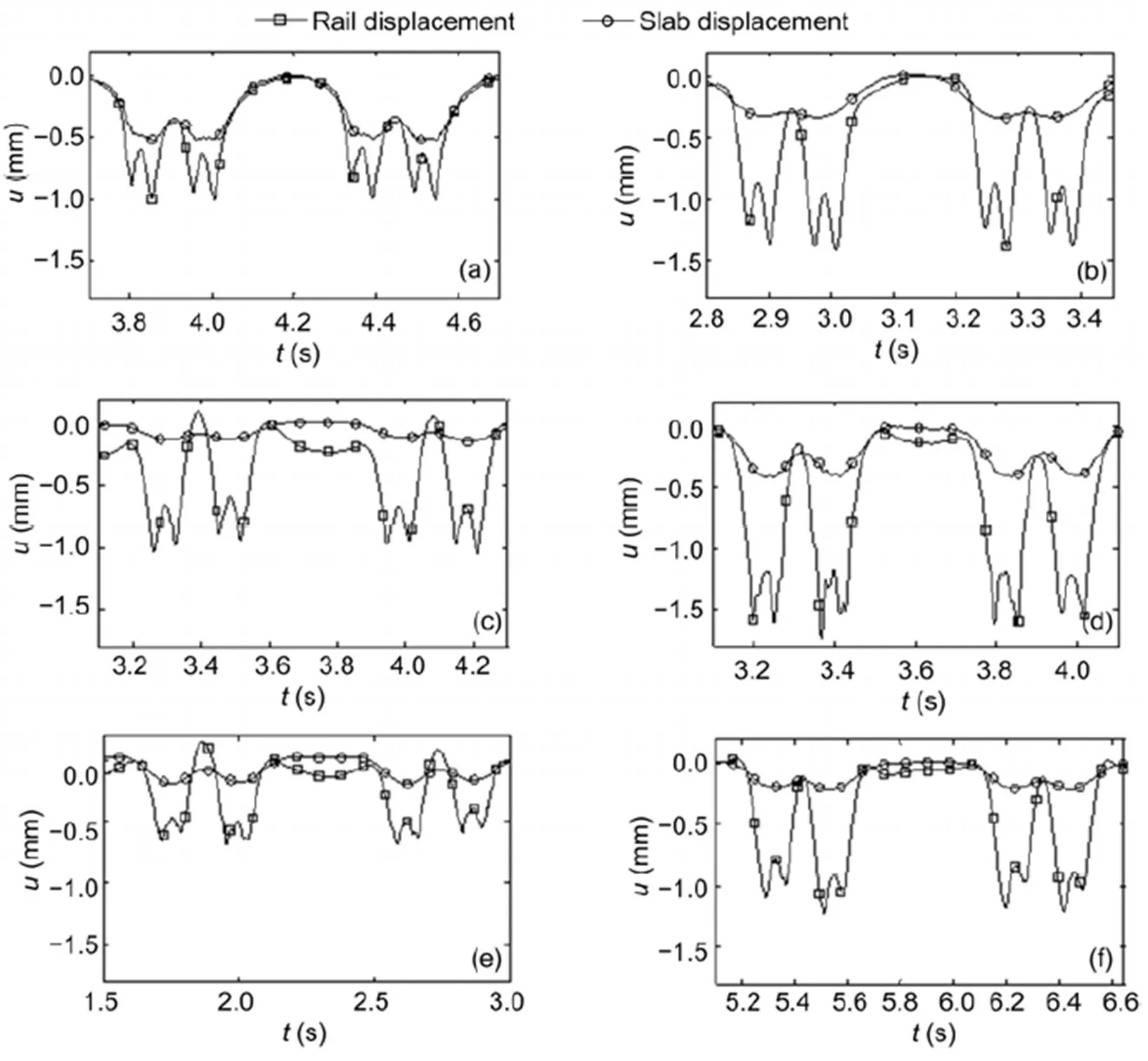
Fig. 14 Measured train passages (one carriage+two half carriages) over slab tracks
Rail and slab displacements at sites A (a), B (b), C (c), DS1 (d), DS2 (e), and ES (f)
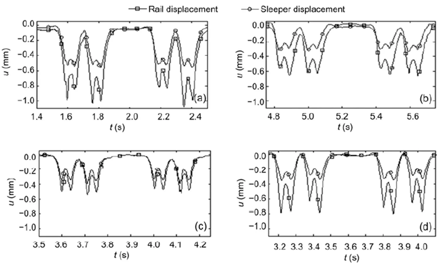
Fig. 15 Measured train passages (one carriage+two half carriages) over ballast tracks
Rail and sleeper displacements at sites DB (a), EB (b), G (c), and H (d)
All these characteristics of train passages are in good agreement with the theoretical results of Section 6, if the higher static axle loads of the ICE trains are considered. Results for other trains are shown in Fig. 16. A very short regional train consisting of only one carriage was measured at site I (Figs. 2b and 16a). The measured sleeper displacement of 0.4 mm was in the range of the sleeper displacements of the other ballast tracks. At site H another regional train was measured consisting of two units of five carriages, with two carriages sharing one bogie (Figs. 2c and 16b). The rather high rail amplitudes of 0.9 mm were due to the higher axle load and the rather soft railpads.
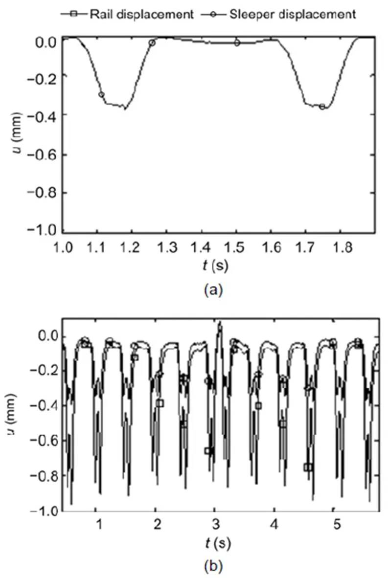
Fig. 16 Measured rail and sleeper displacements of different trains over ballast tracks at: (a) site I, short regional train with a single carriage; (b) site H, regional train of 10 cars with shared bogies
8 Conclusions
The dynamic behaviour of slab and ballast tracks was analysed by frequency-wavenumber domain calculations and by measurements of hammer impacts and train passages. The compliances of the different tracks and track elements were analysed as frequency-dependent transfer functions and as distributions along the track. Clear resonances were observed for the rail on a soft railpad in the case of the slab track. The measured strong drop in amplitudes and phases could be explained by the highly damped track-ballast or track-soil resonances of the ballast track. Namely, a soft contact between ballast and sleepers was assumed. There was a strong influence of the soil on the low-frequency behaviour of the ballast track and the track slab. The track slab of the slab track had the smallest compliance and the most global deformation of all track elements, whereas the rail of the slab track had the greatest compliance and the most local deformation. The measurement results agreed well with the calculated results in general, but also in many details if appropriate parameters were chosen for the track models.
Contributors
Lutz AUERSCH developed the software, performed the calculations, made some of the measurements, and wrote the article. Samir SAID performed all other measurements and evaluations.
Conflict of interest
Lutz AUERSCH and Samir SAID declare that they have no conflict of interest.
Alves Costa PA, Calçada R, Cardoso AS, 2012. Track-ground vibrations induced by railway traffic: in-situ measurements and validation of a 2.5D FEM-BEM model., 32(1):111-128. https://doi.org/10.1016/j.soildyn.2011.09.002
Arlaud E, D’Aguiar SC, Balmes E, 2016. Receptance of railway tracks at low frequency: numerical and experimental approaches., 9:1-16. https://doi.org/10.1016/j.trgeo.2016.06.003
Auersch L, 1994. Wave propagation in layered soils: theoretical solution in wavenumber domain and experimental results of hammer and railway traffic excitation., 173(2):233-264. https://doi.org/10.1006/jsvi.1994.1228
Auersch L, 2005. Dynamics of the railway track and the underlying soil: the boundary-element solution, theoretical results and their experimental verification., 43(9):671-695. https://doi.org/10.1080/00423110412331307663
Auersch L, 2010. Theoretical and experimental excitation force spectra for railway-induced ground vibration: vehicle-track-soil interaction, irregularities and soil measurements., 48(2):235-261. https://doi.org/10.1080/00423110802691515
Auersch L, 2012. Dynamic behavior of slab tracks on homogeneous and layered soils and the reduction of ground vibration by floating slab tracks., 138(8):923-933. https://doi.org/10.1061/(ASCE)EM.1943-7889.0000407
Auersch L, 2017. Static and dynamic behaviours of isolated or unisolated ballast tracks using a fast wavenumber domain method., 87(3):555-574. https://doi.org/10.1007/s00419-016-1209-6
Auersch L, Said S, 2015. Comparison of different dispersion evaluation methods and a case history with the inversion to a soil model, related admittance functions, and the prediction of train-induced ground vibration., 13(2):127-142. https://doi.org/10.3997/1873-0604.2015011
Auersch L, Krylov VV, 2019. Fast trains and isolating tracks on inhomogeneous soils.: Krylov VV (Ed.), Ground Vibrations from High-speed Railways: Prediction and Mitigation. ICE Publishing, London, UK, p.27-76. https://doi.org/10.1680/gvfhsr.63792.027
Bowness D, Lock AC, Powrie W, et al., 2007. Monitoring the dynamic displacements of railway track., 221(1):13-22. https://doi.org/10.1243/0954409JRRT51
Connolly D, Giannopoulos A, Forde MC, 2013. Numerical modelling of ground borne vibrations from high speed rail lines on embankments., 46:13-19. https://doi.org/10.1016/j.soildyn.2012.12.003
de Man AP, 2002. Dynatrack: a Survey of Dynamic Railway Track Properties and Their Quality. PhD Thesis, Delft University, Delft, the Netherlands.
Esveld C, 2001. Modern Railway Track, 2nd Edition. MRT-Productions, the Netherlands.
Fröhling RD, 1997. Deterioration of Railway Track due to Dynamic Vehicle Loading and Spatially Varying Track Stiffness. PhD Thesis, University of Pretoria, Pretoria, South Africa.
Fryba L, 1972. Vibrations of Structures under Moving Loads. Noordhof International Publishing, Groningen, the Netherlands.
Galvín P, Domínguez J, 2009. Experimental and numerical analyses of vibrations induced by high-speed trains on the Córdoba-Málaga line., 29(4):641-657. https://doi.org/10.1016/j.soildyn.2008.07.001
Galvín P, François S, Schevenels M, et al, 2010. A 2.5D coupled FE-BE model for the prediction of railway induced vibrations., 30(12):1500-1512. https://doi.org/10.1016/j.soildyn.2010.07.001
Jones CJC, 1994. Use of numerical models to determine the effectiveness of anti-vibration systems for railways., 105(1):43-51.
Ju SH, Lin HT, 2008. Experimentally investigating finite element accuracy for ground vibrations induced by high-speed trains., 30(3):733-746. https://doi.org/10.1016/j.engstruct.2007.05.019
Kaewunruen S, Remennikov AM, 2007. Field trials for dynamic characteristics of railway track and its components using impact excitation technique., 40(7):510-519. https://doi.org/10.1016/j.ndteint.2007.03.004
Kouroussis G, Krylov VV, 2019. Predicting high-speed railway vibration using time-domain numerical engineering approaches.: Krylov VV (Ed.), Ground Vibrations from High-speed Railways: Prediction and Mitigation. ICE Publishing, London, UK, p.187-216.https://doi.org/10.1680/gvfhsr.63792.187
Li MXD, Berggren EG, 2010. A study of the effect of global track stiffness and its variations on track performance: simulation and measurement., 224(5):375-382. https://doi.org/10.1243/09544097JRRT361
Lombaert G, Degrande G, Kogut J, et al., 2006a. The experimental validation of a numerical model for the prediction of railway induced vibrations., 297(3-5):512-535. https://doi.org/10.1016/j.jsv.2006.03.048
Lombaert G, Degrande G, Vanhauwere B, et al., 2006b. The control of ground-borne vibrations from railway traffic by means of continuous floating slabs., 297(3-5):946-961. https://doi.org/10.1016/j.jsv.2006.05.013
Maldonado M, 2008. Vibrations Dues au Passage d’un Tramway: Mesures Expérimentales et SIMULATIONS Numériques. PhD Thesis, École Centrale de Nantes, France (in French).
Milne D, Pen LL, Thompson D, et al., 2018. Automated processing of railway track deflection signals obtained from velocity and acceleration measurements., 232(8):2097-2110. https://doi.org/10.1177/0954409718762172
Nelson JT, 1996. Recent developments in ground-borne noise and vibration control., 193(1):367-376. https://doi.org/10.1006/jsvi.1996.0277
Nielsen JCO, Igeland A, 1995. Vertical dynamic interaction between train and track influence of wheel and track imperfections., 187(5): 825-839. https://doi.org/10.1006/jsvi.1995.0566
Ren JJ, Yang RS, Wang P, et al., 2017. Influence of contact loss underneath concrete underlayer on dynamic performance of prefabricated concrete slab track., 231(3):345-358. https://doi.org/10.1177/0954409716630339
Romero A, Galvín P, Domínguez J, 2013. 3D non-linear time domain FEM-BEM approach to soil-structure interaction problems., 37(3):501-512. https://doi.org/10.1016/j.enganabound.2013.01.001
Selig ET, Waters JM, 1994. Track Geotechnology and Substructure Management. Thomas Telford, London, UK.
Sheng X, Jones CJC, Petyt M, 1999. Ground vibration generated by a harmonic load acting on a railway track., 225(14):3-28. https://doi.org/10.1006/jsvi.1999.2232
Sheng X, Jones CJC, Thompson DJ, 2006. Prediction of ground vibration from trains using the wavenumber finite and boundary element methods., 293(3-5):575-586. https://doi.org/10.1016/j.jsv.2005.08.040
Steenbergen MJMM, Metrikine AV, Esveld C, 2007. Assessment of design parameters of a slab track railway system from a dynamic viewpoint.,306(1-2):361-371. https://doi.org/10.1016/j.jsv.2007.05.034
Takemiya H, Krylov VV, 2001. Ground vibrations alongside tracks induced by high-speed trains: prediction and mitigation.: Krylov VV (Ed.), Noise and Vibration from High-speed Trains. Thomas Telford, London, UK, p.347- 391.https://doi.org/10.1680/navfht.29637.0012
Takemiya H, Bian XC, 2005. Substructure simulation of inhomogeneous track and layered ground dynamic interaction under train passage., 131(7):699-711. https://doi.org/10.1061/(asce)0733-9399(2005)131:7(699)
Wolf JP, 1985. Dynamic Soil-structure Interaction. Prentice-Hall, Englewood Cliffs, New Jersey, USA.
Zhu SY, Cai CB, 2014. Interface damage and its effect on vibrations of slab track under temperature and vehicle dynamic loads., 58:222-232. https://doi.org/10.1016/j.ijnonlinmec.2013.10.004
Zhu SY, Wang JW, Cai CB, et al., 2017. Development of a vibration attenuation track at low frequencies for urban rail transit., 32(9):713-726. https://doi.org/10.1111/mice.12285
Appendix A Comparison of the theory and the measurements for the hammer impacts/ transfer functions at six sites
Fig. A1 shows the response to the hammer impact (the transfer functions), for each slab track and compares measured and calculated compliances. The measured hammer impacts were excitations on one rail and therefore had higher amplitudes than the calculated compliances for the wheelset loading on both rails. Nevertheless, the characteristics of the compliances could be well studied. The parameters for each site are given in Table 1.
The following results can be gleaned from these figures. The softest railpad of 12.5 kN/mm yielded the lowest rail-on-railpad resonance at 90 Hz (Fig. A1d). The stiffest railpad of 100 kN/mm (Fig. A1c) yielded a resonance at 215 Hz, which is not in the frequency range of the figures. The soft railpads of 25 and 30 kN/mm yielded a resonance at 140 Hz (Figs. A1b, A1e, and A1f). The resonance amplification depended on the damping of the railpad and was highest forR=5% (Figs. A1d and A1f) and lowest forR= 20% (Figs. A1b, A1c, and A1e). The damping yields a complex stiffness asR=R0(1+2Ri) with the imaginary unit i. The static compliances of the rails agreed well with these railpad stiffnesses, with the highest compliance for the softest railpad, and the lowest compliance for the stiffest railpad. The compliances of the track slabs were in the order of the soil stiffnesses. The soft soil ofS=150 m/s had the highest slab compliance, the medium soil ofS=200 m/s had a medium slab compliance, and the stiff soil ofS=300 m/s had the lowest slab compliance. Except for the uncertain difference between the one-rail hammer excitation of the measurements and the two-rail wheelset excitation of the calculation, the agreement between the measured and calculated compliance details was good.
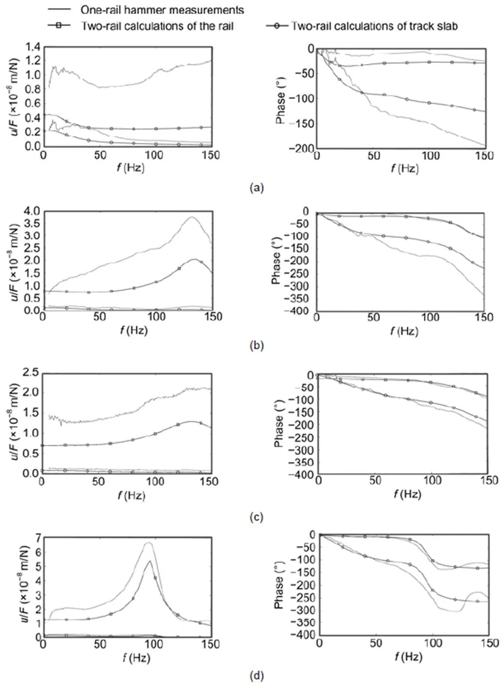
Fig. A1 Transfer functions of slab tracks by one-rail hammer measurements and two-rail calculations of the rail and track slab: (a) site A; (b) site B; (c) site C; (d) site DS1; (e) site DS2; (f) site ES
https://doi.org/10.1631/jzus.A1900651
U213
Dec. 20, 2019;
Apr. 15, 2020;
Jan. 7, 2021
© Zhejiang University Press 2021
 Journal of Zhejiang University-Science A(Applied Physics & Engineering)2021年1期
- Journal of Zhejiang University-Science A(Applied Physics & Engineering)的其它文章
- Vibration response analysis of floating slab track supported by nonlinear quasi-zero-stiffness vibration isolators*
- Formation process, key influencing factors, and countermeasures of high-order polygonal wear of locomotive wheels*
- Environmental noise beside an elevated box girder bridge for urban rail transit*
- Mitigation of high-speed trains vibrations by expanded polystyrene blocks in railway embankments*