
Mitigation of high-speed trains vibrations by expanded polystyrene blocks in railway embankments*
2021-01-13 13:20AlexandrosLYRATZAKISYiannisTSOMPANAKISProdromosPSARROPOULOS
Alexandros LYRATZAKIS, Yiannis TSOMPANAKIS†‡, Prodromos N. PSARROPOULOS
Mitigation of high-speed trains vibrations by expanded polystyrene blocks in railway embankments*
Alexandros LYRATZAKIS1, Yiannis TSOMPANAKIS†‡1, Prodromos N. PSARROPOULOS2
†E-mail: jt@science.tuc.gr
The vibrations induced by the passage of high-speed trains (HSTs) are considered a crucial issue in the field of environmental and geotechnical engineering. Several wave barriers have been investigated to reduce the detrimental effects of HST-induced vibrations. This study is focused on the potential implementation of an innovative mitigation technique to alleviate the developed vibrations. In particular, the use of expanded polystyrene (EPS) blocks as partial fill material of embankment slopes was examined. The efficiency of the proposed mitigation technique was numerically investigated. More specifically, a 3D soil-track model was developed to study the cross-section of a railway track, embankment, and the underlying soil layers. The passage of the HST, Thalys, was simulated using a moving load method, and the soil response was calculated at several distances from the track. Several parameters influenced the effectiveness of the examined mitigation measure. Therefore, to ensure an optimal design, a robust procedure is necessary which considers the impact of these factors. Hence, the implementation of EPS blocks on several embankments with different geometry, in terms of height and slope angle, was investigated.
High-speed railways (HSRs); High-speed trains (HSTs); Traffic-induced vibrations; Mitigation measures; Expanded polystyrene (EPS)
1 Introduction
The major disadvantage of conventional means of transportation, such as cars or busses, is traffic congestion. That issue led to the investigation of alternative solutions for speed and comfort, as well as environmentally friendly transportation. One of the best solutions to this problem is transportation via high-speed trains (HSTs). However, with the progress of train technology and the increasing speed of HSTs, traffic-induced vibrations are considered the most important factor affecting the safety of railway infrastructure and the disturbance of residents living nearby. Hence, researchers have proposed various mitigation measures to minimize the developed vibrations (Takemiya, 2004; Coulier et al., 2015). Generally, these mitigation approaches can be grouped into four categories: (a) track modification, (b) track maintenance (Ferreira and López-Pita, 2015), (c) retrofitting to reduce vibrations of nearby infrastructure (Yang et al., 2019), and (d) installation of wave barriers (Takemiya, 2004; Garinei et al., 2014; Yarmohammadi et al., 2018).
In new railway lines with appropriate route design, optimal locations are selected for track parts such as switches, turnouts, and crossovers, where the vibration level is usually high. In addition, the continuous maintenance of train wheels and rails alleviates traffic-induced vibrations. Apart from railway maintenance and modifications, the retrofitting of nearby buildings and high-speed railway (HSR) infrastructure has been proposed. Moliner et al. (2012) proposed the use of viscoelastic dampers (VEDs) to protect existing railway bridges from HST-induced vibrations. In addition, the use of trenches close to nearby buildings has been proposed to protect them from ground-borne vibrations (Adam and von Estorff, 2005).
The main focus has been the investigation of mitigation measures as a part of the HSR infrastructure, close to the track in the vibration transmission path. The most popular approach to alleviating vibrations induced by HSTs has been the implementation of wave barriers across the railway (With et al., 2009; Yarmohammadi et al., 2019). Open trenches are the most effective type of wave barrier, although several practical issues related to soil stability and the infiltration of surface water have led to the application of in-filled trenches (Yang et al., 2018; Yao et al., 2019).
Through the years, several fill materials have been proposed, such as clay mud, concrete (Al- Hussaini and Ahmad, 1996), gas-filled cushions (Massarsch, 2005) or a sand-rubber mixture (Chew and Leong, 2019). François et al. (2012) investigated the efficiency of a sandwich in-filled trench, using polystyrene as core material and concrete side panels. They concluded that this method was less effective than an open trench. Kanda et al. (2006) studied the impact of a gas cushion trench on vibration mitigation. According to this study, the gas cushion was as effective as open trenches for low frequency range vibrations. Yao et al. (2019) investigated the reflection at the interface between the soil material and the trench fill material and concluded that a higher difference between the properties (i.e. Young’s modulus and density) of the soil and fill material led to a greater reduction of traffic vibrations. Furthermore, several authors have investigated the impact of the width and depth of a trench on the mitigation of vibrations (Beskos et al., 1986; Sitharam et al., 2018).
Apart from open and in-filled trenches, several other wave barriers have been proposed. For instance, the placement of a heavy mass such as a gabion wall across the track was proposed by Dijckmans et al. (2015). Furthermore, wave impeding blocks (WIBs) have been used to reduce the developed vibrations (Gao et al., 2015). WIBs are placed under the track parts and their effectiveness depends on the position and the material properties of the blocks (Çelebi and Göktepe, 2012).
Recently, Lyratzakis et al. (2020) proposed the use of expanded polystyrene (EPS) blocks as an alternative railway embankment side-fill material for the minimization of HST-induced vibrations. According to this technique, a small number of EPS blocks are placed on the embankment’s slope. The use of several types of EPS material was investigated and it was concluded that the use of a stiffer EPS material, such as EPS46, leads to a higher reduction of the vibrations. In this study, the efficiency of this new mitigation scheme was investigated for various embankment geometries. More specifically, the soil response was numerically studied for various embankment heights and slope inclinations, with and without the proposed mitigation measure.
2 Numerical analyses
Highly accurate numerical approaches are necessary for the prediction of traffic-induced vibrations. These incur a high computational cost. Several methods have been proposed in the literature, e.g. finite element method (FEM) (Li et al., 2018), boundary element method (BEM) (Li et al., 2020), or hybrid BEM/FEM formulations (Jin et al., 2018). The simulation of HST dynamic loading is often performed in a computationally cost-efficient manner using a moving load approach, which was used in this study. An efficient multibody approach, the so-called coupled lumped mass (CLM) model, has also been applied in this field, which more realistically takes into account the various complexities related to HST dynamic movement, as well as train and track modeling (Kouroussis, 2019). This approach has been validated in various ballast and soil conditions and is capable of accurately predicting HST-induced vibrations (Kouroussis et al., 2011; Kouroussis and Verlinden, 2015; Olivier et al., 2016). A comparative study revealed that although the CLM model is more accurate, the moving load approach can achieve a satisfactory balance between computation accuracy and efficiency, and that in certain cases the moving load model is also capable of providing reliable results (Feng et al., 2017).
In the current study, a dynamic (explicit time- domain), 3D finite element (FE) model of an HST track/subsoil system was developed. The examined soil profile and embankment of the Thalys HST line connecting Paris with Brussels were taken from a site north-east of Braffe, Belgium (Connolly et al., 2014). The finite/infinite mesh generated using ABAQUS (Dassault Systèmes SIMULIA Corp., 2014) software is illustrated in Fig. 1. Symmetry was used along the track center axis to reduce the computational cost. The finite part of the model was cubic with a depth of 15.5 m and a width of 50 m. The length of the finite part was 50 m, which has been found to be acceptable to achieve convergence to a steady state. The nodes at the bottom boundary were fixed in every direction, aiming to simulate the bedrock.
The guidelines of the International Union of Railways (ISO, 1997) were used to simulate the geometrical and mechanical properties of the track parts. Also, the examined classical ballast track is commonly used on the railway track between Brussels and Paris. Continuously welded UIC-60 section was used for the rails, with a mass per unit length of 60 kg/m. The rails were fixed to concrete monoblock sleepers 2.5 m long, 0.385 m wide, and 0.205 m high. Furthermore, the sleepers were placed at a spacing of 60 cm. The model simulated the ballasted track as shown in Fig. 2; hence, the sleepers were supported by a 0.3 m-high porphyry ballast layer, a 0.2 m-high limestone or porphyry subballast layer, and a 0.5 m-high limestone supporting subgrade layer. The mechanical properties ofthe examined track are summarized in Table 1. To ensure the accuracy of the numerical results, the FE domain should be properly discretized. Generally, the FE size should be small enough to capture the propagation of the vibrations in the examined frequency range, and can be estimated from the smallest wave length,, as follows (Galavi and Brinkgreve, 2014):

where c is the velocity of waves in the examined medium and fmax is the highest frequency of interest.
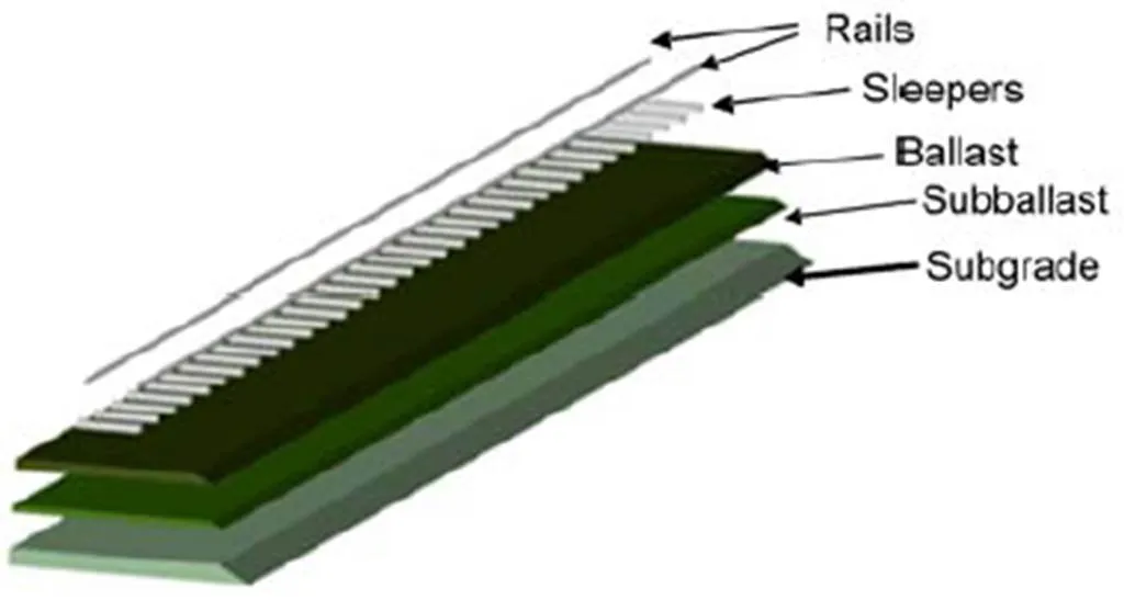
Fig. 2 Geometry of the track parts
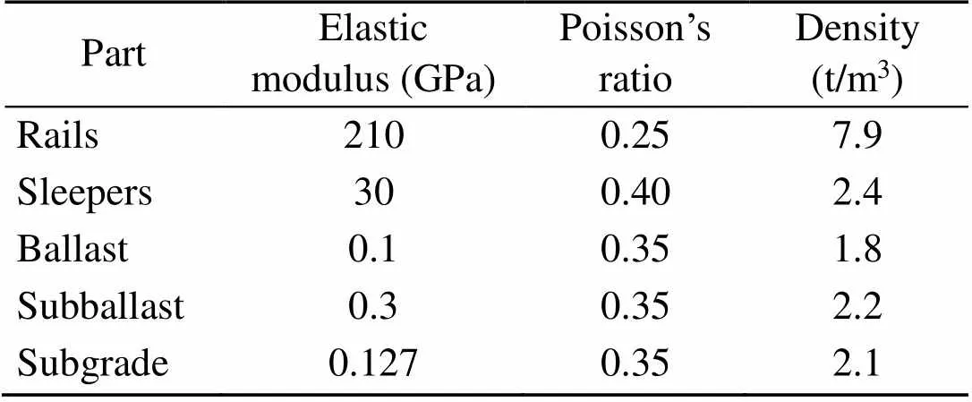
Table 1 Material properties of the track parts
For the modelling of all track components except the rail, 8-noded 0.2 m-long cuboidal FEs along each axis were used, which were capable of capturing the propagation of ground-borne vibrations within the examined frequency range (0–40 Hz). The rails were simulated with 0.1 m-long Euler-Bernoulli beam elements. Hence, the mesh of the FE model for the examined Thalys embankment in Fig. 1 consisted of about 4630000 nodes and 3541000 elements.
The impact of embankment’s geometry on the vibration levels was investigated. For this purpose, several embankments between 3.5 and 5.5 m high and with a slope inclination between 20° and 45°were assessed. Furthermore, the induced vibrations were mitigated with EPS46 blocks, to investigate the efficiency of this mitigation measure with respect to the embankment’s geometry. EPS46 is a low-density material (45.7 kg/m3) with a high elastic modulus (12 800 kPa) and low Poisson’s ratio (0.05). Material damping was taken as 2% (Lyratzakis et al., 2020). A typical soil profile of the Paris-Brussels railway line was used in the present study to investigate the induced vibrations. Table 2 summarizes the material properties of the five soil layers. The total depth of the layers was 9.5 m and the material properties were modelled according to Connolly et al. (2014). The embankment and components of the soil layers were modelled with 0.2 m-long cuboid FEs.
Fig. 3 depicts a schematic diagram of Thalys HST operating on the Paris-Brussels line (Kouroussis and Verlinden, 2013). In its complete configuration it consists of 10 cars, two Y230A locomotives, eight passenger bogies, two Y237A side carriages, and six Y237B central carriages, giving a total length of 200.28 m. Thalys train exerts 26 axle forces (f,=1, 2, …, 26) along the rail. For modeling purposes, a Fortran Vdload subroutine was developed. Furthermore, the numerical stability of the model was ensured by using a small timestep (1.3×10⁻⁶s). A train crossed the embankment at a constant speed of 284 km/h and the moving loads were simplified as a series of constant point forces. Table 3 shows the carriage length (c), the distance between the bogies (b), and the axle distance (a). According to colleagues who collected the field data, one week before the measurements, the rail profilewas maintained and rail unevenness was removed (Connolly et al, 2014; Kouroussis et al, 2016). For this reason, a rational assumption was made that the track had no geometric irregularities and the dynamic response of the soil was investigated for a uniform track geometry.
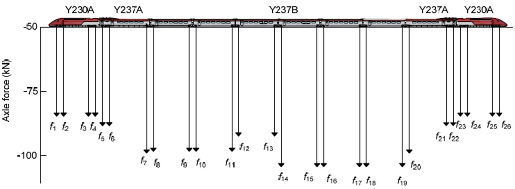
Fig. 3 Thalys HST’s static axle forces (modified from Kouroussis and Verlinden (2013))
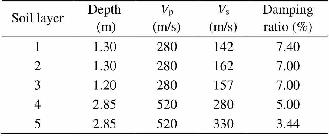
Table 2 Material properties of the soil layers
p: P wave velocity;s: S wave velocity
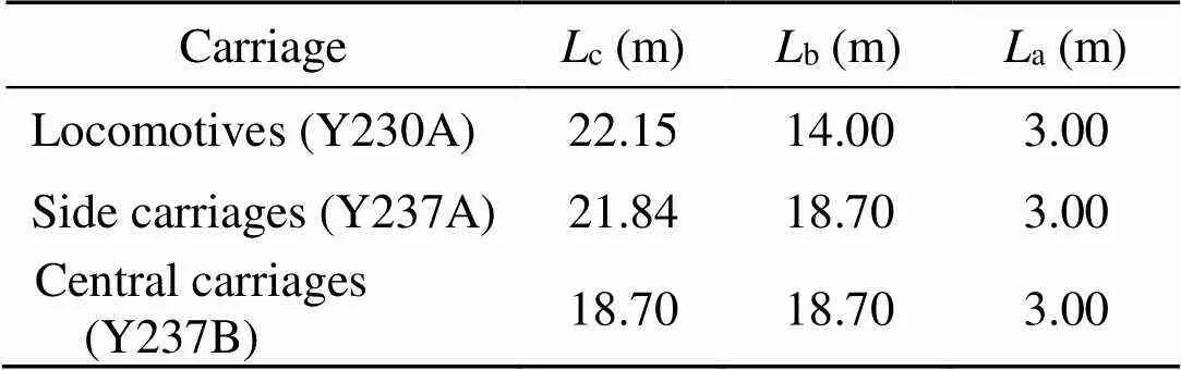
Table 3 Geometrical properties of Thalys HST carriages
To verify the accuracy of the moving load numerical model, the soil’s response during the passage of the Thalys HST was compared with field data from the Paris-Brussels HSR at the selected site (Lyratzakis et al., 2020). The reference FE model which was used for the validation is a soil embankment with a height of 5.5 m and a slope inclination of 30°. More specifically, to ensure the model’s accuracy, the time- histories and Fourier spectra of the vertical velocities at several distances from the track between 15 and 35 m were validated. Detailed results from the model’s validation were recently presented by the authors (Lyratzakis et al., 2020). Note that the numerical prediction of the FE model was in good agreement with the field data, especially in the low frequency range (0–40 Hz). The overall agreement between the numerical results and reference field measurements confirmed that the adopted modelling approach is reliable and can be used with confidence to investigate traffic-induced vibrations due to HST passage for different geometries, soil conditions, train speeds, and mitigation schemes.
3 Numerical results
3.1 Impact of embankment height
To examine the effect of the embankment height on the efficiency of the examined mitigation measure, five embankment cross-sections were examined and compared. All the embankments had a slope angle of 30° and their height varied between 3.5 and 5.5 m (Fig. 4a). The five investigated embankment configurations were constructed from the same soil as the first layer of the underling soil (Table 2). Subsequently, the embankments were mitigated with the placement of EPS46 blocks at their slopes (Fig. 4b). Each EPS block was 1.0 m wide and 1.0 m high. The total number of EPS blocks implemented in each case was 2, whereis the height of the embankment.
For each embankment, the far-field vibrations at various locations from the track/embankment structure were studied to determine the potential damage to structures and infrastructure in close proximity to the railway, and the level of mitigation of the vibrations achieved due to the implementation of EPS blocks.
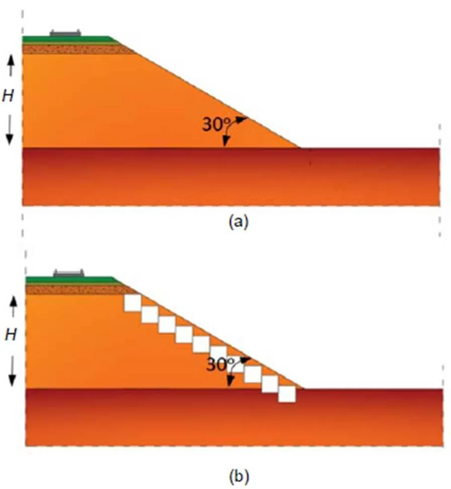
Fig. 4 Cross-section of the soil embankment (a) and the embankment mitigated with EPS46 blocks (b) for constant slope inclination and varying height
Fig. 5 illustrates the Fourier spectra for the first observation point located 15 m from the track. In the case of the soil embankment, the impact of its height on the vibrations induced by the Thalys HST’s passage was marginal. However, in the case of the embankment mitigated with EPS46, it can be observedthat the effect of its height was more important. This mitigation measure was more effective for higher embankments. For instance, in the case of the highest embankment, with a height of 5.5 m, the effect of the EPS blocks was more significant, as the vibrations’ peaks in the range from 10 to 28 Hz were successfully mitigated. More specifically, the main frequencies at 21.4 and 25.2 Hz which can be close to the most important frequencies of the nearby buildings and infrastructure were successfully attenuated. In the case of higher frequencies, the vibration remained atthe same level. Furthermore, the peaks at several frequencies between 10 and 28 Hz were successfully reduced with the use of EPS blocks for all the examined embankments. However, the peaks at 29.6 and 34.0 Hz were increased as the embankment height decreased. For the lower height embankments, the peak at 29.6 Hz was significantly increased.
Fig. 6 shows the effect on vibration propagation due to the passage of Thalys HST at a distance of 35 m from the track for both the soil and the EPS-retrofitted embankments. As expected, all the peaks were lower than those of the previously examined point (at 15 m from the track). At 35 m from the track, there were no significant changes in the vibration level in the case of the soil embankment, whereas the implementation of EPS blocks successfully reduced the developed vibrations at that point for all heights. For embankments with heights ranging from4.5 to 5.5 m, the vibration peaks were attenuated by the EPS blocks for the whole low frequency range between 0 and 40 Hz. However, in the case of thelower embankments (<4.5 m), the peaks at 29.6 and 34.0 Hz were slightly increased, although the magnitude of the vibrations was reduced for the rest of the examined frequencies.
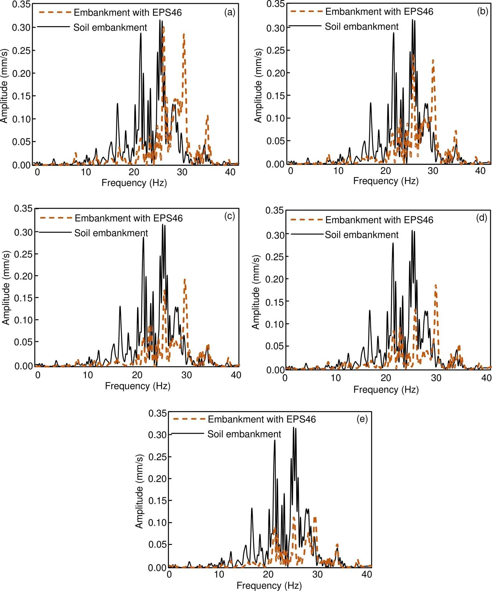
Fig. 5 Comparison of soil and EPS-retrofitted embankments in terms of vertical velocity Fourier spectra at 15m from the track for embankment’s height equal to 3.5m (a), 4.0m (b), 4.5m (c), 5.0m (d), and 5.5m (e)
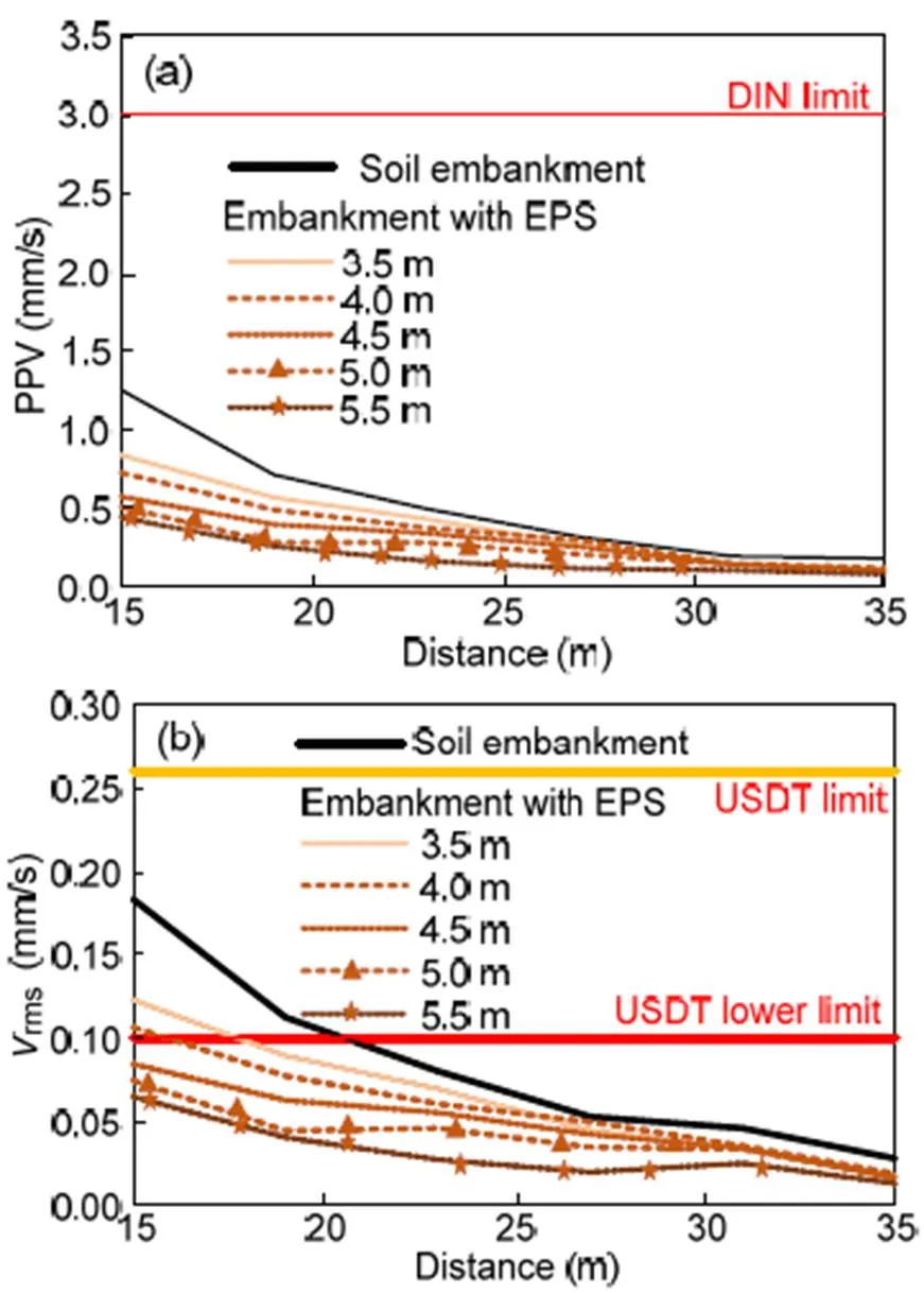
Fig. 7a illustrates the peak partial velocity (PPV) at six equally spaced observation points between 15 and 35 m from the rails of the track/embankment structure. As previously mentioned, the PPV was reduced with distance from the track. Moreover, the PPV was significantly decreased for all the examined embankment heights at all the observation points after the mitigation with a small number of EPS blocks. In particular, the mitigation was more pronounced for the higher embankments. According to the German Institute for Standardization (DIN, 1999b), the PPV limit is 3 mm/s, to protect sensitive buildings from potential damages. Herein, the PPV of all the examined models at distances from 15 to 35 m from the track was significantly lower than this limit. Hence, the construction of sensitive buildings across the track is feasible. Note that the PPV is defined as follows:
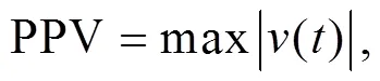
where v(t) is the velocity time-history.
Apart from the potential damages to nearby buildings, the discomfort of the residents from the passage of the HST should be assessed. Several parameters have been proposed to estimate the level of the residents’ disturbance (e.g. DIN (1999a), ISO (2003)). According to the United States Department of Transportation (USDT, 1998), the highest value of the root means square amplitude of the velocity time- history (rms) to avoid discomfort of the residents is 0.10 mm/s for infrequent passages of HST (<70 passages per day). This value is increased to 0.26 mm/s for more than 70 passages per day. In the case of the soil embankment, thermsvalues for distances between 15 and 20 m were clearly higher than the USDT lower limit (Fig. 7b). The implementation of the EPS blocks contributed to the reduction of these high values. Especially for embankments with heights from 4.5 to 5.5 m, thermsvalues were acceptable for all the examined frequencies.
Furthermore, the USDT proposed a decibel scale to assess the impact of HST-induced vibrations. According to US standards, this decibel scale aims to minimize the required data to describe the traffic induced vibration leveldB, which is calculated by
where0is a reference value that represents the background level of vibrations, which is taken equal to 5×105mm/s (Kouroussis et al., 2014).
The World Health Organization (WHO/Europe, 2018) noted that vibrations above 55 dB are quite dangerous for public health. More specifically, detrimental health effects could be experienced by most of the residents as they become annoyed and sleep-disturbed, increasing the risk of cardiovascular diseases. In the case of the standard soil embankment,dBvalues were higher than 55 dB for all the examined distances. The mitigation with EPS blocks did not reduce those values significantly, except for the case of the highest embankment (5.5 m), where the vibration level was lower than 55 dB for distances between 22 and 35 m from the track (Fig.7c).
The German Institute for Standardization (DIN, 1999a) proposed the comparison between the maximum level of the weighted time-averaged signal (KBF,max) and the limit of 0.15 mm/s for residential areas. Fig. 7d shows that the KBF,maxvalues in the case of the soil embankment were above 0.15 mm/s for most of the examined cases. The implementation of EPS blocks significantly reduced the level of KBF,maxfor all the examined heights. Note that in the case of the highest embankment (5.5 m), the level of KBF,maxwas lower than 0.15 mm/s when the distance is between 21 and 35 m. KBF,maxcan be derived from:
whereis the examined frequency (herein set equal to 25.2 Hz). It should be mentioned that for frequencies higher than 20 Hz, KBF,maxis not significantly altered.
3.2 Impact of embankment slope inclination
The impact of the inclination of the embankment slope on HST-induced vibrations is described in this section. Several soil embankments with a constant height of 5.5 m and a slope angle () ranging from 20° to 45° were investigated. Similarly, the same soil as the first underlying layer was used as embankment fill material (Fig. 8a) for the initial embankment. Then, EPS blocks were placed at the embankment slope to mitigate the developed vibrations (Fig. 8b). The vibration levels at distances ranging from 15 to 35 m from each embankment were investigated to determine the contribution of the inclination of the embankment slope to the propagation of the vibrations.
Fig. 9 shows the PPV of all the examined cases, and it is obvious that an increase in slope inclination can significantly influence the propagation of the vibrations. As expected, a steeply inclined embankment causes a significant decrease in vibration levels, while embankments with lower inclination showed a corresponding increase. More specifically, at 15 m from the track, the PPV level in the case of the embankment with a slope inclination of 20° was increased by about 120%, in contrast to the embankment with a 45° slope. Hence, the construction of embankments with high inclination leads to a reduction of far field vibrations. On the other hand, the construction of embankments with a low slope inclination should be avoided.
Fig. 10 illustrates a comparison between the soil embankment and the embankment mitigated with EPS46 blocks for three embankment slope inclinations: (a) 20°, (b) 30°, (c) 45°. Similar to the PPV results, an increase of the slope inclination contributed to a reduction of the vibration levels. The two dominant vibration peaks at 21.4 and 25.2 Hz were notably reduced in the case of the higher inclination. The vibration peak at 25.2 Hz was reduced from 0.47 mm/s in the case of 20° inclination, to 0.31 mm/s in the case of 30° inclination. This reduction was even higher in the case of 45° slope, where the vibration peak at 25.2 Hz was equal to 0.25 mm/s.
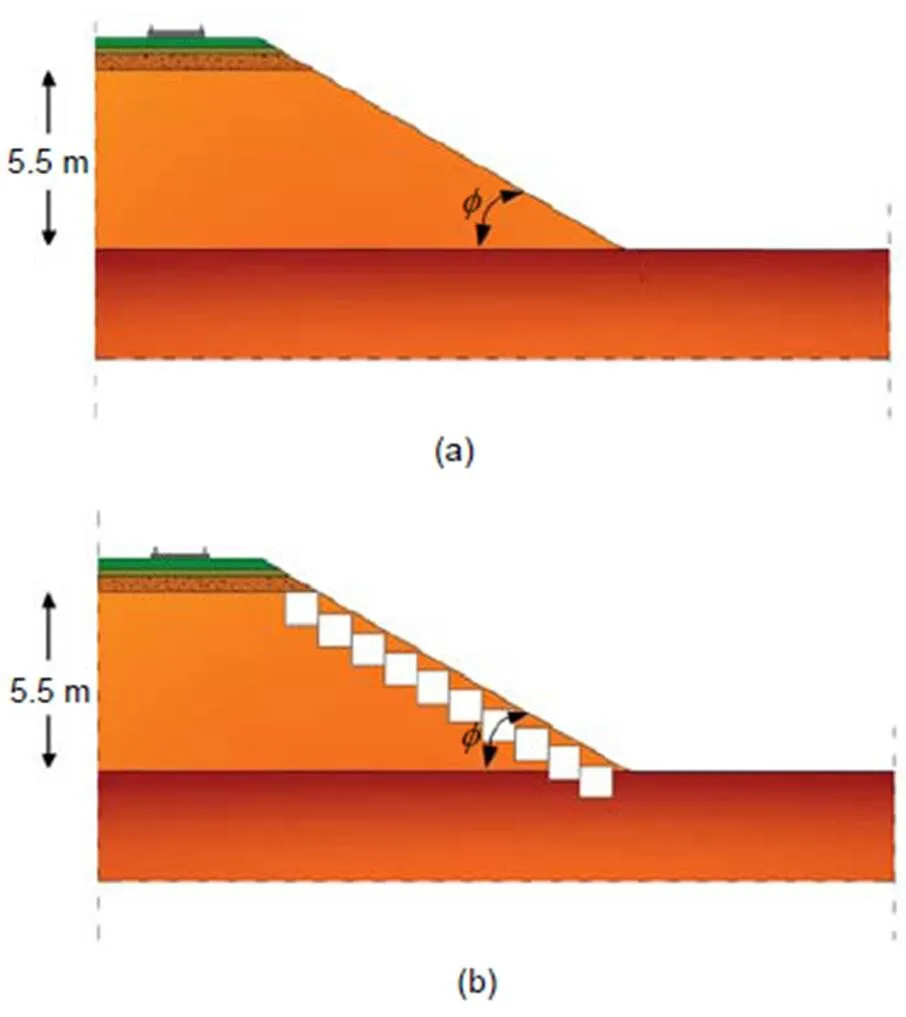
Fig. 8 Cross-section of the soil embankment (a) and the embankment mitigated with EPS46 blocks (b) for varying slope inclinations and constant height
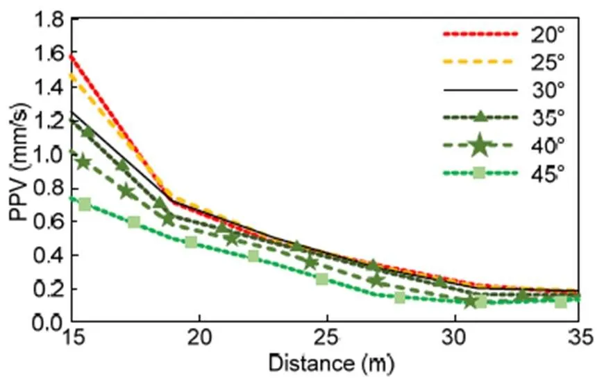
Fig. 9 Comparison of PPV at increasing distance from the track for the 5.5 m soil embankment for various slope inclinations
The efficiency of the examined mitigation system is shown in Fig. 10. In the case of a 20° inclination, the vibration peak at 25.2 Hz almost disappeared. Furthermore, the vibration peaks at 18.1, 21.4, and 28.1 Hz were significantly reduced. The same results were observed for the other two cases. Note that the vibration peaks at 21.4 Hz and 25.2 Hz were significantly reduced by more than 60% (Fig. 10b). This reduction was lower in the case of a 45° inclination (Fig. 10c), where the two dominant vibration peaks were reduced from 0.19 to 0.08 mm/s at 21.4 Hz, and from 0.25 to 0.14 mm/s at 25.2 Hz, respectively.
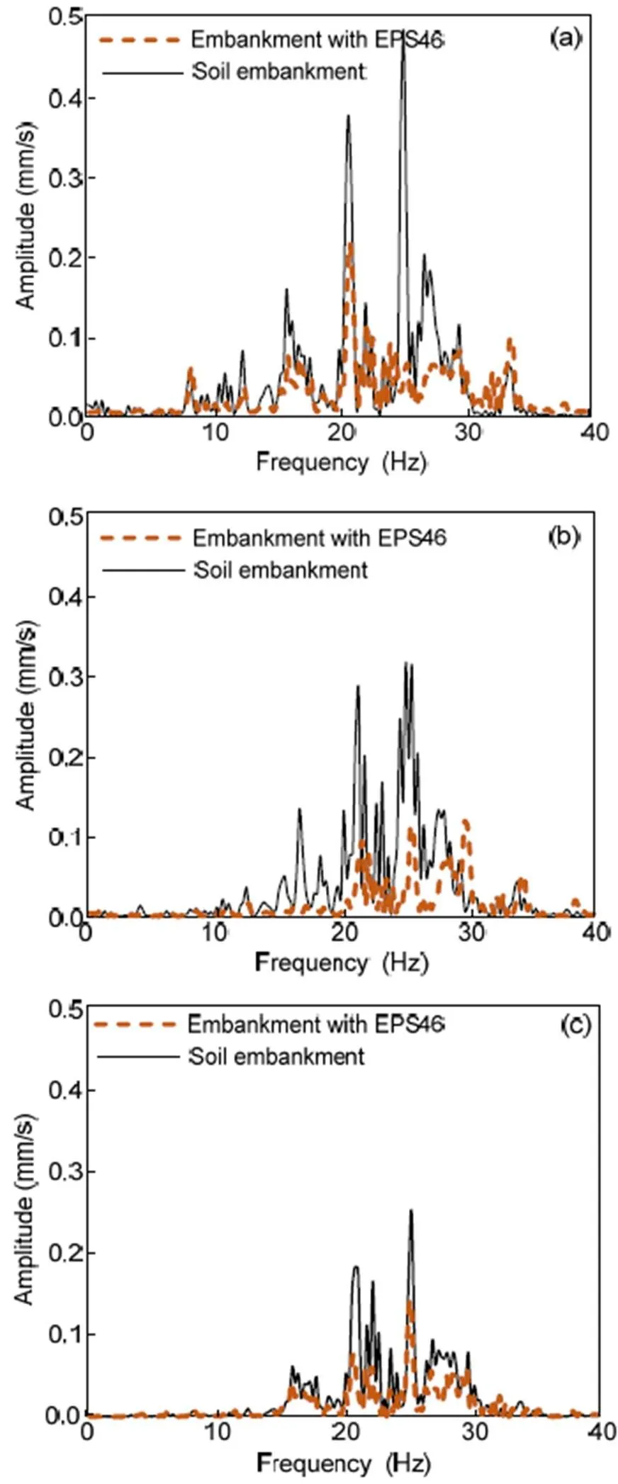
Fig. 10 Comparison of soil and EPS-retrofitted embankments in terms of vertical velocity Fourier spectra at 15 m from the track for embankment slope inclinations of 20° (a), 30° (b), and 45°(c)
The same trend was observed at 35 m from the track (Fig. 11). In the case of the soil embankment, the vibration level was higher for the milder slope. The most dominant peak at 25.2 Hz was 0.12 mm/s for a 20° inclination, in contrast to 0.08 mm/s for a 30°, and 0.04 mm/s for a 45°inclination. The same observation was made for all the peaks at the low frequency range between 0 and 40 Hz. The implementation of EPS blocks on the embankment slope significantly reduced the vibrations induced by the Thalys HST at 35 m from the track. In the modeling scenario of a 20° slope inclination, all the vibration peaks at 18.1, 21.4, 25.2, and 28.1 Hz almost disappeared. Furthermore, in the other two cases (Figs. 11b and 11c) the proposed mitigation technique contributed to a reduction of the vibrations across the whole examined frequency range (0 to 40 Hz).
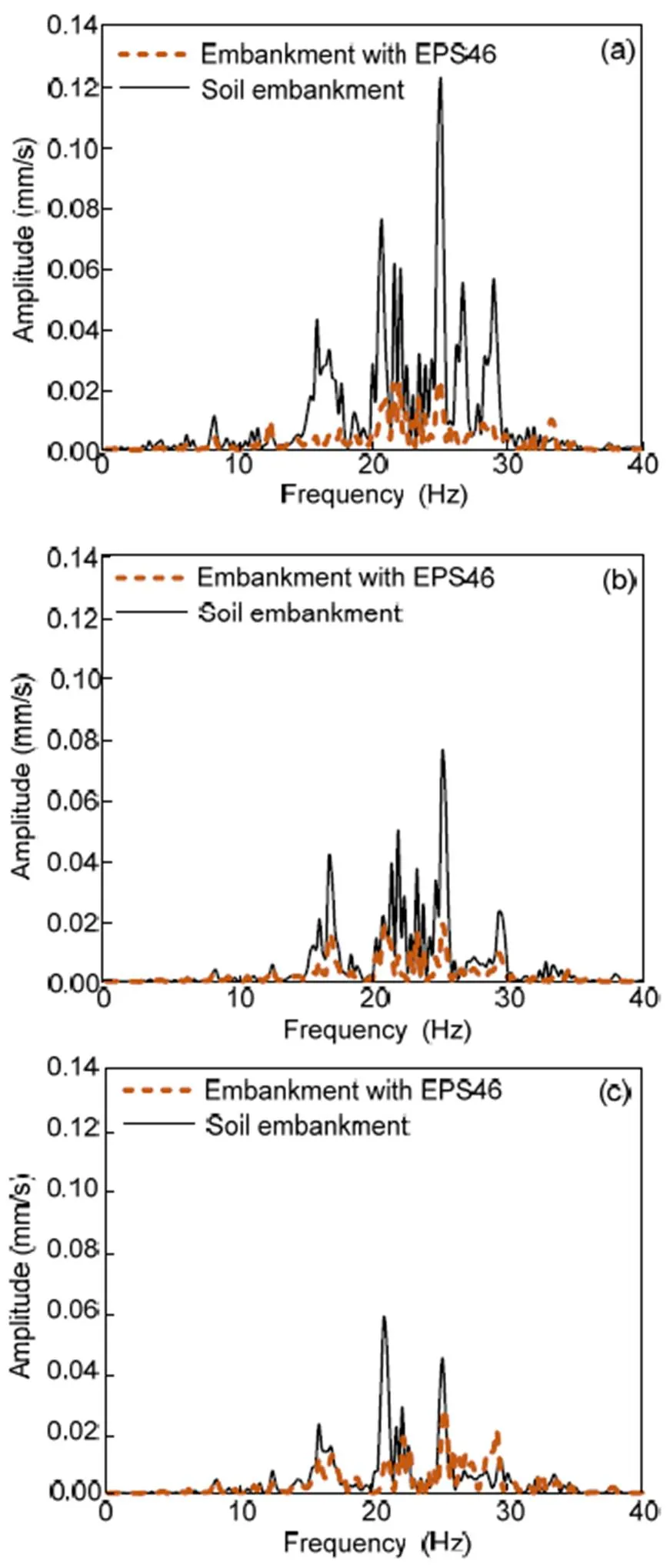
Fig. 11 Comparison of soil and EPS-retrofitted embankments in terms of vertical velocity Fourier spectra at 35 m from the track for embankment slope inclinations of 20° (a), 30° (b), and 45° (c)
Fig. 12 presents the vibration levels in terms of PPV,dB,rms, and KBF,maxat six equally spaced positions, ranging between 15 and 35 m from the track in the case of the embankment with slope inclination 20°. As expected, these values decreased with distance from the embankment. The PPV at all the examined distances from the track did not exceed the DIN limit for potential damage to sensitive nearby buildings (Fig. 12a). Furthermore, thermsof the soil embankment was higher than the lower USDT limit for frequent passages of HSTs at distances between 15 and 21 m from the track. The examined mitigation technique contributed to the decrease of thermsvalue to under 0.10 mm/s for all the examined distances. In addition, thedBlevel was reduced to below 55 dB for distances greater than 28 m from the track after the mitigation with EPS blocks. The same trend was observed for KBF,maxvalues (Fig. 12d). The implementation of EPS blocks reduced the KBF,maxto below the DIN limit for distances between 26 and 35 m from the track.
Fig. 13 illustrates the vibrations propagation at distances from 15 to 35 m from the track in the examined scenario of an embankment with a 30° slope inclination. As previously mentioned, in this case the PPV level was lower than the case of a 20° slope inclination. Hence, the PPV was lower than the DIN threshold, and these values were even lower after the mitigation with EPS blocks. On the other hand, thermsvalues were lower than the USDT lower limit for frequent passages of HSTs at distances greater than 21 m from the track. The installation of EPS blocks on the embankment’s slope contributed to the reduction of thermsto below this limit for all the distances between 15 and 35 m from the track. Fig. 13c shows a comparison of the initial and mitigated embankments at increasing distances from the track in terms ofdB. Note that in the case of the soil embankment, thedBwas higher than the 55 dB threshold for the whole examined range. The implementation of EPS blocks reduced thedBvalues to below the 55 dB limit for distances greater than 23 m. In addition, the DIN limit value for KBF,maxwas not exceeded for distances greater than 21 m after the mitigation with EPS blocks.
Fig. 14 presents the vibrations level in terms of PPV,dB,rms, and KBF,maxat increasing distances from the track in the case of an embankment with a 45°slope inclination. In the case of the soil embankment, the PPV andrmsvalues were extremely low. In particular, thermsvalue was lower than the USDT lower limit of 0.10 mm/s and the PPV was lower than the DIN limit of 3 mm/s for almost all the examined distances from the track. Furthermore, the implementation of EPS blocks led to even lower values ofrmsand PPV. ThedBlevel of the soil embankment was under 55 dB for distances greater than 26 m from the track. Furthermore, the mitigation of the embankment with EPS block contributed to a further reduction of the vibration levels. In this case, thedBlevel was lower than 55 dB for remote distances between 23 and 35 m from the track (Fig. 14c). The same trend was observed for KBF,maxvalues, which did not exceed the DIN limit value of 0.15 mm/s for remote distances (i.e. >21 m) from the track.
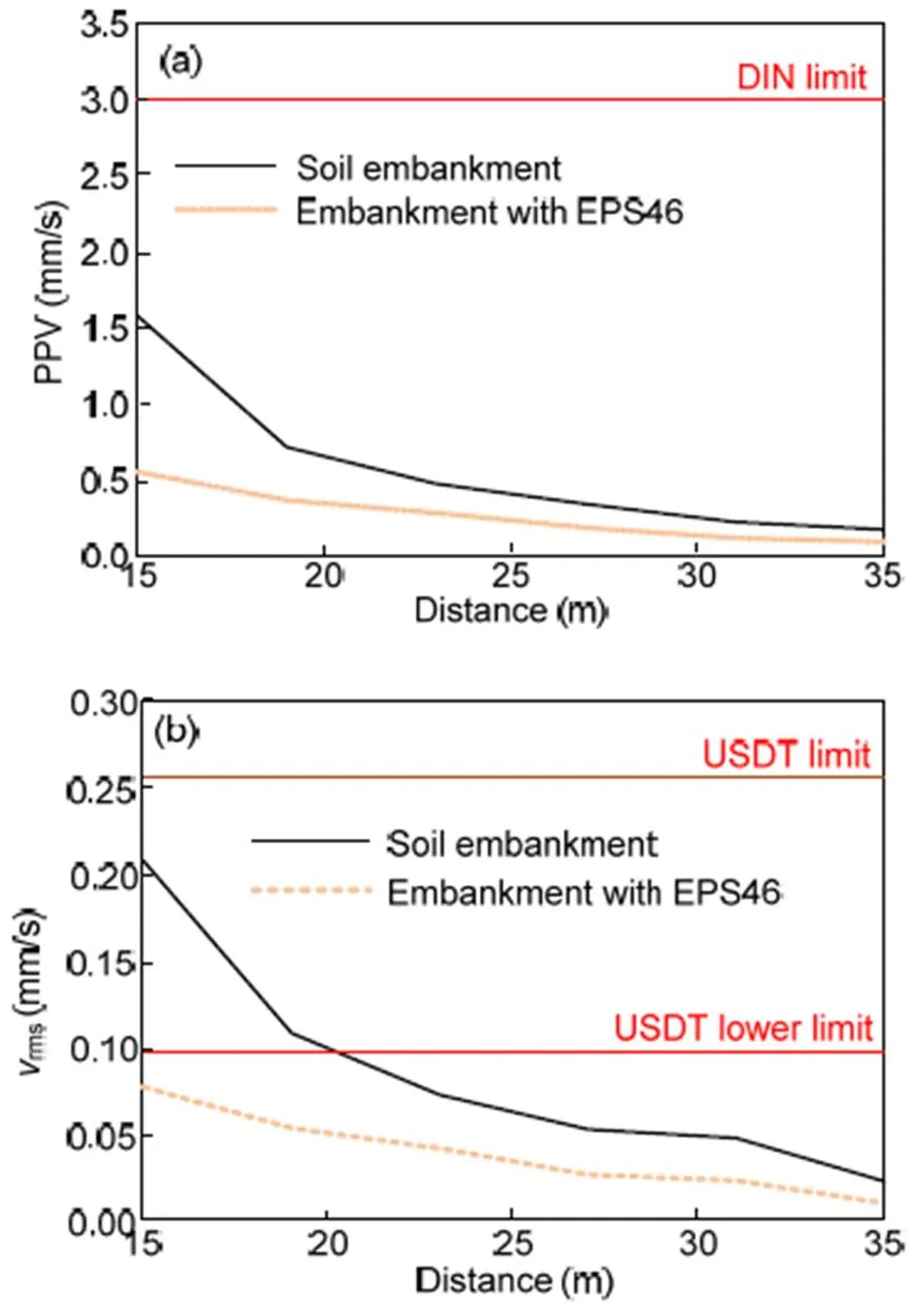
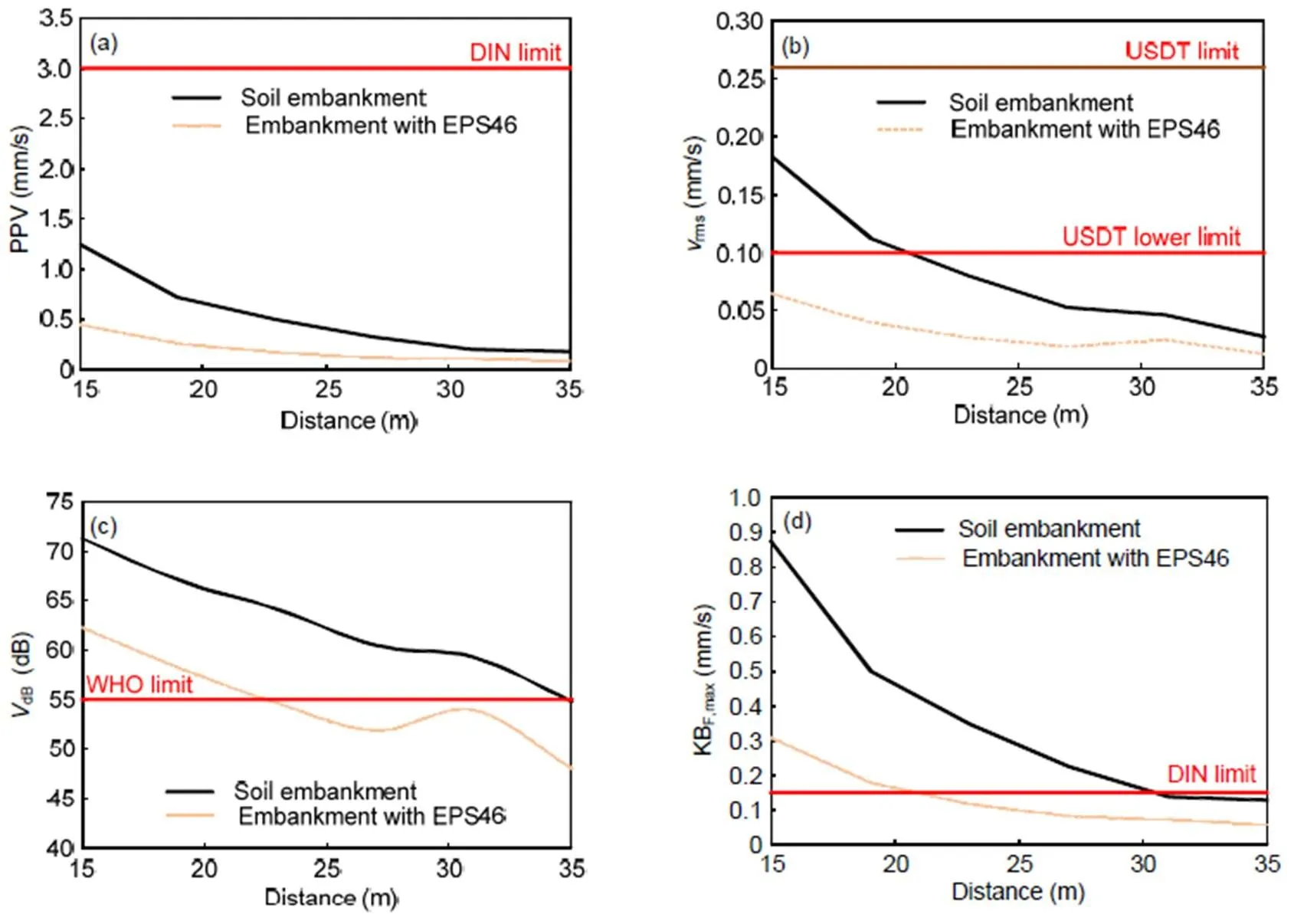
Fig. 13 Comparison of soil and EPS-retrofitted embankments with a slope inclination of 30° at increasing distance from the track in terms of PPV (a), vrms (b), VdB (c), and KBF,max (d)
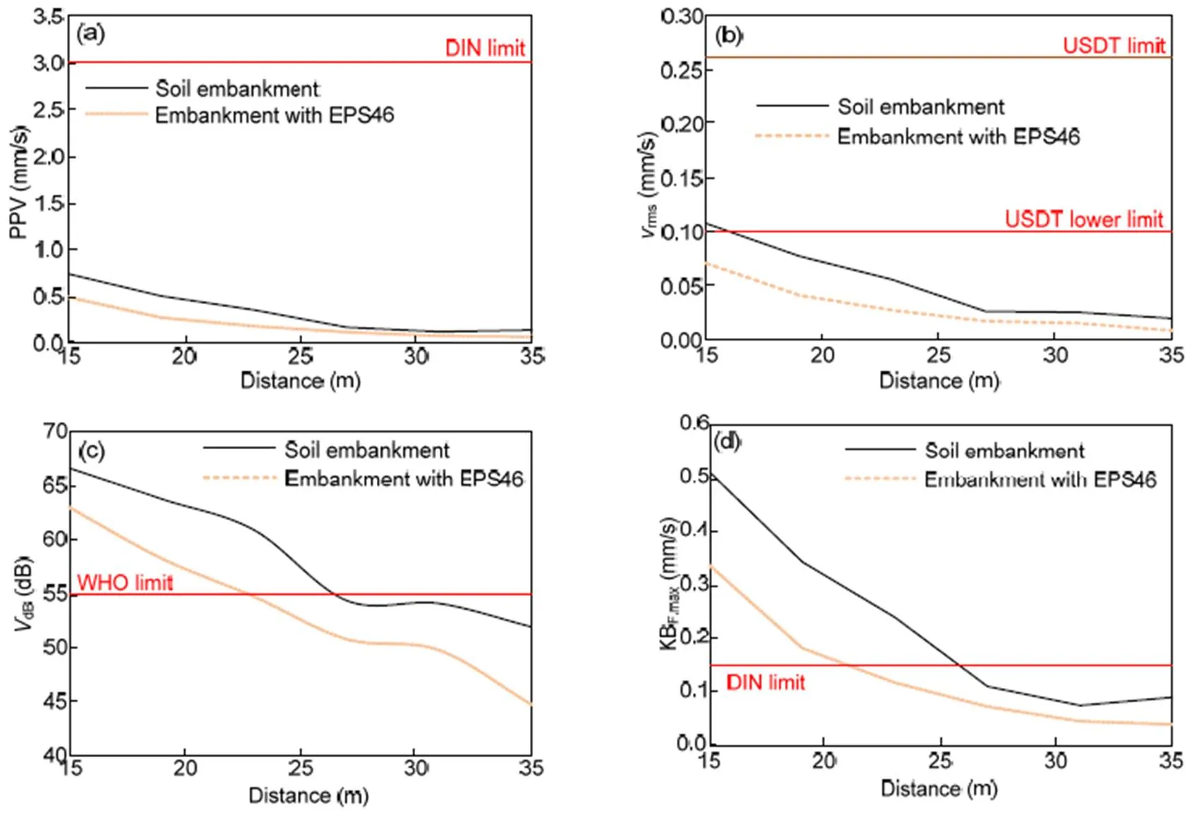
Fig. 14 Comparison of soil and EPS-retrofitted embankments with a slope inclination of 45° at increasing distance from the track in terms of PPV (a), vrms (b), VdB (c), and KBF,max (d)
5 Conclusions
In this study, the impact of embankment height and slope inclination on the propagation of traffic- induced vibrations by the passage of Thalys HST was investigated. For this purpose, a reliable 3D FE numerical model in conjunction with the method of moving loads was developed. According to the results of this parametric study, the impact of embankment geometry should be considered when mitigating ground-borne vibrations due to HST passage.
The main conclusions that can be drawn from the presented numerical investigation are as follows:
The soil embankment height has a rather marginal impact on the propagation of the vibrations when the slope inclination is constant and the embankment fill material is the same as the upper subgrade layer. The implementation of EPS blocks contributed to the mitigation of the induced vibrations for all the examined embankment heights, especially at frequencies close to the fundamental frequencies of the adjacent buildings and infrastructure.
The soil embankment slope inclination plays a more crucial role on the level of the HST-induced vibrations. A steeper slope leads to lower vibration levels. However, the implementation of EPS blocks contributed to the mitigation of the vibrations for all the examined slope inclinations.
PPV values were lower than the DIN limit for protection of nearby buildings from potential damage. Nevertheless, PPV values were reduced after the mitigation with EPS blocks for all the examined locations between 15 and 35 m from the track, while the mitigation technique was more effective for higher embankments.
The mitigation of the embankment with EPS blocks also led to a reduction ofrmsvalues to below the USDT threshold for frequent passages of HSTs. The vibration levels in terms ofdBand KBF,maxwere also reduced.
Finally, note that the analyses presented in this study did not take into account possible track irregularities. Hence, further investigation is required to assess the efficiency of the proposed mitigation technique using a more elaborate numerical model, capable of including the impact of rail unevenness. Moreover, the combination of EPS blocks with other mitigation measures (e.g. trenches) could also be examined to further enhance their efficiency, taking into account cost issues as well.
Contributors
Alexandros LYRATZAKIS: conceptualization, investigation, methodology, software, validation, writing–original draft. Yiannis TSOMPANAKIS: project administration, supervision, conceptualization, investigation, methodology, writing–review and editing. Prodromos N. PSARROPOULOS: conceptualization, investigation, methodology, writing –review and editing.
Conflict of interest
Alexandros LYRATZAKIS, Yiannis TSOMPANAKIS, and Prodromos N. PSARROPOULOS declare that they have no known competing financial interests or personal relationships that could have appeared to influence the work reported in this paper.
Adam M, von Estorff O, 2005. Reduction of train-induced building vibrations by using open and filled trenches., 83(1):11-24. https://doi.org/10.1016/j.compstruc.2004.08.010
Al-Hussaini TM, Ahmad S, 1996. Active isolation of machine foundations by in-filled trench barriers., 122(4):288-294. https://doi.org/10.1061/(asce)0733-9410(1996)122:4(288)
Beskos DE, Dasgupta B, Vardoulakis IG, 1986. Vibration isolation using open or filled trenches. Part 1: 2-D homogeneous soil., 1(1):43-63. https://doi.org/10.1007/BF00298637
Çelebi E, Göktepe F, 2012. Non-linear 2-D FE analysis for the assessment of isolation performance of wave impeding barrier in reduction of railway-induced surface waves., 36:1-13. https://doi.org/10.1016/j.conbuildmat.2012.04.054
Chew JH, Leong EC, 2019. Field and numerical modelling of sand-rubber mixtures vibration barrier., 125:105740. https://doi.org/10.1016/j.soildyn.2019.105740
Connolly DP, Kouroussis G, Woodward PK, et al., 2014. Field testing and analysis of high speed rail vibrations., 67:102-118. https://doi.org/10.1016/j.soildyn.2014.08.013
Coulier P, Cuéllar V, Degrande G, et al., 2015. Experimental and numerical evaluation of the effectiveness of a stiff wave barrier in the soil., 77:238-253. https://doi.org/10.1016/j.soildyn.2015.04.007
Dassault Systèmes SIMULIA Corp., 2014. ABAQUS Analysis User’s Manual Version 6.14. Dassault Systèmes SIMULIA Corp., Providence, RI, USA.
Dijckmans A, Coulier P, Jiang J, et al., 2015. Mitigation of railway induced ground vibration by heavy masses next to the track., 75:158-170. https://doi.org/10.1016/j.soildyn.2015.04.003
DIN (Deutsches Institut für Normung), 1999a. Structural Vibrations–Part 2: Human Exposure to Vibration in Buildings, DIN 4150-2:1999. National Standards of Germany (in German).
DIN (Deutsches Institut für Normung), 1999b. Structural Vibrations–Part 3: Effects of Vibration on Structures, DIN 4150-3:1999. National Standards of Germany (in German).
Feng SJ, Zhang XL, Zheng QT, et al., 2017. Simulation and mitigation analysis of ground vibrations induced by high-speed train with three dimensional FEM., 94:204-214. https://doi.org/10.1016/j.soildyn.2017.01.022
Ferreira PA, López-Pita A, 2015. Numerical modelling of high speed train/track system for the reduction of vibration levels and maintenance needs of railway tracks., 79:14-21. https://doi.org/10.1016/j.conbuildmat.2014.12.124
François S, Schevenels M, Thyssen B, et al., 2012. Design and efficiency of a composite vibration isolating screen in soil., 39: 113-127. https://doi.org/10.1016/j.soildyn.2012.03.007
Galavi V, Brinkgreve RBJ, 2014. Finite element modelling of geotechnical structures subjected to moving loads. Proceedings of the 8th European Conference on Numerical Methods in Geotechnical Engineering.
Gao GY, Li N, Gu XQ, 2015. Field experiment and numerical study on active vibration isolation by horizontal blocks in layered ground under vertical loading., 69:251-261. https://doi.org/10.1016/j.soildyn.2014.11.006
Garinei A, Risitano G, Scappaticci L, 2014. Experimental evaluation of the efficiency of trenches for the mitigation of train-induced vibrations., 32:303-315. https://doi.org/10.1016/j.trd.2014.08.016
ISO (International Organization for Standardization), 1997. Mechanical Vibration and Shock–Evaluation of Human Exposure to Whole-body Vibration–Part 1: General Requirements, ISO 2631-1:1997. International Organization for Standardization, Geneva, Switzerland.
ISO (International Organization for Standardization), 2003. Mechanical Vibration and Shock–Evaluation of Human Exposure to Whole-body Vibration–Part 2: Vibration in Buildings (1 Hz to 80 Hz), ISO 2631-2:2003. International Organization for Standardization, Geneva, Switzerland.
Jin QY, Thompson DJ, Lurcock DEJ, et al., 2018. A 2.5D finite element and boundary element model for the ground vibration from trains in tunnels and validation using measurement data, 422: 373-389. https://doi.org/10.1016/j.jsv.2018.02.019
Kanda H, Ishii H, Yoshioka O, 2006. Use of gas cushions for field measurement and analysis of hybrid vibration isolation wall., 1983(1):42-50. https://doi.org/10.1177/0361198106198300107
Kouroussis G, 2019. Predicting high-speed railway vibration using time-domain numerical engineering approaches.: Krylov VV (Ed.), Ground Vibrations from High-speed Railways. ICE Publishing, London, UK, p.187-216. https://doi.org/10.1680/gvfhsr.63792.187
Kouroussis G, Verlinden O, 2013. Prediction of railway induced ground vibration through multibody and finite element modelling., 4(1):167-183. https://doi.org/10.5194/ms-4-167-2013
Kouroussis G, Verlinden O, 2015. Prediction of railway ground vibrations: accuracy of a coupled lumped mass model for representing the track/soil interaction, 69:220-226. https://doi.org/10.1016/j.soildyn.2014.11.007
Kouroussis G, Gazetas G, Anastasopoulos I, et al., 2011. Discrete modelling of vertical track–soil coupling for vehicle –track dynamics., 31(12):1711-1723. https://doi.org/10.1016/j.soildyn.2011.07.007
Kouroussis G, Conti C, Verlinden O, 2014. Building vibrations induced by human activities: a benchmark of existing standards., 15(5):345-353. https://doi.org/10.1051/meca/2014041
Kouroussis G, Connolly DP, Olivier B, et al., 2016. Railway cuttings and embankments: experimental and numerical studies of ground vibration.,557-558:110-122. https://doi.org/10.1016/j.scitotenv.2016.03.016
Li L, Nimbalkar S, Zhong R, 2018. Finite element model of ballasted railway with infinite boundaries considering effects of moving train loads and Rayleigh waves., 114:147-153. https://doi.org/10.1016/j.soildyn.2018.06.033
Li QT, Duhamel D, Luo YY, et al., 2020. Analysing the acoustic performance of a nearly-enclosed noise barrier using scale model experiments and a 2.5-D BEM approach., 158:107079. https://doi.org/10.1016/j.apacoust.2019.107079
Lyratzakis A, Tsompanakis Y, Psarropoulos PN, 2020. Efficient mitigation of high-speed trains induced vibrations of railway embankments using expanded polystyrene blocks., 22:100312https://doi.org/10.1016/j.trgeo.2019.100312
Massarsch KR, 2005. Vibration isolation using gas-filled cushions.: Stoke II KH, Anderson D, Rathje EM (Eds.), Soil Dynamics Symposium in Honor of Professor Richard D. Woods. ASCE, Austin, USA. https://doi.org/10.1061/40780(159)7
Moliner E, Museros P, Martínez-Rodrigo MD, 2012. Retrofit of existing railway bridges of short to medium spans for high-speed traffic using viscoelastic dampers., 40:519-528. https://doi.org/10.1016/j.engstruct.2012.03.016
Olivier B, Connolly DP, Costa PA, 2016. The effect of embankment on high speed rail ground vibrations., 4(4):229-246. https://doi.org/10.1080/23248378.2016.1220844
Sitharam TG, Sebastian R, Fazil F, 2018. Vibration isolation of buildings housed with sensitive equipment using open trenches–case study and numerical simulations., 115:344-351. https://doi.org/10.1016/j.soildyn.2018.08.033
Takemiya H, 2004. Field vibration mitigation by honeycomb WIB for pile foundations of a high-speed train viaduct., 24(1):69-87. https://doi.org/10.1016/j.soildyn.2003.07.005
USDT (United States Department of Transportation), 1998. High-speed Ground Transportation. Noise and Vibration Impact Assessment. Technical Report 293630-1, United States Department of Transportation, Federal Railroad Administration, Washington, USA.
WHO/Europe (World Health Organization/Regional Office for Europe), 2018. Environmental Noise Guidelines for the European Region. WHO Regional Office for Europe, Copenhagen, Denmark.
With C, Bahrekazemi M, Bodare A, 2009. Wave barrier of lime–cement columns against train-induced ground- borne vibrations., 29(6):1027-1033. https://doi.org/10.1016/j.soildyn.2008.12.005
Yang JJ, Zhu SY, Zhai WM, et al., 2019. Prediction and mitigation of train-induced vibrations of large-scale building constructed on subway tunnel., 668:485-499. https://doi.org/10.1016/j.scitotenv.2019.02.397
Yang YB, Ge PB, Li QM, et al., 2018. 2.5D vibration of railway-side buildings mitigated by open or infilled trenches considering rail irregularity., 106:204-214. https://doi.org/10.1016/j.soildyn.2017.12.027
Yao JB, Zhao RT, Zhang N, et al., 2019. Vibration isolation effect study of in-filled trench barriers to train-induced environmental vibrations., 125:105741. https://doi.org/10.1016/j.soildyn.2019.105741
Yarmohammadi F, Rafiee-Dehkharghani R, Behnia C, et al., 2018. Topology optimization of jet-grouted overlapping columns for mitigation of train-induced ground vibrations., 190:838-850. https://doi.org/10.1016/j.conbuildmat.2018.09.156
Yarmohammadi F, Rafiee-Dehkharghani R, Behnia C, et al., 2019. Design of wave barriers for mitigation of train–induced vibrations using a coupled genetic-algorithm/finite-element methodology., 121:262-275. https://doi.org/10.1016/j.soildyn.2019.03.007
题目:轨道路堤铺设聚苯乙烯泡沫块对高速铁路车致振动的减振效果研究
目的:高速列车运行引起的振动问题在环境工程和地质工程中被视为重要的研究课题。为了减小高速列车运行引起的不利振动,本文聚焦于一种创新减振技术的潜在应用,并通过数值计算分析聚苯乙烯泡沫块铺设在不同几何参数的轨道路堤上时对车致振动的减振效果,从而实现减振方案的最优设计。
创新点:1. 探明了不同路堤高度和不同路堤斜坡倾角对车致振动规律的影响。2. 分析一种聚苯乙烯泡沫块在高速铁路车致振动中的减振效果。
方法:1. 建立三维的轨道-路堤-土体有限元模型,结合移动载荷法分析高速列车运行引起的地面振动。2. 通过参数化研究分析轨道路堤高度和斜坡倾角对于振动波传递的影响。3. 分析聚苯乙烯泡沫块使用前后高速列车运行引起的地面振动。
结论:1. 轨道路堤的高度对于振动波传递的影响不大。2. 轨道路堤斜坡的倾角对于车致振动的传播影响很大,且倾角越大对应的振动水平越小。3. 在不同高度、不同斜坡倾角的轨道路堤上铺设聚苯乙烯泡沫块均有良好的减振效果。
关键词:高速铁路;高速列车;车致振动;减振措施;聚苯乙烯泡沫
*Project supported by Greece and the European Union (European Social Fund) through the Operational Programme “Human Resources Development, Education, and Lifelong Learning 2014–2020” in the Context of the Project “Strengthening Human Resources Research Potential via Doctorate Research–2nd Cycle” (No. MIS 5000432)
© Zhejiang University and Springer-Verlag GmbH Germany, part of Springer Nature 2020
https://doi.org/10.1631/jzus.A1900680
U213
Dec. 31, 2019;
May 8, 2020;
Aug. 9, 2020;
Nov. 5, 2020
猜你喜欢
高速铁路技术(2022年4期)2022-09-24
高速铁路技术(2022年1期)2022-03-17
建材发展导向(2021年24期)2021-02-12
科技资讯(2016年29期)2017-02-28
计算机辅助工程(2016年3期)2016-08-01
铁道通信信号(2016年2期)2016-06-01
科技传播(2016年7期)2016-04-28
河南科技(2015年2期)2015-02-27
中国铁道科学(2014年1期)2014-06-21
 Journal of Zhejiang University-Science A(Applied Physics & Engineering)2021年1期
- Journal of Zhejiang University-Science A(Applied Physics & Engineering)的其它文章
- Dynamic track-soil interaction—calculations and measurements of slab and ballast tracks
- Vibration response analysis of floating slab track supported by nonlinear quasi-zero-stiffness vibration isolators*
- Formation process, key influencing factors, and countermeasures of high-order polygonal wear of locomotive wheels*
- Environmental noise beside an elevated box girder bridge for urban rail transit*