
Modeling and simulation of a speed skating starter based on AMESim
2020-12-23 05:15:56ShumeiLIUYuguangCHENGuanguoMA
机床与液压 2020年18期
Shu-mei LIU,Yu-guang CHEN,Guan-guo MA
(Shandong University of Science and Technology,Qingdao 266590,China)
Abstract:Speed skating is a key competition for gold medal in thewinter Olympic Games in China.The current trainingmethods are inefficient,which is not conducive to the improvement of athletes’strength and themastery of technicalmovements.In this paper,a speed skating starter trainer is proposed,which uses the system parameter design theory and AMESim system simulation technology to complete the system design of the hydraulic circuit of the speed skating starter trainer.Based on the AMESim hydraulic components design library,the simulationmodel of the system circuitwas established to analyze the pressure characteristics,flow characteristics and torque characteristics of each circuit system,and to verify the rationality of the system design.
Key words:Speed skating,Hydraulic system,Simulation analysis,AMESim
1 Introduction
In recent years,Europe and the United States pay special attention to the application of new technology,new equipment and new equipment to speed skating training and competition,through a more scientific way to optimize the athletes’skills,improve the athletes’competitive strength,create more outstanding results.It can be seen that the lack of scientific training is an importantmanifestation of the current speed skating development in China[1-2].In the traditional trainingmethods,most of them adopt the elastic belt traction trainingmethod,which has a certain auxiliary effect on improving the starting technology.However,due to the influence of the traction Angle and the uncertainties ofmanual control,it is difficult to achieve the ideal tilt Angle and the requirement of the body to coordinate the force.In this paper,a new type of speed skating starting trainer is proposed,which a dopts a hydraulic circuit system and establishes a simulation model of the system circuit based on the AMESim hydraulic element design library,so that the whole system can scientifically cooperate with the athletes’system training speed skating starting,which improves the training efficiency and reduces.
2 The basic structural design of speed skating starter
In the starting technique,themost difficult problem for athletes to overcome is that the body’s center of gravity is not enough tofollow up,and the hip is not enough to sit back,whichgreatly affects the speed of forward running.Using the starting training device can control the tilt angle,practice in the correct body posture,correct the key technical links,consolidate and strengthen the correct action,form the correct dynamic finalization,so as to achieve the purpose ofimprovingsports performance.
The speed skating starting trainer scheme is shown in Fig.1.The working principle is:the athlete stands on the belt 6,holding the stick 2 and lean forward,and the left and right legs alternately pedal the belt.The force is shown in Fig.3Fis the force exerted by the athlete on the training device.The force changes with the force of the leg.αis the angle between the force and the belt.By turning the knob on the console 3,the opening of the electro-hydraulic proportional throttle can be controlled.Therefore,it is possible to control the rotationresistance of the pulley,thereby adjusting the pedaling force of the athlete.We can observe the pedaling force and pedaling speed of ourtrainingin realtime from the display 4 on the front end of themain body bracket 1.The system pressure ismeasured by the pressure sensor,and themagnitude of the force can be displayed through the calculation of the industrial computer program,and the speed can be measured by the speed sensor.
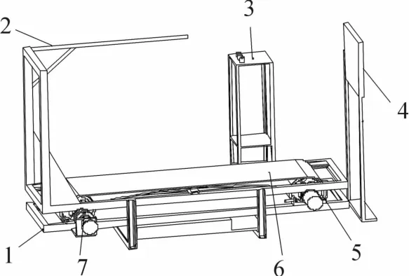
Fig.1 Speed Skating Starting Trainer Structure
3 Design and analysis of working p rincip le of hyd rau lic system
The schematic diagram of the hydraulic system of the speed skating starting trainer is shown in Fig 2.
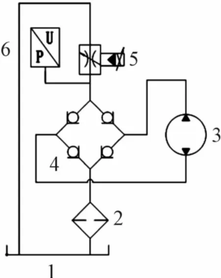
Fig.2 Princip Ie of hyd rau Iic system fo r speed skating start training device
The power of the hydraulic pump 3 comes from the athlete,and the speed is determined by the action of the athlete.The resistance is adjusted by changing the opening size of the electro-hydraulic proportional throttle valve 5.The bridge circuit composed of oneway valvemakes it possible to adjust the resistance by using the electro-hydraulic proportional throttle valve 5 whether it is oil inlet or oil return.The pressure sensor 6 and the speed sensor can monitor the resistance and speed in real time,which can meet the needs of the speed skater’s starting training.
4 Simu lation analysis of hyd rau lic circuit characteristics of speed skating starting trainer based on AM ESim
The hydraulic pump is driven by an electric motor.The input is torque and speed(angular speed),and the output is the pressure and flow of the liquid[3-4].If the loss of the hydraulic pump during the energy conversion process is not considered,the output power is equal to the input power,that is,their geometric power is

Where:Tis the geometric torque of the hydraulic pump;ωis theangular speed of hydraulic pump.

Fis the force the athlete exerts on the trainer,and this force changeswith both legs.
The flow coefficientCqis a function of the number of flowsλand the ratior:Cq=f(λ,r)
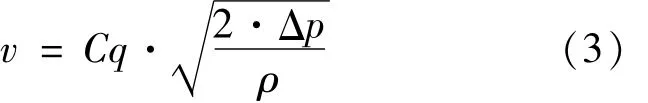
From thiswe can get the average flow velocity as:
The output flowQis:
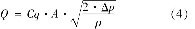
Where:Ais the throttle area;Cqis the flow coefficient;ρis the Density of hydraulic oil.
Because the other end of the throttle valve is directly connected to the fuel tank,the pressure at the other end is 0,so the pressure drop is equal to the pressure at the front end of the throttle valve:Δp=p.Excluding flow loss,Q=qin the system.
Simultaneously(1)(2)and(4),we can get the functional relationship betweenqandAas:

The functional relationship between p andAis:

As shown in Fig.3,simulate the athlete standing on the trainer.The athlete kicks his legs to the sides.The forces generated by the left and right legs areF1andF2.Their horizontal component forcesandgenerate speed and torque to the pulley.We can assume the process as:the athlete drives the belt to rotate with a certain force,and then the force stops functioning after reaching the limit position.After stopping the action,the belt stops quickly,and then the other leg starts to exert force tomake the belt rotate in the other direction.Based on this we establish amathematical model of the speed of the pulley to simulate themovement of the athlete.And input this functionmodel into the system,and drive other parts of the system to work and simulate.

Fig.3 MechanicaImode Iof speed skating starting trainer
A simulation model of the speed skating starting traineris established,as shown in Fig.4[5].Among them,the motor input signal is based on the above analysis.The athlete sends a force to drive the pulley to rotate,and uses the rotation speed of the pulley as a signal input system.Set the initial speed to 0 r/min,after a uniform acceleration to 200 r/min,there is a short hold,and then the speed quickly drops to 0 r/min,and then force is applied in the other direction.Hold for a short time,and the final speed is quickly reduced to 0 r/min.Taking this as a cycle,a function model(as shown in Fig.5)is established as an athlete’s analysis of the input power of the system.
The speed skating starting training device adjusts the resistance of the system by adjusting the opening of the throttle valve,so that the athletes can train with different strengths[6].Therefore,we hope that the change of resistance is linear and convenient for athletes to adjust.According to equation(6),we know thatwhen the flow rate andCqare constant,the relationship between the opening area andΔpis:
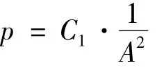
Wherecis a proportionality coefficient and is constant.Le

Fig.4 Speed skating starting trainer sim u Iation mode I

Fig.5 Motor speed
In AMESim,we set a global parameter:x.Whenxchanges linearly,the system pressurepalso changes linearly.Then batch process the global parameterx,with a set value of 0.07,a step size of 0.009,and a number smaller than the current value of 4.Then the minimum value ofxis 0.025,the maximum value is 0.07,and the number of simulations is 5.Set the orifice area of the throttle to 1/sqrt(x)mm2and the orifice hydraulic diameter tosqrt(4/sqrt(x)*PI)mm.The pump displacement of the hydraulic pump is set to 50 cc/rev,and the typical speed of pump is500rev/min.Set the relief valve cracking pressure of the relief valve to 10 MPa.All others are simulated with default settings[7-8].
As shown in Fig.6,it is themotor torque curve under different opening sizes of the throttle valve.Different colored curves represent different opening sizes.Because the global parameter x is set,the magnitude of the torque change in each simulation is basically the same It simulates that the skating starting trainer can adjust different resistances linearly.

Fig.6 Torque curve
Fig.7 shows the pressuremeasured at the front end of the throttle valve.After the rectification of the check valve,the pressure values measured by the pressure sensors are all positive,and the size of the throttle valve opening under the control of global parametersmakes The magnitude of the change is also basically the same.
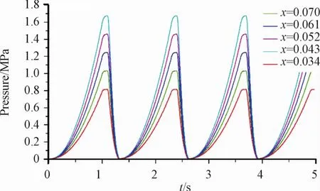
Fig.7 Pressu re curve
Similarly,the flow through the throttle flow curve valve is rectified by the check valve,so that the flow is in one direction.And the system input speed is only one set,so when the flow loss is not considered,the small flow in the different openings of the throttle valve does not change,so there is only one set of flow curve.
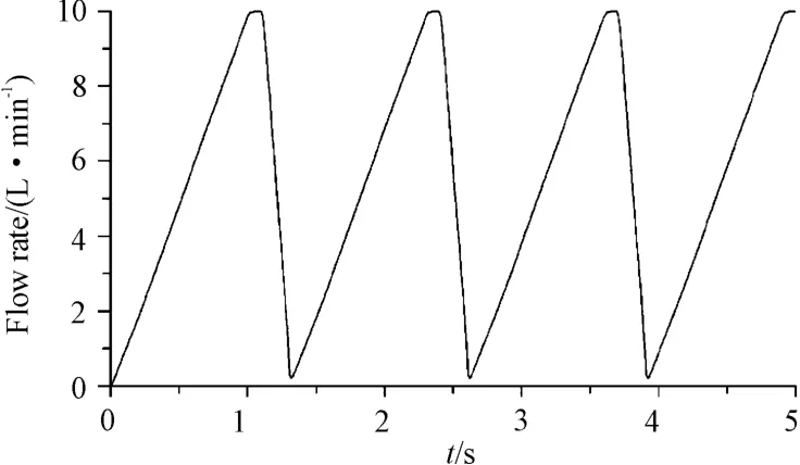
Fig.8 FIow curve
5 Conclusions
The hydraulic circuit system of a speed skating starting trainer ismainly designed.The AMEsim simulation model of the hydraulic circuit of the speed skating starting trainer is used to complete the simulation analysis of the circuit characteristics.By changing the area of the orifice,the laws of motion,torque,pressure and flow characteristics are analyzed.Through the simulation,we can draw a conclusion that the system can well simulate the training needs.Using this training device to train,we can correct the starting posture of athletes and improve the control of athletes’strength,so as to improve the training efficiency and achieve higher sports performance,and also provides a reference for the practical application debugging.

- 机床与液压的其它文章
- Study on Face detection method based on lightweight convolutional neural network
- Application of genetic optim ization lvq neural network in equipment fault diagnosis system
- Research on sliding mode control of manipulator based on RBF neural network optim ized by bionic swarm intelligence
- Research on bearing fault diagnosis technology based on deep convolution neural network
- Research on the application of improved machine learning collaborative recommendation algorithm in intelligent control
- Design of liquid filling machine positioning system based on RBFneural network activedisturbance rejection controller