Influences of flow rate and baffle spacing on hydraulic characteristics of a novel baffle dropshaft
Xi-chen Wng ,Jin Zhng *,Zong-fu Fu Hui Xu Ting-yu Xu Chen-lu Zhou
a College of Water Conservancy and Hydropower Engineering,Hohai University,Nanjing 210098,China
b The Eastern Route of South-to-North Water Diversion Project Jiangsu Water Source Co.,Ltd.,Nanjing 210019,China
Received 20 September 2019;accepted 8 April 2020
Available online 7 September 2020
Abstract Due to limited flow capacity and the instability of the asymmetric structure of traditional baffle dropshafts,a novel baffle dropshaft with a symmetric structure,adopting the construction shield well directly,is proposed for large-range flow discharge in deep tunnel drainage systems.In this study,a two-phase flow field of the novel baffle dropshaft with three different baffle spacings was simulated at seven different flow rates with a three-dimensional(3D)numerical model verified with experiments,to study hydraulic characteristics of this novel baffle dropshaft.The results show that the novel baffle dropshaft has a remarkable energy dissipation effect.Baffle spacing of the novel baffle dropshaft has a greater effect on flow patterns and baffle pressure distributions than the comprehensive energy dissipation rate.Flow rate is a critical issue for the selection of baffle spacing in the design.Some guidance on baffle spacing selection and structure optimization for the application of this novel baffle dropshaft in deep tunnel drainage systems is proposed.
© 2020 Hohai University.Production and hosting by Elsevier B.V.This is an open access article under the CC BY-NC-ND license(http://creativecommons.org/licenses/by-nc-nd/4.0/).
Keywords:Deep tunnel drainage system;Baffle dropshaft;CFD;Experimental study;Two-phase flow field
1.Introduction
Baffle dropshafts are one of the main types of energy dissipation structures in municipal drainage systems(Stirrup et al.,2012).Several staggered baffles are positioned for the purpose of water transmission and energy dissipation(Margevicius and Lyons,2012).At present,the main type of baffle dropshaft structure is divided into a wet zone and a dry zone by a partition(Fig.1(a)):the wet zone,with baffles interlaced,is a water flow passage,and the dry zone is an exhaust passage,with vent holes arranged on the partition to connect the wet zone and the dry zone.Based on the prototype of the No.4 dropshaft in the Euclid Creek Tunnel Project,Margevicius et al.(2010)carried out an experimental study of this type of baffle dropshaft,and verified that its overflow rate was under 8.5 m3/s.Lyons and Odgaard(2010)and Lyons et al.(2011)studied the relationship between hydraulic characteristics and geometric parameters of the baffle dropshaft in a recent Iowa Institute of Hydraulic Research(IIHR)baffle dropshaft project for the Regional Municipality of York,Canada,and adopted the free overfall theory to optimize the dropshaft design applied in the Fall Creek/White River Tunnel Project in Indianapolis,USA.However,the overflow rate of the optimized baffle dropshaft was less than 13 m3/s(Odgaard et al.,2013).With the continuous acceleration of urbanization,existing drainage network systems cannot meet the demand of urban rainwater drainage,and deep tunnel drainage systems have gradually become an effective measure of solving the problem of urban water logging(Hassani et al.,2015;Men et al.,2015;Ding et al.,2016;Hu et al.,2018;Rubinato et al.,2019).As the first deep tunnel drainage project in China,the Guangzhou Donghaochong Deep Sewerage Tunnel Project also adopts this type of baffle dropshaft,and the maximum overflow rate has been raised to 32 m3/s(He et al.,2017).Based on this project,Wang et al.(2015a,2015b)studied the functions of baffles in the baffle dropshaft,analyzed its hydraulic transition characteristics,and proposed a theoretical basis for the selection of baffle spacing.Wang et al.(2015c,2015d)optimized the design of the baffle dropshaft in the Guangzhou Donghaochong Deep Sewerage Tunnel and put forward the constraint conditions.A deep tunnel drainage system project is going to be constructed as well in Shanghai City,and the designed drainage flow rate is between 0 and 80 m3/s.However,the overflow rate of the traditional baffle dropshaft mentioned above cannot meet the drainage requirement of the project.Therefore,a novel baffle dropshaft with a new structure is proposed by Ma et al.(2020)for a deep tunnel drainage system with a large flow rate.
As shown in Fig.1(b),the novel baffle dropshaft is divided into an inner overflow well,which is the wet zone,and an outer exhaust well,which is the dry zone.The most distinctive feature of the baffle dropshaft structure is that it directly uses the construction well reserved for shield machine entry and exit(i.e.,shield construction well)as the exhaust outer well.Several semicircle baffles are interlaced in the inner well to form an overflow passage.Vent holes are set under baffles to connect the inner and outer wells.Compared with the traditional baffle dropshaft,the novel baffle dropshaft makes full use of the large diameter of the shield construction in order to enlarge the internal overflow passage,so that the overflow rate of the shaft is greatly improved.Moreover,the symmetrical structure arrangements of the inner wet zone and outer dry zone in the novel baffle dropshaft are more stable than the structure arrangement of the half wet zone with interlaced 1/4 circle baffles and the half dry zone in the traditional baffle dropshaft.Since the novel baffle dropshaft was first proposed,there has been hardly any hydraulic research result on this type of dropshaft.In this study,the hydraulic characteristics of this novel baffle were investigated by combining threedimensional(3D)computational fluid dynamics(CFD)numerical simulation with experimental verification,in order to study the influences of flow rate and baffle spacing on the hydraulic characteristics of this type of dropshaft,and to provide a scientific basis for optimization of dropshaft design in deep tunnel drainage systems.
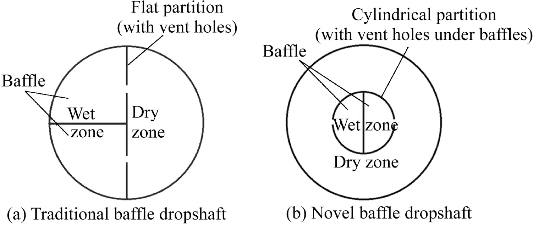
Fig.1.Schematic diagram of plane structure of traditional and novel baffle dropshafts.
2.Model establishment and verification
2.1.Model establishment
In this study,a 3D novel baffle dropshaft numerical model was built through ANSYS FLUENT.As shown in Fig.2,the computational domain of the present model consists of an inner overflow well whose upper part is connected to a section of the inflow channel,and an outer exhaust well whose lower part is connected to an upstream tunnel and a downstream tunnel.The diameter of the inner well is 10 m and that of the outer well is 30 m.The inflow channel is 21 m long and 7 m wide,with an inlet width of 1.5 m,having a gradual expansion connection with the upper part of the inner well.The inner well is interlaced equidistantly with several semicircle baffles,and the bottom of the first baffle has the same height as the bottom of the inflow channel.On the wall of the inner well,a 0.4 m×0.8 m square vent hole is set under each baffle,and a 1.8-m-high outlet is set on the downstream side at the bottom.The diameter of the tunnel is 9 m,and the bottom of the tunnel is 2.5 m higher than that of the dropshaft.The tunnel,in which the upstream section is 40 m long and the downstream section is 100 m long,is connected to the bottom of the outer well through the middle line.The tunnel is placed horizontally,and the influence of the slope is ignored.The dimensions of the entire numerical model are 170 m in length,30 m in width,and 44.72 m in height,established on a scale of 1:20,which is the same as the physical model for the validation.

Fig.2.Computational domain of 3D novel baffle dropshaft.
The inflow channel inlet and the upstream tunnel inlet are both set with an open channel boundary provided with free surface water flow with a certain flow rate,to simulate the flow from the upper pipeline system and that from other dropshafts to the upstream tunnel,respectively.The downstream tunnel outlet is set with a pressure outlet boundary.The top ceiling of the inflow channel and the dropshaft,connected to ventilation facilities,are set with a pressure outlet boundary with an atmospheric pressure.The remaining are wall boundaries with the effect of surface roughness ignored.
In the present 3D novel baffle dropshaft numerical model,the volume of fluid(VOF)method is used to track the free surface between air and water,both of which are treated as incompressible fluids without mass or heat exchange between them.Because the novel baffle dropshaft has a complex structure and bending flow,the realizable k-εmodel is selected for its advantages in simulating the turbulence flow with strong streamline curvatures and vortices.The standard wall function is adopted to deal with the near wall flow.
2.2.Grid independence test
The computational domain is meshed by both structural and non-structural grids.The inflow channel,inner well,and tunnels are meshed with hexahedron grids,and the outer well is meshed with tetrahedral grids.Mesh refinement is carried out for the inner well.
The numerical model of the novel baffle dropshaft with 3-m baffle spacing was used as an example for grid independence testing.By increasing and decreasing the mesh size,the 3-m baffle dropshaft model was meshed with a cell number varying from 1 255 225 to 3 717 681.Steady numerical simulation at the inlet flow rate of Qin=40 m3/s was carried out for the model with different mesh sizes,and the average water velocity(vw)and water level(Hw)at the cross-section at a distance of 40 m from the downstream tunnel inlet were extracted to calculate the comprehensive energy dissipation rate(η)of the dropshaft(Eq.(1)).

where E1and E2are the total water head,including position head,pressure head,and velocity head,at the inflow channel inlet and the cross-section at a distance of 40 m from the downstream tunnel inlet,respectively.
An error analysis of the results with different meshes was carried out based on the model with a cell number of 2 968 125(Table 1).As shown in Table 1,when the cell number is over 1 922 678,the relative errors of the average velocity and the water level are less than 1.2%for all mesh sizes,and the relative error of the comprehensive energy dissipation rate is less than 0.05%.The results have reached mesh independence.Taking both calculated accuracy and efficiency into account,the numerical model of the 3D novel baffle dropshaft with 3-m baffle spacing was meshed into 2 968 125 cells.A similar mesh generation method was implemented in the following study models with different baffle spacings.

Table 1 Comparison of novel baffle dropshaft with 3-m spacing at different mesh sizes.
2.3.Model verification
A deep tunnel energy dissipation system test bench on a scale of 1:20 was constructed according to gravity similarity.As shown in Fig.3,the test bench,which adopts the water recycling system,consists of back pools,stable pools,connecting pipes,centrifugal pumps,valves,a water inlet tank,and a physical model of dropshaft with a connecting tunnel section.Based on the test bench,physical model tests of the 3-m novel baffle dropshaft,which has the same structural and geometric dimensions as with the 3D numerical model mentioned above,were carried out at Qin=20,40,60,and 80 m3/s to verify the present numerical model.
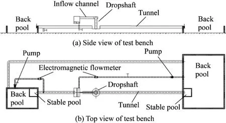
Fig.3.Schematic diagram of deep tunnel energy dissipation system test bench.
In the tests,Hwand vwwere measured by a steel ruler and a photoelectric propeller velocimeter on the inflow channel inlet and the cross-section at a distance of 40 m from the downstream tunnel inlet,respectively,andηwas calculated according to Eq.(1).Comparison ofηin the physical model test and the 3D numerical model test(Table 2)shows that the errors of numerical results are slightly larger than those of the experimental results,and the absolute errors(Δ)are under 1.5%,a value that includes the experimental error related to measurement accuracy,as well as the calculation error of numerical model caused by the methodology,simplification of boundaries,mesh quality,etc.Furthermore,a comparison of the flow patterns observed in the physical model test with those obtained from the numerical model shows that their characteristics at different values of Qinare quite similar:water drops between the staggered baffles,forming an aerated flow(marked with red ovals in Fig.4(a)),in whichαis the volume fraction of water.With the increase of Qin,a water gushing phenomenon(marked with red ovals in Fig.4(b))occurs on the top baffle at the opposite side of the inflow channel,the water surface near the downstream tunnel(marked with red ovals in Fig.4(c))is strongly affected by the outflow at the bottom of the inner shaft,and the flow passage is gradually blocked,causing a water spraying phenomenon(marked with red ovals in Fig.4(d))in the vent holes.

Table 2 Comparison of comprehensive energy dissipation rate of experimental and numerical results at different inlet flow rates.
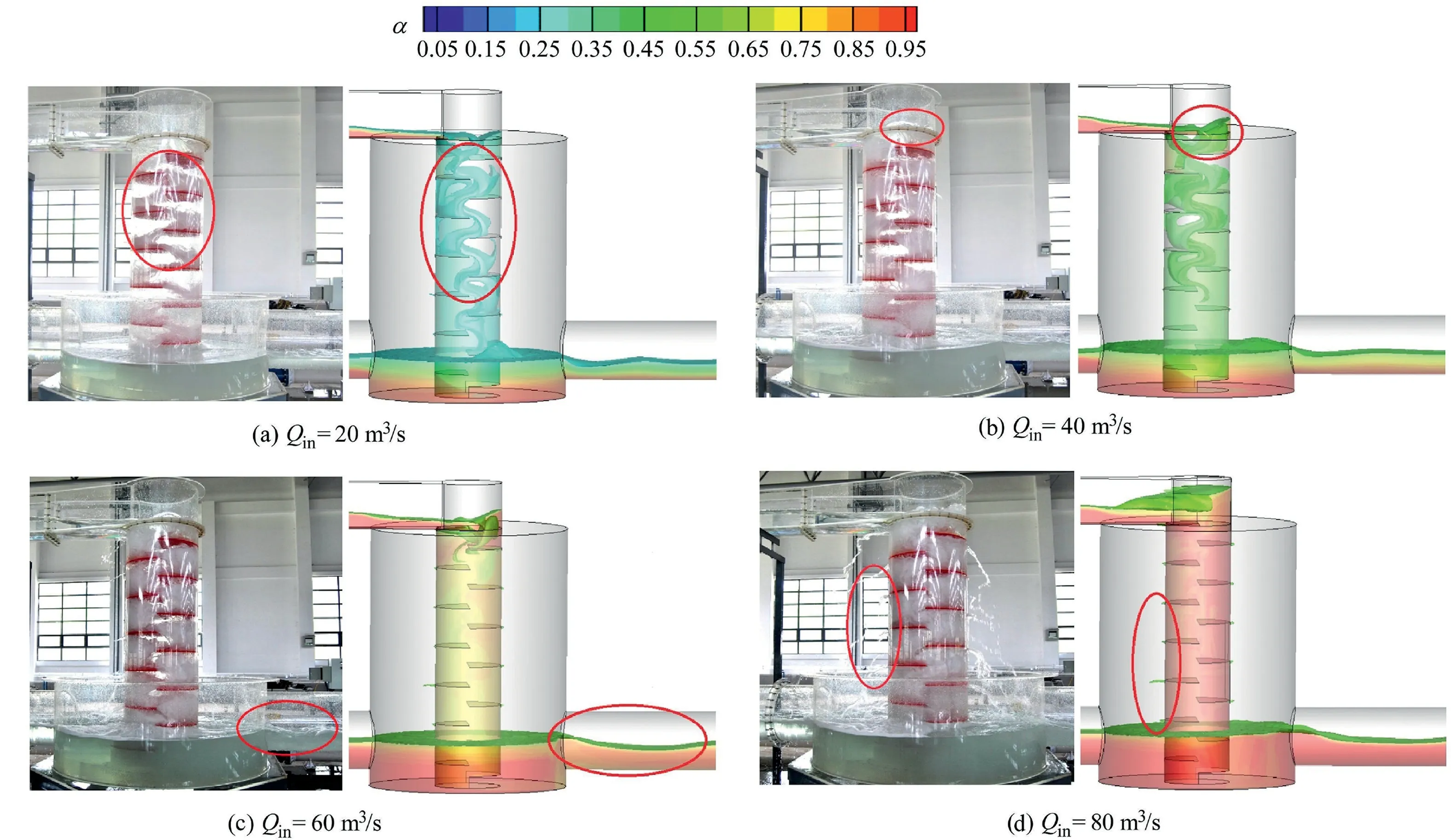
Fig.4.Comparison of experimental and computational flow patterns in 3-m dropshaft model at different inlet flow rates.
Consequently,according to the comparisons above,the present 3D novel baffle dropshaft numerical model was verified and can be used as an important scientific tool to study the hydraulic characteristics of the novel baffle dropshaft.
3.Case study and analysis
To study the characteristics of air-water flow and the adaptability of baffle spacing and flow rate in the novel baffle dropshaft,three numerical models with the same geometry domain and model setups with only changes in baffle spacing(i.e.,3,4,and 5 m)were constructed.They are referred to here as the 3-m,4-m,and 5-m model.Simulations were run with seven Qinvalues(i.e.,20,30,40,50,60,70,and 80 m3/s)(Table 3).Based on the simulation results,the influence of Qinonη,flow pattern,and pressure(p)was investigated.Some guidance on baffle spacing selection and structure optimization for the application of this novel baffle dropshaft in deep tunnel drainage systems is proposed.
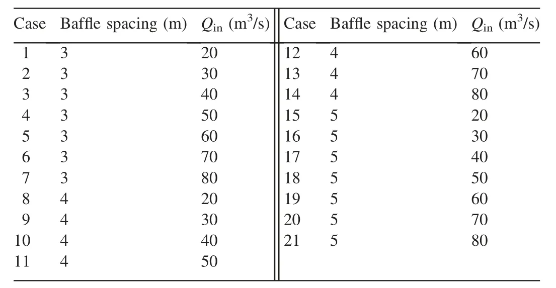
Table 3 Study cases for adaptability of baffle spacing and flow rate in novel baffle dropshaft.
3.1.Influence on energy dissipation rate
Based on Eq.(1),ηbetween the inflow channel inlet and the cross-section at a distance of 40 m from the downstream tunnel inlet was calculated for each case.The curves ofηwith Qinfor three dropshafts with different baffle spacings are depicted in Fig.5.
The results show that,when Qinis low,ηvalues for the three models reach or even exceed 95%,and the differences between the values are small.With the increase of Qin,η shows a downward trend,and the differences between the three spacing shafts increase.However,ηstill exceeds 90%when Qinis 80 m3/s.As shown in Fig.5,the slopes ofη decreasing with Qinfor the three models are different:the slope for the 4-m model shows a linear change,and the slope for the 5-m model decreases slowly at first and then more rapidly,while that for the 3-m model decreases rapidly at first and then more slowly.The three slope curves intersect around 60 m3/s and are divided into two sections:when Qinis lower than 60 m3/s,the dropshaft with larger baffle spacing has a slightly largerη;when Qinis higher than 60 m3/s,the dropshaft with smaller baffle spacing has a largerη.
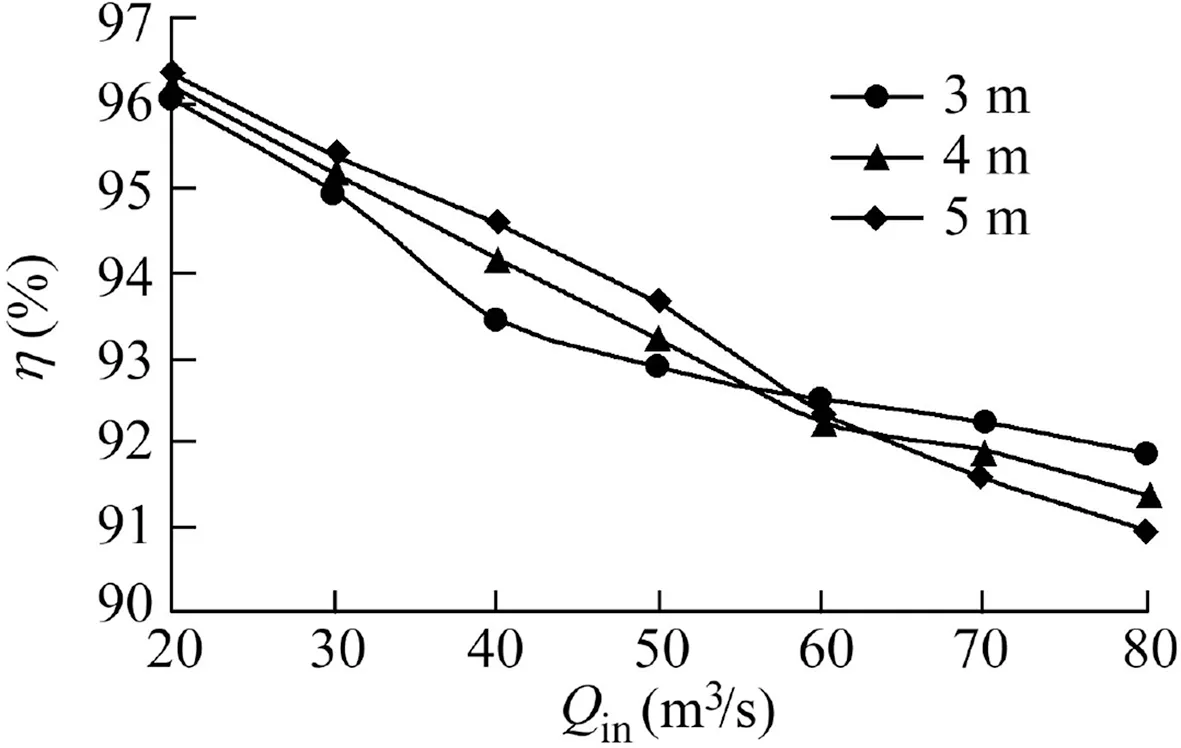
Fig.5.Comprehensive energy dissipation rate of dropshaft with different baffle spacings at different inlet flow rates.
According to the calculation results and analysis described above,the following can be observed:
(1)The novel baffle dropshaft,which uses the construction shield well as an external exhaust well and staggered baffles in the inner flow passage as energy dissipaters,has a remarkable energy dissipation effect.
(2)Theηvalues of the three novel baffle dropshafts decrease with the increase of Qin,but remain at a high level,meeting the design requirements for a deep tunnel system.
(3)The baffle spacing of the novel baffle dropshaft has little influence onη.Therefore,when selecting the spacing and optimizing the structure design for a novel baffle dropshaft,factors such as flow pattern and p should mainly be taken into account.
3.2.Influence on flow pattern
3.2.1.General flow patterns
The present 3D numerical model of the novel baffle dropshaft adopts the VOF method to track the air-water interface,whereαequals 0.5.Because of the influence of the staggered baffles in the inner well,air and water are highly mixed,and thus it is difficult to depict the interface accurately.Still,the flow patterns for each case can be analyzed qualitatively.In order to clearly describe the overall water distribution in the dropshaft,an x-z plane was extracted at the middle line along the main tunnel flow direction for each model,and the contour ofαon the plane for different values of Qinis shown in Fig.6.The following observations can be made:
(1)The general flow patterns in this novel baffle dropshaft at different Qinvalues are similar,and can be summarized as follows:water enters the inner well from the inflow channel,falls on staggered baffles,forming an S-shaped reciprocating flow,flows out of the inner well from the bottom outlet,converges with the water from the upstream tunnel at the outer well bottom,and then pours into the downstream tunnel.However,there are still some major differences in the detailed flow patterns between cases.
(2)Air entrainment in the flow is significant in the inner well because of the influence of staggered baffles,and it tends to cause congestion in the flow passage and affect the flow discharge.At a low value of Qin,the congestion levels of the flow passage in all three models are lower.However,when Qinincreases,the clogging in the inner well is aggravated,so that the phenomena of backwater at the upper part of the inner well and water spray under the baffles become more pronounced,and the disturbance of water gushing from the inner well in the bottom is more aggravated,resulting in partial blockage at the downstream tunnel entrance.
(3)Because of the difference in baffle spacings,the crosssectional area of the flow passage varies.Therefore,the clogging of the inner well in the 3-m model is the most significant at different values of Qin,and it is least in the 5-m model.When Qinis high,especially when it reaches 80 m3/s,the flow passage in the inner well of the 3-m model is almost completely blocked by water and all vent holes are spraying,so the water cannot easily flow and forms a backflow from the upper part of the inner shaft to the inflow channel.At the same value of Qin,when the baffle spacing increases,that is,when the cross-sectional area of the flow passage increases,the water flow discharges smoothly from the inner well and the flow passage is not easily blocked.However,due to the increase of the baffle spacing,the drop height of the water flow between baffles of each layer increases,and the impact by the outflow from the bottom of the inner well increases,so the resulting surge readily causes partial plugging of the downstream tunnel inlet.
As mentioned above,the air-water flow patterns are complex in this type of dropshaft because of the interlaced baffle structure,and therefore it is necessary to analyze the overall p distribution in the inner well.Through comparison of the contours of p on the middle-line plane of the inner well at seven different values of Qinfor the three models,the influences of baffle spacing and Qinon the p distribution in the inner well can be clarified.At a low value of Qin,p distributions in the inner well for the three models are similar,with lower p values occurring in the upper inner well and higher p values occurring in the lower inner well.With increased Qin,p in the lower part of the inner well increases,while p in the upper part varies in the three models(Fig.7).In the 3-m model,p in the upper part of the inner well increases due to the blockage of the flow passage.In the 4-m and 5-m models,p decreases because of the increase of the velocity in the unobstructed flow passage.Particularly in the 5-m model,p decreases to negative values in the low-pressure zone under the upper baffles.
3.2.2.Detailed flow patterns
From the analysis of the overall flow patterns in the three dropshaft models at different levels of Qin,it can be seen that the hydraulic phenomena in two-phase flow in the upper part and at the bottom of the dropshaft are complex,so the local detailed flow patterns were further analyzed.
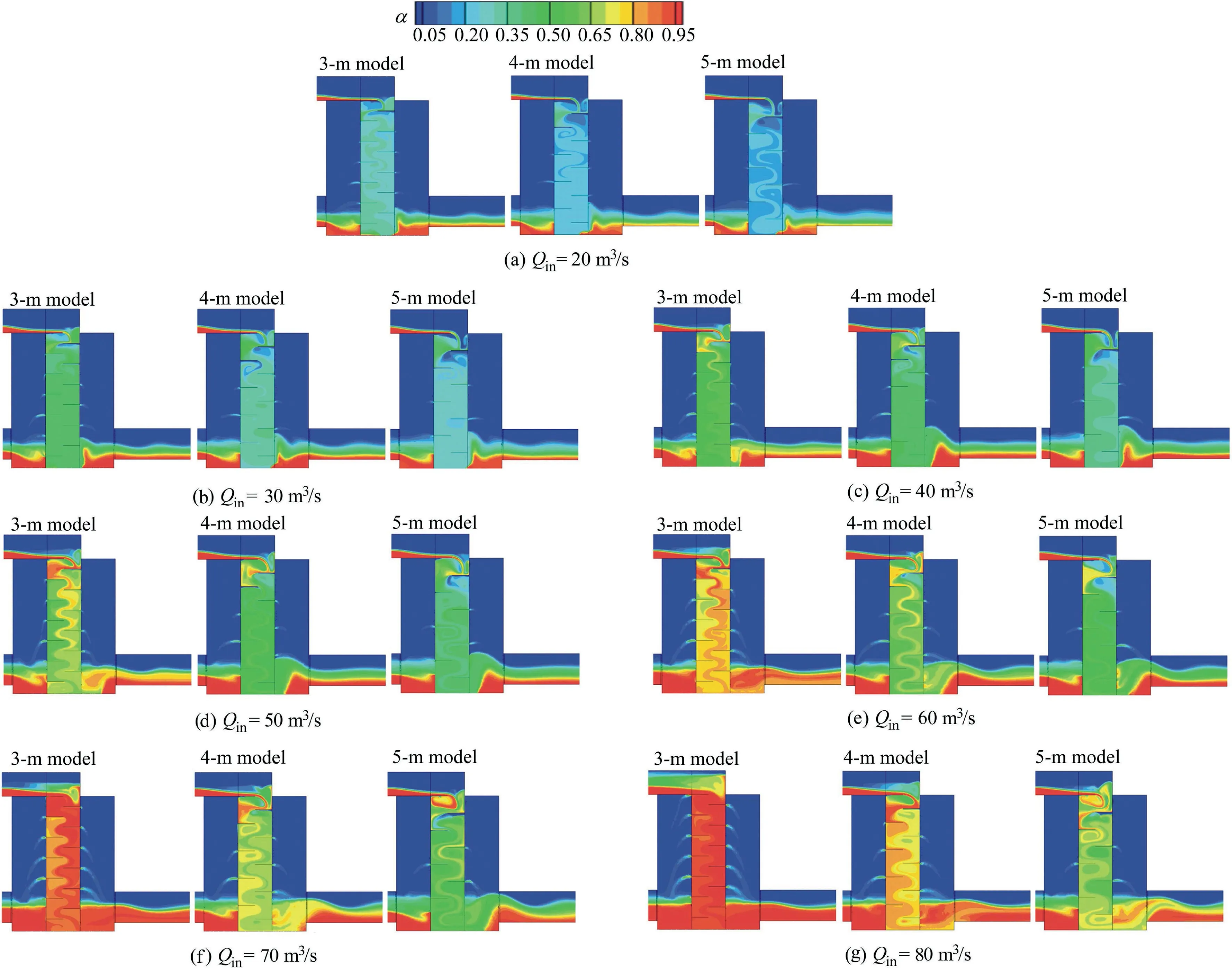
Fig.6.Water distribution on middle-line plane in three dropshaft models at different inlet flow rates.

Fig.7.Pressure distribution on middle-line plane in three dropshaft models at inlet flow rate of 80 m3/s.
Drawingαand velocity vectors on the upper part of the extracted middle-line plane in the three novel baffle dropshaft models at different levels of Qin(Fig.8)shows that,for all conditions,some up-and-down vortices formed by the impact of falling water flow on the staggered baffles exist in the inner well and affect the discharge of water.In particular,there is a clear vortex between the top baffle on the other side of the inflow channel and the sidewall of the inner well.When the flow rate increases,the position of the flow center impacting the top baffle gradually moves to the wall with the increase of flow kinetic energy,so that the vortex is squeezed and the local water level rises,resulting in a backflow to the inflow channel.With smaller baffle spacing,the backflow phenomenon is more evident.In the 3-m model,the backflow even enters the inflow channel at a high value of Qinbecause the flow passage is severely blocked.Moreover,there is a clear inward air supply at the vent holes on the top layer of the inner well in the three models at a low flow rate.However,when the flow rate increases in the 3-m model,the inward air supply phenomenon gradually abates because the congestion in the inner well is aggravated,and water spray occurs at the vent holes.In the 4-m model,there is less congestion in the inner well,so there is still a slight inward air supplement at a high flow rate.The 5-m model has the least amount of congestion,and the flow passage is smooth,so the inward air supplement is still significant and greater velocity vectors exist,resulting in low-p zones under the top baffles(Fig.7).
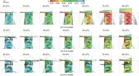
Fig.8.Water and velocity distributions in upper part of middle-line plane in three dropshaft models at different inlet flow rates.
The distributions ofαand velocity vectors at the bottom of the extracted middle-line plane between the three models were compared.Although there are some small differences in flow patterns at the bottom for the three models,the variations of flow patterns with flow rate are similar.At a low value of Qin,the water level near the upper wall of the inner well outlet rises because of the disturbance of the aerated outflow,resulting in an undulated water surface near the inlet of the downstream tunnel.As Qinincreases,the inertia of the outflow from the inner well increases,and the position of the rising water surface gradually moves away from the inner well,and even enters the downstream tunnel at a high value of Qin,resulting in partial blockage at the inlet of the downstream tunnel.In order to compare the degree of blockage in the downstream tunnel inlet in the three models at different levels of Qin,the distributions ofαand the velocity vectors in the cross-section at the inlet of the downstream tunnel are depicted in Fig.9,in which the red sections represent water withαabove 0.5.The water flow and the ventilation at the downstream tunnel inlet in the three models are smooth at a low value of Qin.However,with the increase of Qin,the cross-sections in the 4-m and 5-m models are gradually blocked with the undulated water surface,because of the disturbance of the outflow from the inner well.The degree of blockage in the 5-m model at the flow rate of 70 m3/s is the most significant,resulting in air being squeezed from near the upper half of the tunnel wall.As the direction of the outflow from the inner well changes,the position of the rising water surface moves into the downstream tunnel,and the water surface at the inlet cross-section becomes smooth.
3.2.3.Influence on baffle pressure
In the novel baffle dropshaft,water flow falls between staggered baffles,and the impact pressure of water flow on the baffles is related to the stability of the dropshaft structure.Therefore,the contours of p on the baffles in the three models at different levels of Qinwere extracted for analysis.When Qinis low in the three models,p on the baffles is low and the difference in p is insignificant(Fig.10(a)).With the increase of Qin,p on the upper baffles of the inner well decreases and that on the lower baffles increases.With a higher level of Qinand larger baffle spacing,the difference in p between the lower and the upper baffles in the inner well is greater(Fig.10(b)).p on the top baffle of the 5-m model decreases to a negative value with a high level of Qin,resulting in a potential threat to the stability of the dropshaft structure.In the 3-m model,in contrast,the gradient of p is small and p on all baffles is positive because of the significant blockage of the flow passage.
The maximum pressure(pmax)and minimum pressure(pmin)on baffles of the three models at seven different levels of Qinare extracted and shown in Fig.11.pmaxon the baffles in the three models increases with Qin,but the difference is small,except for the fluctuations around Qinat 60 m3/s in the 5-m model.The variation of pminis less than that of pmaxat different levels of Qin.The pminin the three models at a Qinvalue between 20 and 60 m3/s do not vary much,but begin to vary significantly with Qinvalues from 60 m3/s upward.The pminin the 3-m model rises because of the blockage of flow in the inner well,and the pminin the 5-m model decreases,since the flow passage in the 5-m model is smooth at a high value of Qinand the flow velocity increases.In addition,p in the inner well is affected by the degree of blockage at the downstream tunnel inlet.
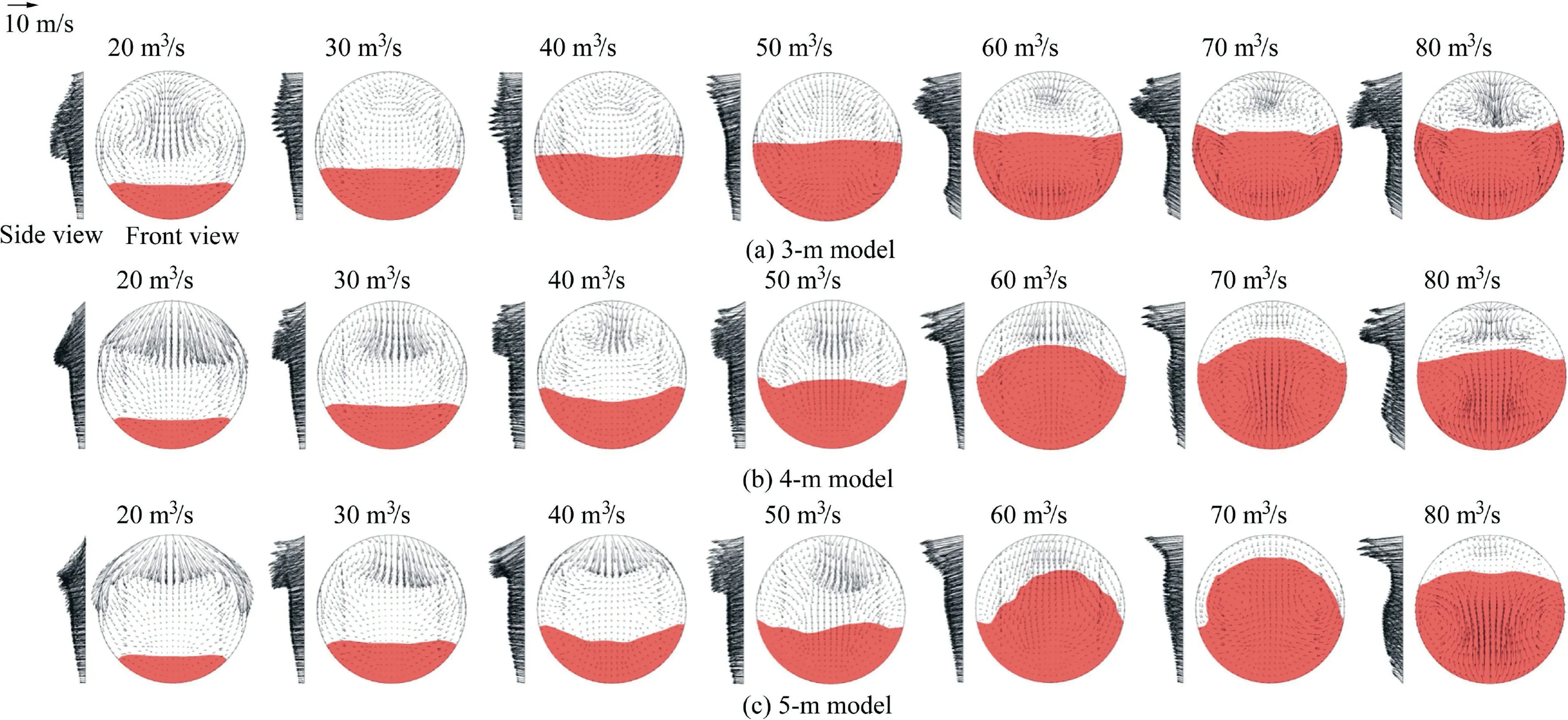
Fig.9.Water and velocity distributions at downstream tunnel inlet cross-section in three models at different inlet flow rates.
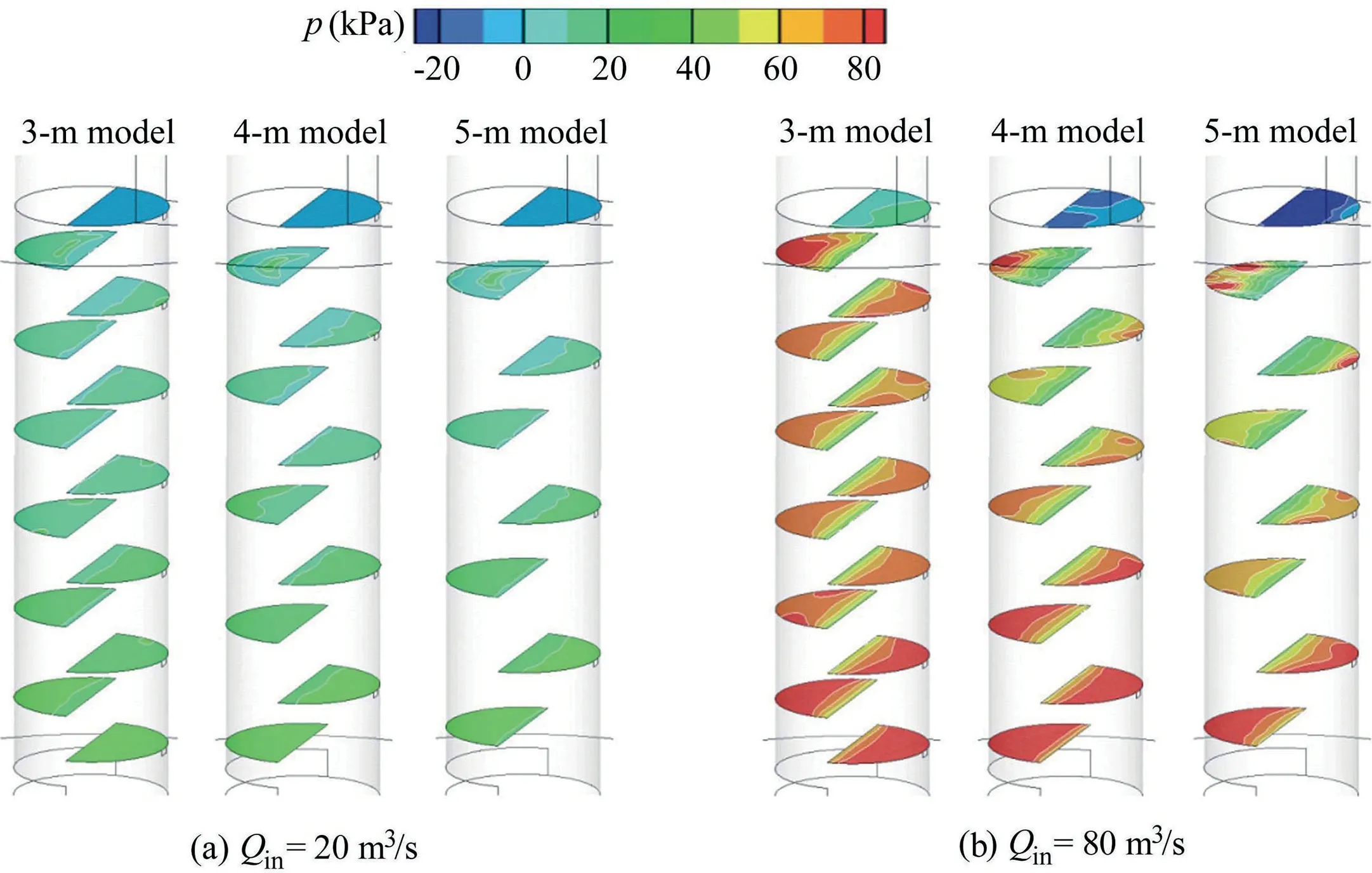
Fig.10.Pressure distribution on baffles in three dropshaft models at different inlet flow rates.
3.2.4.Adaptability of baffle spacing and flow rate
Based on the analyses above,the curves ofηin the three models cross at Qin=60 m3/s,where the extreme p on the baffles also starts to change significantly.This is mainly attributed to the change of flow patterns,and Qin=60 m3/s is the key flow rate at which the flow pattern changes in the three models.When Qinincreases to about 60 m3/s,blockage of the flow of the inner well in the 3-m model begins,and the downstream tunnel inlet in the 5-m model also starts to be blocked by the rising water surface,resulting in changes of parameters throughout the flow field in the dropshaft.
Consequently,in the design of the proposed novel baffle dropshaft for a specific project,the local extreme and conventional rainfalls should be considered when selecting the baffle spacing.For the geometry of the dropshaft described in this paper,Qin=60 m3/s is the key flow rate in the design.When Qinis lower than 60 m3/s,the selection of baffle spacing has little effect;when Qinis higher than 60 m3/s,the stability of the structure caused by the p difference on baffles and the smoothness of the flow passage in the inner well should be considered.
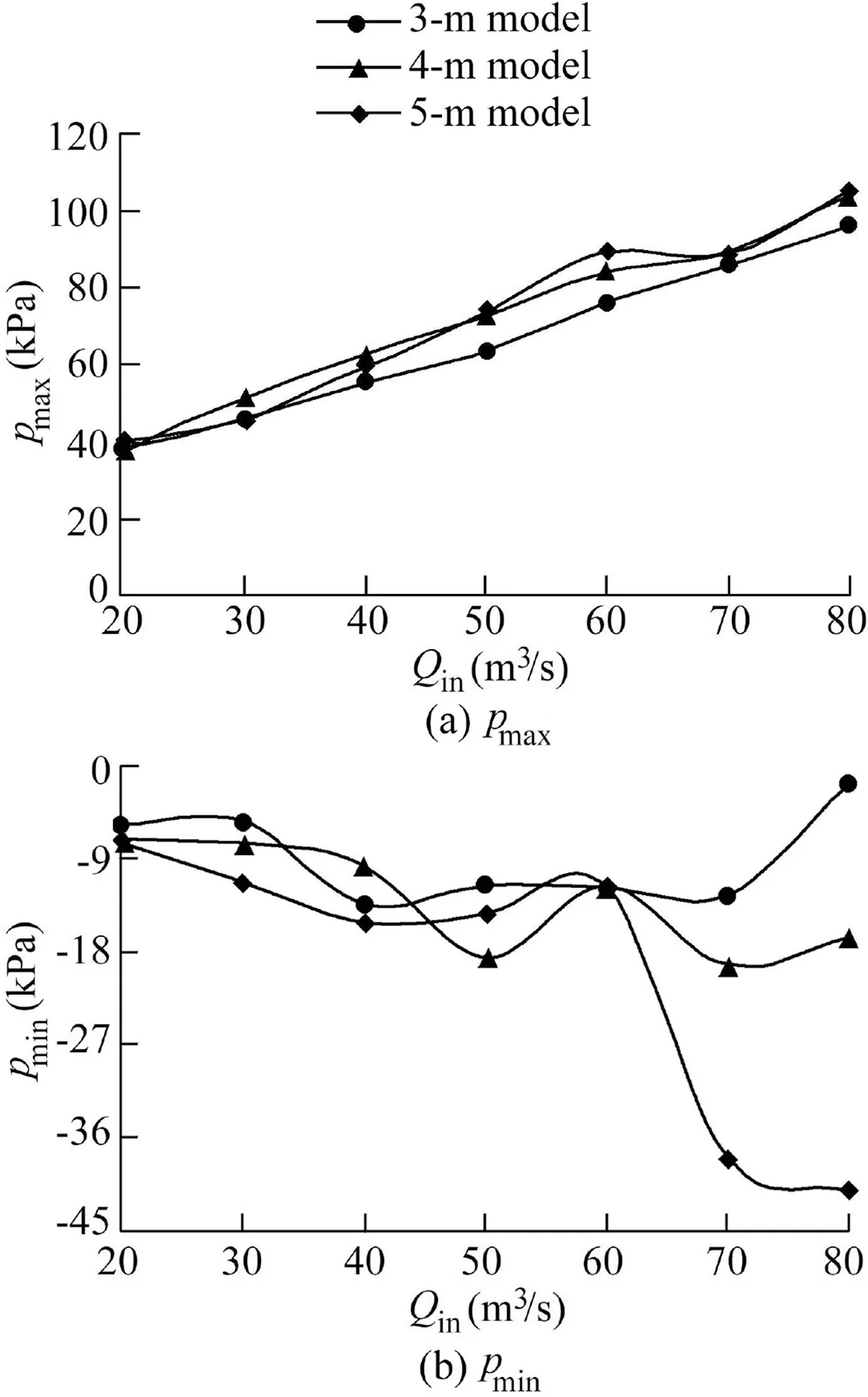
Fig.11.Maximum and minimum pressures on baffles in three dropshaft models at different inlet flow rates.
4.Conclusions
The novel baffle dropshaft described in this paper,which adopts the construction shield well directly and consists of a baffled inner overflow well and a surrounding outer exhaust well,has a higher flow capacity and more stable structure compared with the traditional baffle dropshaft.A 3D,twophase numerical model of the novel baffle dropshaft was developed based on the CFD method and verified through physical model tests.Numerical simulations of air-water twophase flow field in the innovated baffle dropshaft with three different baffle spacings(3,4,and 5 m)at seven inlet flow rates(20,30,40,50,60,70,and 80 m3/s)were carried out.Through comparison and analysis of the simulation results of the studied 21 cases from three aspects,the following conclusions are drawn:
(1)The novel baffle dropshaft has a remarkable energy dissipation effect.Its comprehensive energy dissipation rate decreases with the increase of the flow rate,but remains at a high level,meeting the design requirements for the deep tunnel system.
(2)The general flow patterns in the novel baffle dropshaft are as follows:water flow falls on the staggered baffles in the inner well and forms an S-shaped reciprocating flow pattern with an up-and-down vortex in each layer,hindering the discharge of water;a backwater phenomenon occurs at the upper part of the inner well due to the blockage of the flow passage;and an undulated water surface appears in the bottom of the outer well because of the disturbance of the outflow from the inner well.
(3)The baffle spacing of the novel baffle dropshaft has less influence on the comprehensive energy dissipation rate,but greater effects on flow patterns and baffle pressure distributions.Withtheincreaseoftheflowrate,indropshaftswithsmallerbaffle spacing,the blockage of the flow passage and backwater at the upper part of the inner well become more significant.Meanwhile,in dropshafts with larger baffle spacing,the flow passage is smooth,but the downstream tunnel inlet gets partially blocked by the rising water surface and the pressure gradient on the baffles becomes greater,threatening the structure of the inner well.
(4)Flow rate is a critical issue for the selection of baffle spacing in the design.When the inlet flow rate is less than the key number,baffle spacing has little effect on the hydraulic characteristics.When the flow rate is higher than the key number,the structure stability caused by the pressure difference and the flow passage smoothness in the inner well should be taken into account.The key inlet flow rate for the present novel dropshaft is 60 m3/s.
(5)According to the analyses and conclusions above,some suggestions are given for the optimization of the novel baffle dropshaft design in deep tunnel drainage systems:(a)the height of the top baffle at the inflow channel side should be reduced to ease the backwater phenomenon in the upper part of the inner well;(b)the arrangement of vent holes should be optimized to reduce the blockage of the flow passage in the inner well;and(c)the cross-sectional area at the junction of the tunnel and the shaft should be enlarged,to reduce the partial blockage at the downstream tunnel inlet.
Declaration of competing interest
The authors declare no conflicts of interest.
 Water Science and Engineering2020年3期
- Water Science and Engineering的其它文章
- Impacts of topographic factors on regional snow cover characteristics
- Evaluation of alum-based water treatment residuals used to adsorb reactive phosphorus
- Phosphorus removal by adsorbent based on poly-aluminum chloride sludge
- Characterization of cobalt ferrite-supported activated carbon for removal of chromium and lead ions from tannery wastewater via adsorption equilibrium
- Acclimatization of microalgae Arthrospira platensis for treatment of heavy metals in Yamuna River
- Three-dimensional modelling of shear keys in concrete gravity dams using an advanced grillage method
