Three-dimensional modelling of shear keys in concrete gravity dams using an advanced grillage method
Mahdi Ben Ftima*,St′ephane Lafrance,Pierre L′eger
Polytechnique Montr′eal,Montreal University Campus,Montreal,H3C 3A7,Canada
Received 26 September 2019;accepted 2 May 2020
Available online 25 September 2020
Abstract Contraction joint shear keys are resilient features of gravity dams that can be considered to increase the sliding safety factors or minimise seismic residual sliding displacements,allowing costly remedial actions to be avoided.This paper presents a novel,robust,and computationally efficient three-dimensional(3D)modelling and simulation strategy of gravity dams,using a series of adjacent cantilever beam elements to represent individual monoliths.These monoliths are interconnected in the longitudinal direction by 3D no-tension link elements representing the lumped shear key stiffness contributions at a particular elevation.The objective is to assess the shear key internal force demands,including the axial force,shear,and moment demands.Shear key demand-capacity ratios can then be assessed with related multi-axial failure envelopes.The 3D link element stiffness coefficients were derived from a series of 3D finite element(FE)solid models with a detailed representation of geometrical features of multiple shear keys.The results from the proposed method based on advanced grillage analysis show strong agreement with reference solutions from 3D FE solid models,demonstrating high accuracy and performance of the proposed method.The application of the proposed advanced grillage method to a dam model with two monoliths clearly shows the advantage of the proposed method,in comparison to the classical approach used in practise.
© 2020 Hohai University.Production and hosting by Elsevier B.V.This is an open access article under the CC BY-NC-ND license(http://creativecommons.org/licenses/by-nc-nd/4.0/).
Keywords:Gravity dam;Shear keys;Seismic analysis;Grillage analysis;Finite element model;Multi-scale approach
1.Introduction
Several existing gravity dams have been constructed with contraction joint shear keys between monoliths.Fig.1(a)shows a typical example of rectangular shear keys(305 mm×1 600 mm)extruded vertically and located at a vertical contraction joint.Due to the triangular shape of dam sections,the number of keys intercepted by horizontal planes is variable along the height.In the initial structural design from two-dimensional(2D)analyses of individual monoliths,these keys are not able to provide load transfer with their neighbouring dam blocks.However,a shear key can provide some load transfer and interlocking mechanisms between monoliths upon sliding initiation,leading to a threedimensional(3D)response under severe hydrostatic(flood)or seismic loads(NZSOLD,2015;FEMA,2014;Dowdell and Fan,2004;Azmi and Paultre,2002;Lund and Boggs,1994;Osterele et al.,1993).Therefore,in the safety assessment of existing gravity dams,shear keys are resilient features that can be considered to increase the sliding safety factors or minimise seismic residual sliding displacements,allowing costly remedial actions to be avoided.Numerical studies on modelling shear keys have been conducted almost exclusively in the context of seismic response of arch dams where the number of keys did not vary significantly along the height,and the keys were subjected to large initial axial forces(Jiang et al.,2011;Du and Jiang,2010;Guerra and Nuss,2007;Gunn,2005;Lau et al.,1998).In these analyses,simplified one-dimensional(1D)tangential friction contact(spring)elements were inserted between dam blocks to model contraction joints.Recently,Omidi and Lotfi(2017)introduced bidirectional shear contact surface elements,ignoring the detailed geometrical condition of the keys.

Fig.1.Shear keys in gravity dam.
Contraction joints with shear keys in gravity dams were subjected to 3D seismic loads,including the preponderant shear(Vy),moment(Mz)around the vertical axis,and axial force(P)(Fig.1(b)).When computing the related internal force demand versus strength capacity ratio(the demandcapacity ratio,DCR),the shear key contribution is always evaluated using the oversimplified classical 1D assumption,and only the Vycomponent is considered(Fig.1(b)).Using this 1D shear key contribution as a panacea for unsatisfactory dam behaviour requires careful investigation.So far,the complex multi-axial loading of shear keys has not been considered,even though it could lead to different failure mechanisms and potentially higher DCRs.Furthermore,using non-linear constitutive laws for shear keys in the context of seismic analysis,or more general structural assessment,of concrete dams is questionable.The analysis feasibility and reliability depend on(1)modelling of the frictional contact between the keys,(2)the local mesh refinement of keys used to capture the correct failure mechanisms,and(3)the iterative algorithm for contact and material non-linearities.Verification and validation are required to assess the abilities of the material constitutive model and the contact model to reproduce shear key structural behaviour,based on experimental benchmarks of shear keys under multi-axial loading conditions.However,most available benchmarks in the literature consider uni-axial shear loading in the presence of normal forces and do not consider size effects(Sangkhon and Pisitpaibool,2017;Kaneko et al.,1993a,1993b).
The limitations described above constitute the motivations for this work,which aimed to highlight(1)the complexity of load transfer mechanisms between shear keys using a multiscale approach,(2)the importance of considering these transfers in correct shear key strength assessment,and(3)the limitations of finite element models(FEMs)using simplified uni-axial key load transfer models.In progressive analysis of gravity dams,linear elastic trial-load beam-column grillage models(USBR,1976)have been used till now(Hughes et al.,2016;Furgani et al.,2011,2012;Osterele et al.,1993).In this study,an advanced grillage method was proposed and used to assess shear key DCR and estimate their potential failure.The proposed advanced grillage method is an intermediate approach between the conventional grillage method and sophisticated 3D non-linear finite element(FE)analysis.
This paper is organised as follows.In section 2,a multiscale approach is described for assessment of 3D coupled 6×6 link element stiffness matrices using a series of 3D FE solid models with a detailed representation of geometrical features of a single key.In section 3,the stiffness assessment method is generalized for the case of multiple shear keys.The section also shows how to extract internal forces from lumped multiple key link elements at a particular elevation to compute the individual shear key internal force demand.The DCR can then be assessed using related failure envelopes.Finally,in sections 4 and 5,the results of the advanced grillage method are compared to reference solutions from the 3D FE solid model and the classical approach considering only shear transfer across monoliths.
2.Multi-scale assessment of concrete dams
2.1.Limitations of classical approach
Consideration of 1D horizontal shear elements at the interface of monoliths(Ghobarah et al.,1994)is a simplification of the multi-axial stiffness for one shear key(Fig.1(b)).The contact conditions between the male-female sections of the key,combined with the local details of key geometry(trapezoidal,rectangular,or spherical),result in multi-axial transfer of forces:moment Mz,axial force P,and shear force Vy.The best way to consider this complex interaction is to use a refined FEM with 3D solid elements and non-linear contact conditions between male-female sections(Fig.2).Using such fine refinement of a 3D global dam model in seismic analysis(Wang et al.,2017),shown in Fig.3(a),leads to complex and even unfeasible analyses.
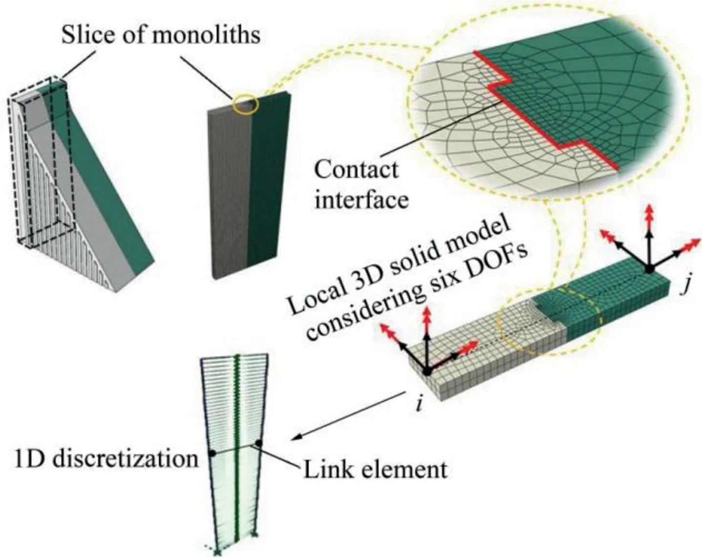
Fig.2.Stiffness assessment of link element using a local 3D FE solid model.
In this study,we used a local refined 3D FE solid model as an intermediate step to evaluate a 6×6 stiffness matrix of a representative link element for a given key geometry(Fig.2).The link element model was then inserted into a 3D beamcolumn model of a gravity dam(Fig.3(b)).The objective of this advanced grillage model was the local force demand evaluation in each key to identify critical keys and compute their corresponding DCRs.Fig.4 schematically represents an example of DCR assessment using a 2D representation in the Vy-Mzplane for an unfavourable case with negligible compressive force P.The dotted line represents the intersection of the multi-axial failure envelope in the Vy-Mzplane.Mcrand Vcrare respectively the key flexural and shear strength that can be estimated using the strength predictive equations of concrete design codes(Alcalde et al.,2013a,2013b;Curtis,2011).It is clear from Fig.4 that the classical procedure only considering the shear strength component(path(1)in Fig.4(a))results in an overestimation of the strength capacity of a shear key.In contrast,when the combined effects of shear and moment are considered(path(2)in Fig.4(a)),the DCR is estimated more precisely.For the case of path(2)in Fig.4(a),DCR is greater than 1.0,indicating a failure.

Fig.3.Three-dimensional model of concrete dam.
2.2.Formulation of stiffness matrix of a two-joint link element
Using the modelling from the previous section,a local refined 3D FE solid model with contact conditions was used to assess the stiffness of a two-joint link element(Fig.5).Contact forces acting on the male shear key are represented as arrows in Fig.5(c).
The stiffness coefficients were successively determined by imposing a displacement Djat the end node j of a male section and fixing the displacements of all other nodes and then by computing the reaction Riat the fixed end node i of a female section(Fig.5(b)).Considering the degree-of-freedoms(DOFs)at the end nodes i and j,the stiffness coefficient Kijwas determined as follows:

The stiffness matrix can therefore be computed by repeating the procedure for all DOFs,given in Eq.(2),where ux,uy,and uzare translational DOFs,and rx,ry,and rzare rotational DOFs available at the end nodes i and j.SYM means that the stiffness matrix is symmetric.
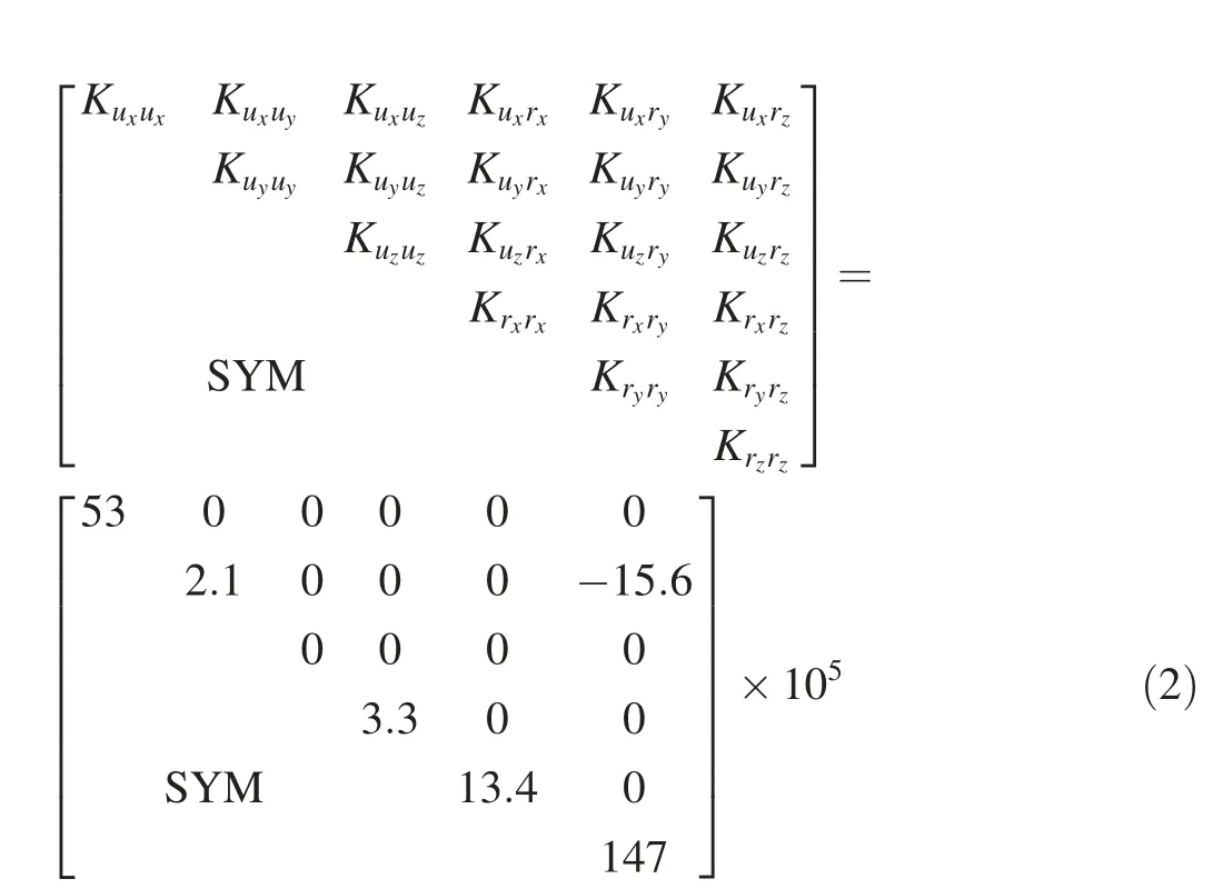
Six stiffness coefficients were found to be significant,including Kuxuxand Kuyuyin kN/m,Kuyrzin kN/rad,and Krxrx,Kryry,and Krzrzin kN·m/rad,in particular,Kuyrzrepresenting the coupling of upstream/downstream shear force Vyand torsional moment Mz.The stiffness matrix was computed for a link element of one-meter thickness.Therefore,link elements had to be positioned vertically at every meter in the beam model in Fig.5(a).
In Eq.(2),the unique nonzero off-diagonal term corresponds to the coupling shear/torsion term Kuyrz.This has a significant effect on the system response.Special attention must be paid to the sign of the coefficient that depends on local axis systems used in the structural analysis software(SAP2000 used herein)for the advanced grillage model(Fig.3(b)).
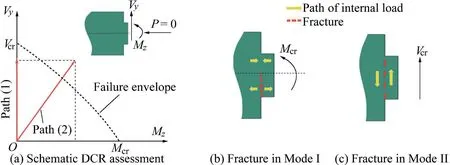
Fig.4.DCR assessment of single key.

Fig.5.Stiffness assessment of two-joint link element(units of size:m).
3.Consideration of multiple shear keys
3.1.Equivalent link element
The discussion in section 2 is applied here to a single key.In general,the number of keys,n,varies with the height of the monolith(Fig.1(a)).When only considering the shear stiffness along the y axis,Kuyuy,the intuitive choice for the equivalent stiffness of n keys would be nKuyuy.This parallel stiffness contribution is also applicable for the stiffness coefficients Kuxuxand Kryry.However,this is not the case for other coefficients in Eq.(2).
To consider the mechanical behaviour of multiple keys,refined 3D FE solid models are used with one to 17 keys.Fig.6 presents the geometry of some models and a typical mesh,with local refinement around the key for better assessment of contact forces.
In Fig.7,contact forces are shown for assessment of the torsional component Krzrz.A typical contact pattern can be observed regardless of the number of the keys.For the left-side portion(with respect to key centerlines),the normal forces are concentrated on the key vertical faces.Because of friction,these forces contribute to the shear force Vyalong the y axis.For the right-side portion,the normal contact forces are mainly concentrated on the horizontal faces.They contribute to the normal force component P along the x axis(Fig.7(a)).The pattern of tangential frictional contact forces(Fig.7(b))is consistent with the normal contact force pattern.For the leftside portion,the frictional forces act along the vertical faces of the keys and therefore contribute to loading of Mode I(Fig.4(b)).For the right-side portion,these forces act mainly on the key horizontal faces and therefore contribute to loading of Mode II(Fig.4(c)).
For a larger number of keys,the normal force component has been found to be predominant.The torsional component Krzrzis then proportional to the cubic number of keys.In the same way,typical contact patterns are found for other local models serving to assess the other stiffness coefficients.Figs.8-10 present the results of different FE simulations.They indicate the computed equivalent stiffness coefficients as a function of a given power of the key number n.In particular,Fig.10(a)verifies that the torsional stiffness is proportional to n3when n is larger than 7.
For a given key number n at each level of the monolith,it is possible to assess the six stiffness matrix coefficients(Eq.(2))of the equivalent link element to be used in the advanced grillage model(Fig.3(b)).
3.2.Assessment of internal force demand of a single key
Once the advanced grillage model is solved using a conventional software package,it is possible to compute the forces acting on each link element and displacements.For assessing the internal force demand of a single key,it is necessary to extract the forces sustained by one key.To obtain a rigorous solution to this problem,the initial local 3D FE solid model(Fig.6)for different numbers of keys can be used.The computed displacement from the grillage model should be imposed on the local model,in analogy to a substructure method.This approach can be implemented to compute the force component demand(Mfi,Vfi,and Nfi)of an individual key i with FEM,as shown in Fig.11.A second approximate and simple solution was developed in this study.Analytical relations were developed between the global forces acting on the link element and the local forces acting on the key,and the classical beam theory was adjusted to recognize typical contact patterns(e.g.,Fig.7).At this stage,the Mxcontribution was not considered,because preliminary results indicated that it is a reasonable assumption to divide Mx,computed in the link element,by the number of keys.

Fig.6.Consideration of multiple shear keys.
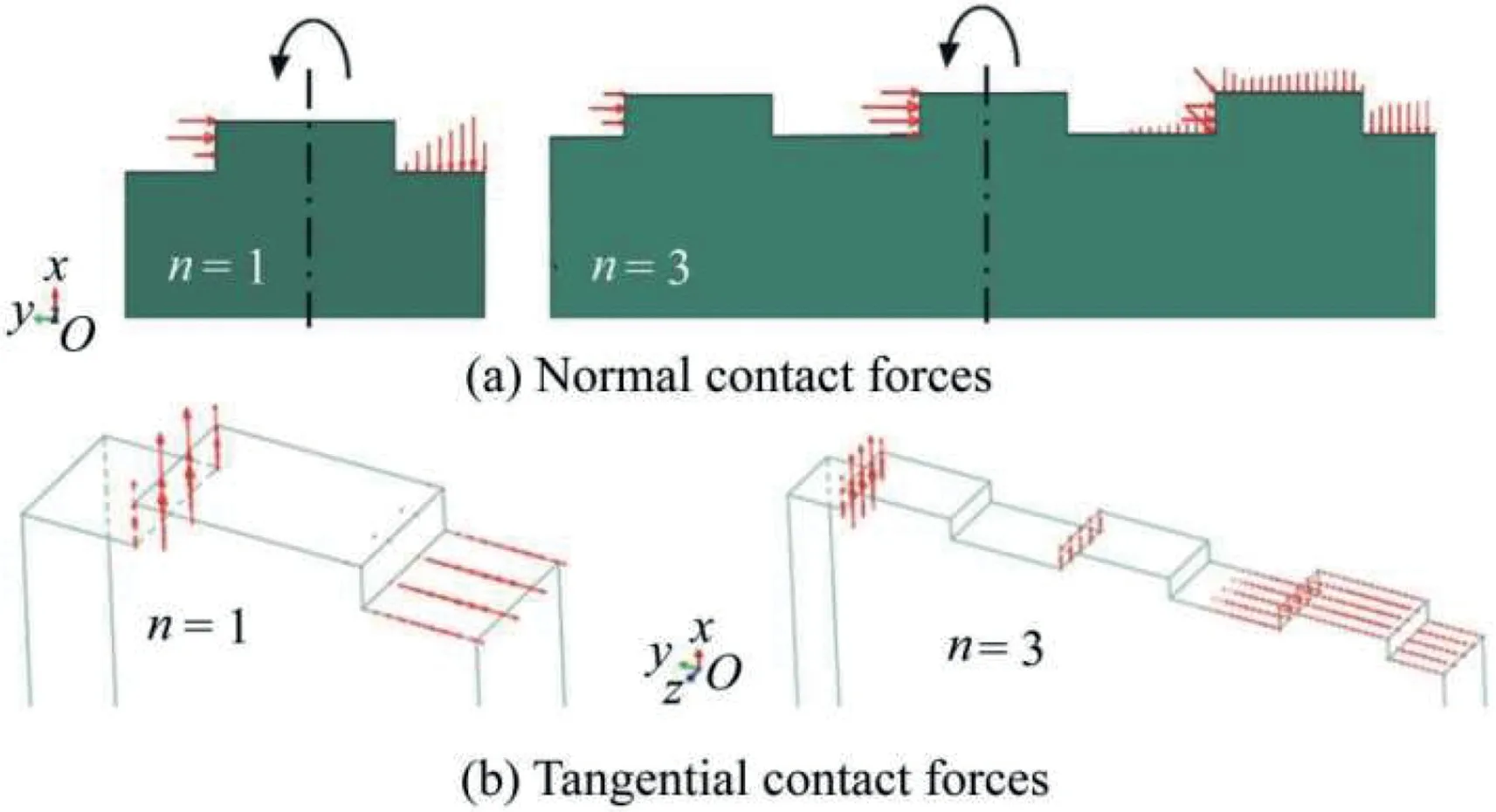
Fig.7.State of contact forces for assessment of coefficient Krzrz(only male section shown).
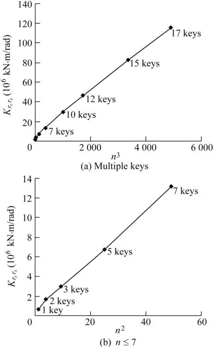
Fig.8.Assessment of bending stiffness coefficient Krxrx for multiple keys.
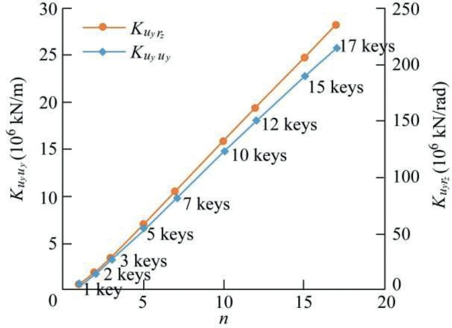
Fig.9.Assessment of shear and shear-torsional stiffness coefficients Kuyuy and Kuyrz for multiple keys.
The analytical solution was developed using classical beam theory for the case shown in Fig.11.The force components(Mf,Vf,and Nf)are applied to the link element,and the local components,Mfi,Vfi,and Nfi,have to be extracted for a single key i.They correspond to Mz,Vy,and P in Fig.1(b).
Two cases with low and high eccentricity,respectively,were studied.The low-eccentricity case is when Mf/Vf≤1.2L/2,where L is the length of the link element as shown in Fig.11.In this case,the formulae for local force components are the following:


The high-eccentricity case is when Mf/Vf>1.2L/2.In this case,Vfiis calculated with Eq.(3),and Nfiand Mfiare calculated as follows:
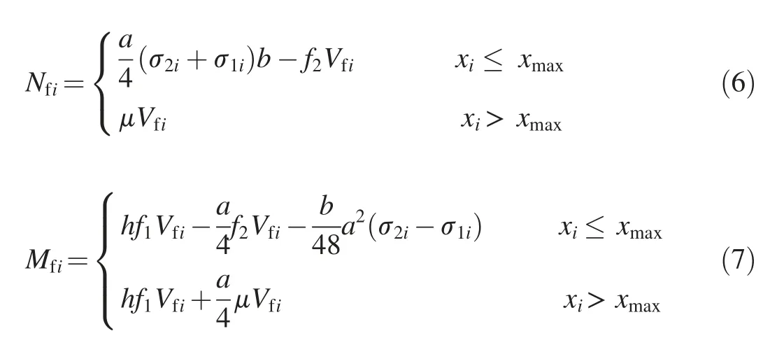
where a is the spacing between the keys,b is the thickness of the keys,μis the friction coefficient,and h is the height of the key.f0,f1,and f2are the shape factors depending on the local contact forces on each key and the key geometry,and the values were 0.1,0.5,and 0.2,respectively,for the geometry in this study(Fig.1(a)),obtained through the 3D FE solid models.σ1iandσ2iare the stresses acting on each key i(Fig.11),following a trapezoidal distribution.They are approximated by the following formulae:σ1i=σ(xi+a/4),andσ2i=σ(xi-a/4),whereσ=σmax(1-xi/xmax),with σmax=2Nf/(xmaxb)and xmaxbeing the length of the compressed ligament,given by the following formula:
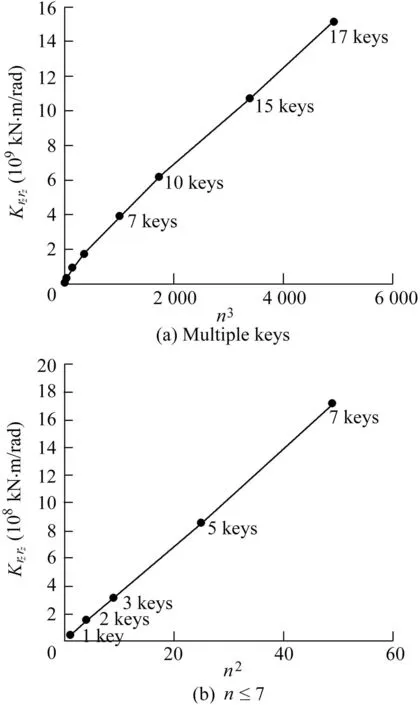
Fig.10.Assessment of torsional stiffness coefficient Krzrz for multiple keys.
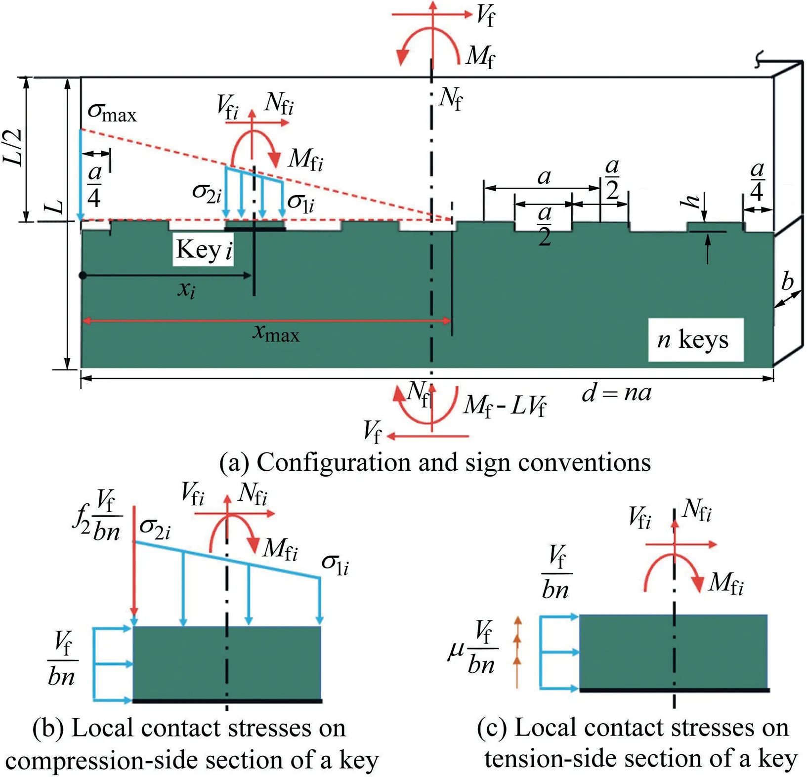
Fig.11.Force demand assessment of a single key.
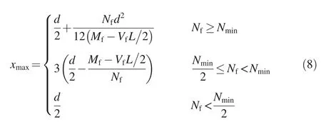
where Nminis the minimum axial compressive force required to have zero tension for given Mfand Vf,with Nmin=(6/d)(Mf-VfL/2);and d is the local depth of the monolith,with d=na.
Fig.12 shows an example for n=10,using 3D FE solid models and the analytical approximate solution(ANA)from Eqs.(3),(6)and(7).The example was selected to represent a high-eccentricity case because interesting conclusions can be drawn under frictional effects.The situations with friction(μ=1.0)and without friction(μ=0)are considered in Fig.13.Friction induces detrimental axial tensile forces,Nfi,in keys six to 10(Fig.13(b))in combination with increased moments,Mfi(Fig.13(c)).Tensile forces in combination with shear forces,Vfi,acting on a single key will trigger premature failure as compared to the case,in which no tensile force is developed(μ=0 in Fig.13(b)).
Other 2D plane configurations have been considered through simultaneous combinations of rz,ux,and uyin the upper model portion in Fig.12.The predictions of the analytical solution were in general satisfactory as compared to the reference FE solution.Fig.13 shows the importance of considering the multi-axial behaviour of shear keys and the frictional effects,especially for high-eccentricity cases.In these cases,the classical approach,considering only the shear stiffness coefficient,Kuyuy,of the keys tends to underestimate the internal force demand of the shear keys located on the uncompressed side of the section(Fig.13(b)).The tensile forces acting on the uncompressed side are not considered in the classical approach,though they have a critical effect on the strength of the keys.
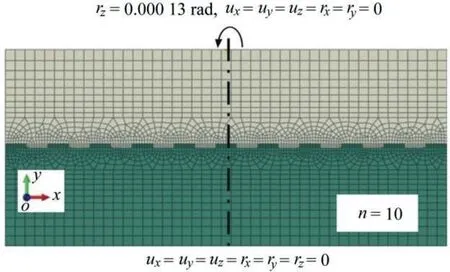
Fig.12.Geometry and boundary conditions for example with 10 keys.

Fig.13.Force demand assessment in a single key with and without friction(FEM is the reference solution,and ANA is the analytical solution).
4.Validation examples:one-key vs.seven-key rectangular models
Two different uniform rectangular monolith validation examples,one with a single key(Fig.14(a))and the other with seven keys(Fig.14(b)),were considered in this study.The elastic modulus,Ec,was equal to 25 GPa and the Poisson's ratioνwas equal to 0.2.The results from the advanced grillage model(beam model using SAP2000)were compared to those from the 3D FE solid model using ABAQUS(Hibbitt et al.,2014),and are considered herein as reference solutions.

Fig.14.Application examples(units of size:m).
A triangular-shaped load pattern with a 150 kPa pressure at the top was applied to the female section of each model(cream-coloured in Fig.(14)).The transferred forces were then evaluated at different elevations,z,on the male section(greencoloured).For both the beam and solid models,fixed conditions were applied at the base of the two sections.For the 3D FE solid model,the transfer of forces was through contacts between keys(μ=1.0).For the beam model,force transfer was made using the link element a-b,whose stiffness matrices were assessed using the procedure developed in this study.
The computed results are shown in Fig.15,in terms of transferred shear forces Vy,torsional moment Mz,and bending moment Mxin the green-coloured monolith of each model.

Fig.15.Comparisons of transferred shear force,torsional moment,and bending moment obtained from 3D FE solid model(Solid)and advanced grillage method(Beam).
Generally,strong agreement was found between the results of the advanced grillage method and the 3D FE solid model.Exceptions are the transferred torsional moment(Mz)near the base where stress concentrations and variations due to the fixed boundary conditions were different in the models.It was verified that Poisson's ratio has no significant effect at this level.When Poisson's ratio was set to zero in the FE models,the differences in FE internal forces were then limited to the order of 5%.Observational and experimental evidences of seismic behaviour of the gravity dam have shown that a crack in the upper zone of the dam is expected.The advanced grillage method is thus particularly suitable to computing the DCR of shear keys,potentially restraining crest block seismic sliding displacements.
5.Application to a dam model
5.1.Synthesis of proposed method
To apply the proposed advanced grillage method to a dam,with the objective of computing the shear key DCR,the steps should be followed:
(1)Develop 3D FE solid models considering the specific key geometry for one,three,five,and the largest number of keys,nmax,for the dam.
(2)Compute the six nonzero link element stiffness coefficients in Eq.(2)for n=1,3,5,and nmax.Use interpolation to compute link element stiffness coefficients if n is different from the above selected values,recognizing that Kuxux∞n; Kuyuy∞n;Krxrx∞n2for n≤7,and Krxrx∞n3for n>7;Kryry∞n;Krzrz∞n2for n≤7,and Krzrz∞n3for n>7;and Kuyrz∞n.
(3)Develop the advanced grillage model for the dam and assign proper stiffness coefficients to link elements.
(4)Perform the grillage analysis and extract link element displacements and loads.
(5)Impose computed link element displacements(or loads)to the corresponding FE solid models developed in step(1)to compute the force demand of individual keys.Alternatively,simplified analytical formulae could be developed as outlined in section 3.
(6)Estimate key strengths of Vcrand Mcr(Fig.4)and compute the DCR.At this stage a linear failure envelope(Vy/Vcr+Mz/Mcr=1)could be conservatively used.
5.2.Application to dam model with two monoliths
The procedure described above was applied to the two dam monoliths with a variable number of keys along the height as shown in Fig.14(c).A 150 kPa pressure was applied following an inverted triangular pattern.Results are shown in Fig.16.The classical approach that considers only the shear component(Beam_shear_K in Fig.16)was compared to the multiaxial stiffness approach(the advanced grillage method)used in this study(Beam_multi_K in Fig.16).
Fig.16 shows that the resulting link element forces agree with those from the 3D FE solid model,with some differences near the base of the structure,as in the validation examples.Also,consideration of shear key multi-axial stiffness results in a better assessment of the transferred shear force and bending moment.The classical approach is shown to significantly underestimate the intermonolith transferred shear forces from the base to the elevation of 50 m as compared to the results of the grillage method and 3D FE solid model.Transferred torsional moments are not available using the classical approach.This is a severe limitation of the classical method,which is significantly improved by the proposed grillage method.These results clearly show the advantage of the advanced grillage method,in comparison to the classical approach applied in practise.
To compute the DCR,the internal forces of individual shear keys,Mfi,Vfi,and Nfi,should be computed as described in section 3.In the absence of normal compressive forces,the shear strength Vcrcould be estimated according to Vcr=Ac,where A is the sheared area,with A=hb(Fig.11),and c is the cohesion(Curtis,2011).The flexural strength Mcrcould be estimated from the beam theory,with the protruding key section considered to be a cantilever,and Mcr=ftbh2/6,where ftis the tensile strength of concrete.

Fig.16.Comparisons of transferred shear force,torsional moment,and bending moment obtained from classical approach only considering shear stiffness,multi-axial stiffness approach,and FE solid model.
The application of the proposed method to the system of two monoliths is simplified for illustrative purposes.We are currently conducting complementary work(1)to apply the advanced grillage analysis in a seismic assessment of a complete dam(Fig.3(a))using no-tension link elements,and(2)to perform Vcrand Mcrassessment using a non-linear smeared crack constitutive law in local FE solid models of shear keys within the framework of ABAQUS and previous fracture mechanics experiments(Kaneko et al.,1993a,1993b).
6.Conclusions
This study examined a novel and computationally efficient 3D advanced grillage method for the assessment of local DCR of shear keys.The main conclusions can be summarised as
(1)Generally,strong agreement is found between the results of the proposed 3D advanced grillage model and the 3D FE solid model,particularly in the upper region of the dam.Exceptions are the intermonolith transferred shear forces(Vy)and torsional moments(Mz)near the base.
(2)The classical approach,using only the 1D shear stiffness,is not sufficient to obtain all the internal forces imposed on the keys.The six stiffness coefficients in Eq.(2)have been found significant in quantifying the forces required to calculate the shear key DCR.
(3)The classical approach,considering only shear transfer across monoliths,significantly underestimates the shear force demand acting on shear keys as compared to the proposed advanced grillage method and 3D FEM analyses.
(4)The assessment of the moment Mzacting on a single key is important for a proper DCR evaluation(Fig.4).This moment contributes to the fracture in Mode I,which is believed to be significant for the case of a plain concrete key.
(5)Concrete-concrete friction on the vertical key face has been found to induce detrimental tensile forces on individual keys when a moment(or rotation),Mz,is applied to a contraction joint with several keys,leading to an important finding of the study,i.e.,consideration of the tensile and shear forces on a key in the advanced grillage method will most likely result in a premature failure,as compared to the classical approach,in which only shear forces are considered.
(6)In the current version,the advanced grillage method applies the resulting displacements to a local 3D FE solid model of the joint with keys.As shown in section 3,it is also possible to develop an analytical formulation to extract the local force demand of a shear key using strength of material,while considering the contact conditions for different load combinations.
Declaration of competing interest
The authors declare no conflicts of interest.
 Water Science and Engineering2020年3期
- Water Science and Engineering的其它文章
- Impacts of topographic factors on regional snow cover characteristics
- Evaluation of alum-based water treatment residuals used to adsorb reactive phosphorus
- Phosphorus removal by adsorbent based on poly-aluminum chloride sludge
- Characterization of cobalt ferrite-supported activated carbon for removal of chromium and lead ions from tannery wastewater via adsorption equilibrium
- Acclimatization of microalgae Arthrospira platensis for treatment of heavy metals in Yamuna River
- Influences of flow rate and baffle spacing on hydraulic characteristics of a novel baffle dropshaft
